Subaru Front Control Arm Front Inner Bushing
- Brandyn Mowat

CB-4425K Standard Bushing
CB-4428K Offset Bushing
Front Control Arm Inner Bushing
Subaru STI 2011-2021
Subaru WRX 2015-2021
Congratulations on your purchase of the COBB Tuning Roll Center Correction Kit! The following instructions will assist you through the installation process. Please read them BEFORE beginning the install to familiarize yourself with the steps and tools needed. If you feel you cannot properly perform this installation, we HIGHLY recommend you take the vehicle to a qualified and experienced automotive technician.
Table of Contents
While You're There
While doing this installation it's an easy time to do other installations such as sway bars and endlinks. Maintenance items such as the Balljoints that can be on their way out, or potentially damaged while removing the stock arms are a good idea to have on hand, or replace at the same time as they make the whole procedure easier.
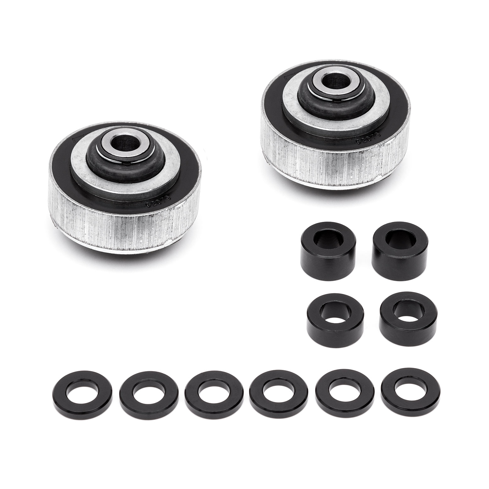
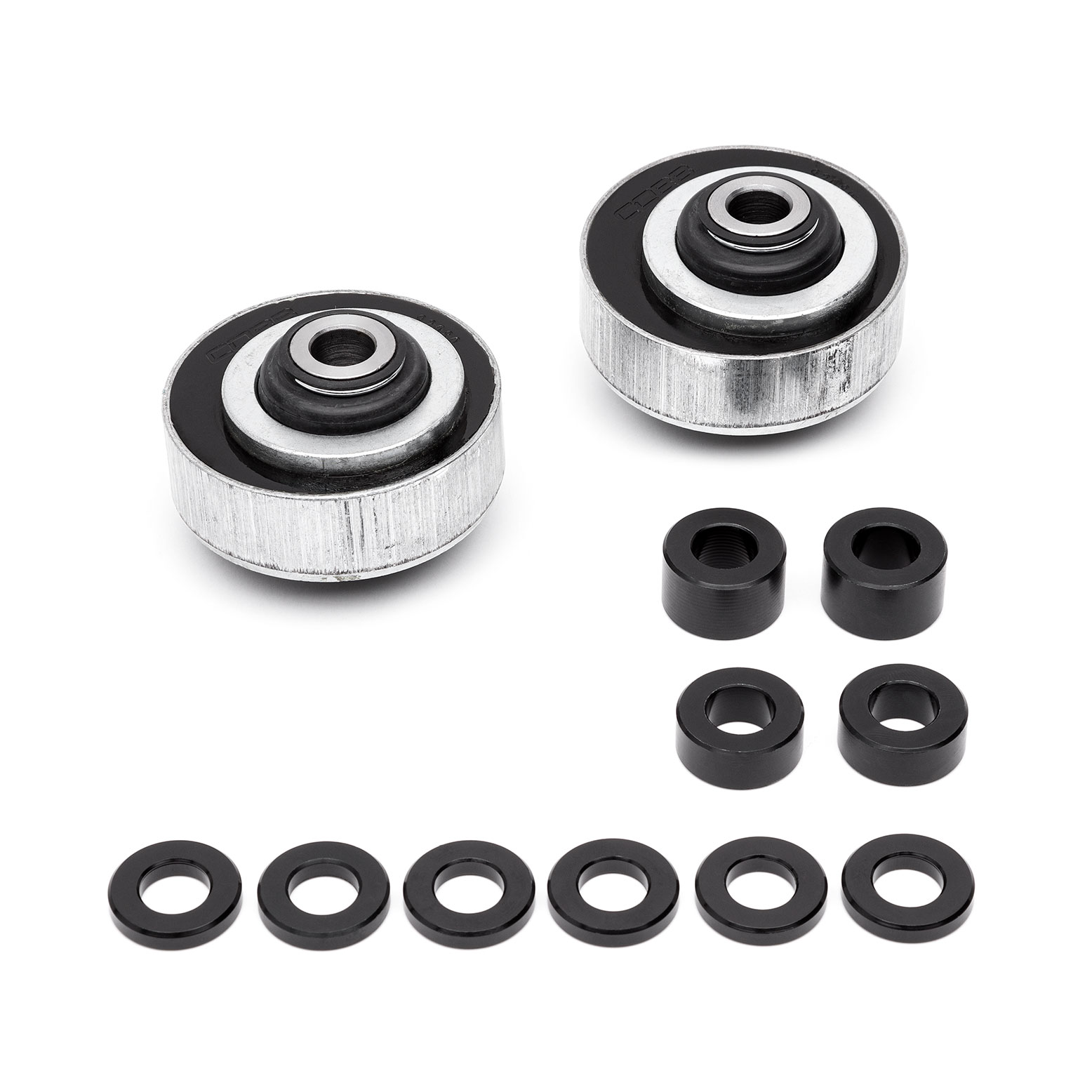
Parts List
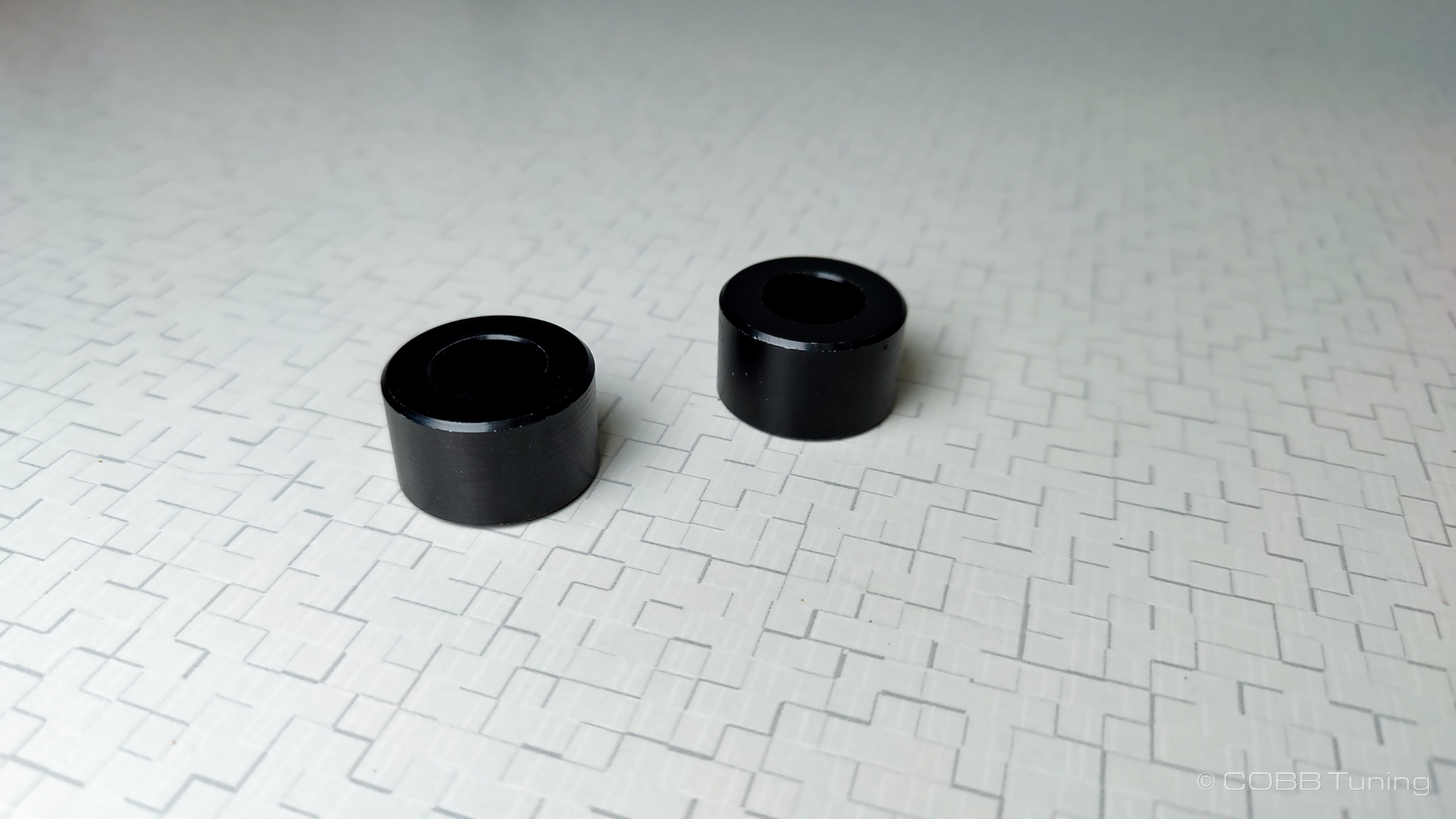
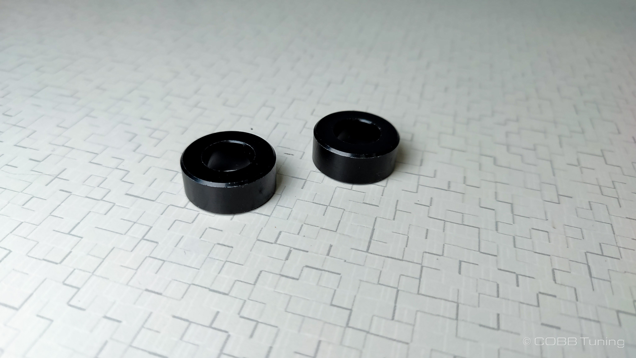
Offset Bushing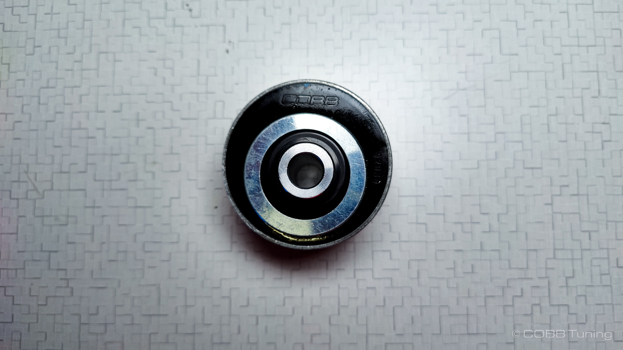
Standard Bushing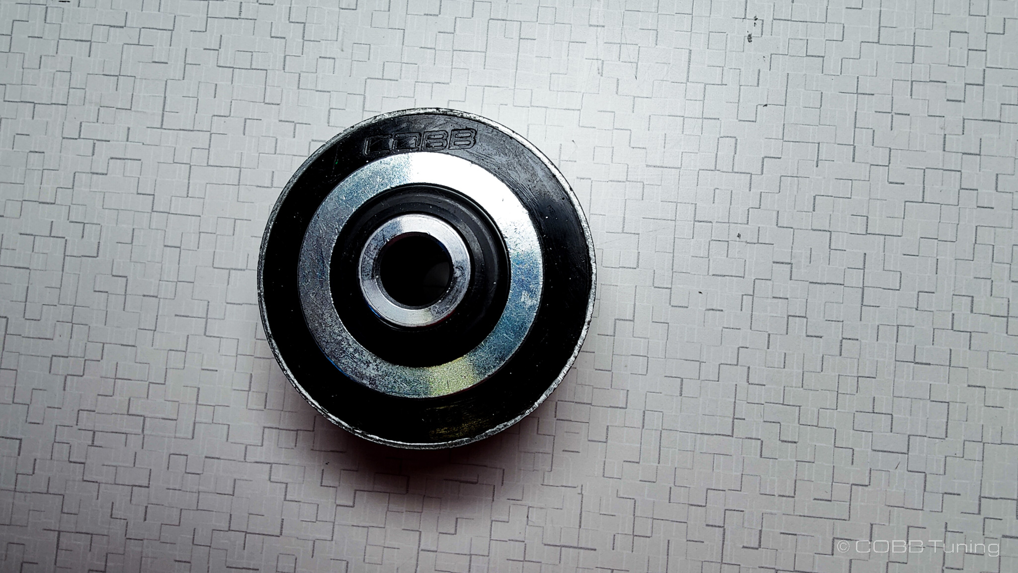
Tools Needed
Sockets
1/2"
- 1/2" ratchet
- 1/2" 6" extension
- 1/2" 14mm socket
- 1/2" 19mm socket
Hand Tools
- Needlenose pliers
Wrenches
- 14mm combination wrench
- 17mm combination wrench
- 19mm combination wrench
Stock Control Arm Removal
Many of these components are a common spot to collect rust, so going through and hitting them with a penetrating oil the night before you plan to do the work can make things much easier when it comes time.
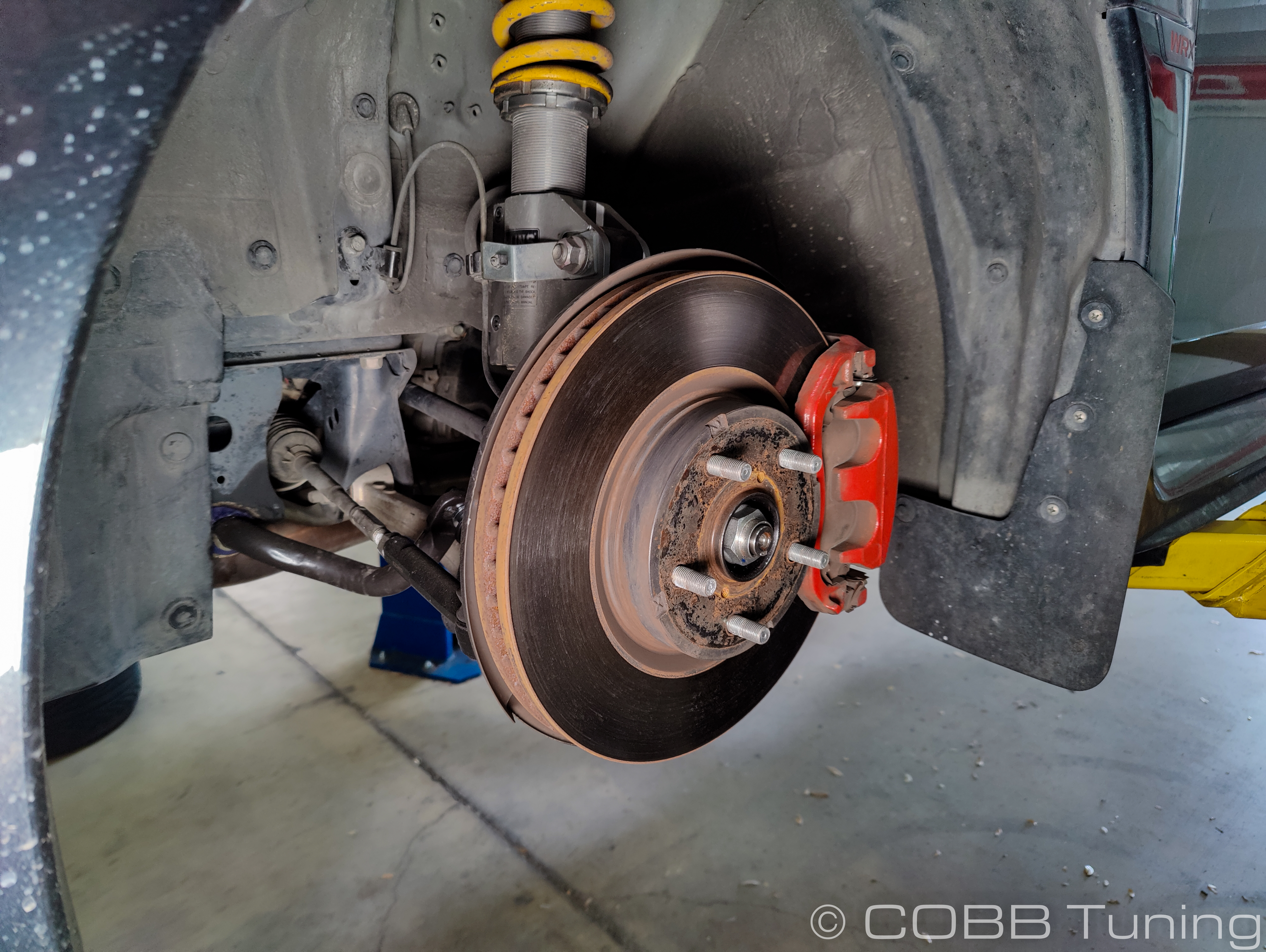
- Park your car in a flat, level area and allow it to cool down properly.
- Jack your car up and support it properly, either using a lift, ramps, or jack and jack stands.
- Lay a blanket or cardboard down under the car, or grab a creeper. In this case his name is Andrew
- Remove the front wheels of the car to get easy access to the areas we'll be working on.
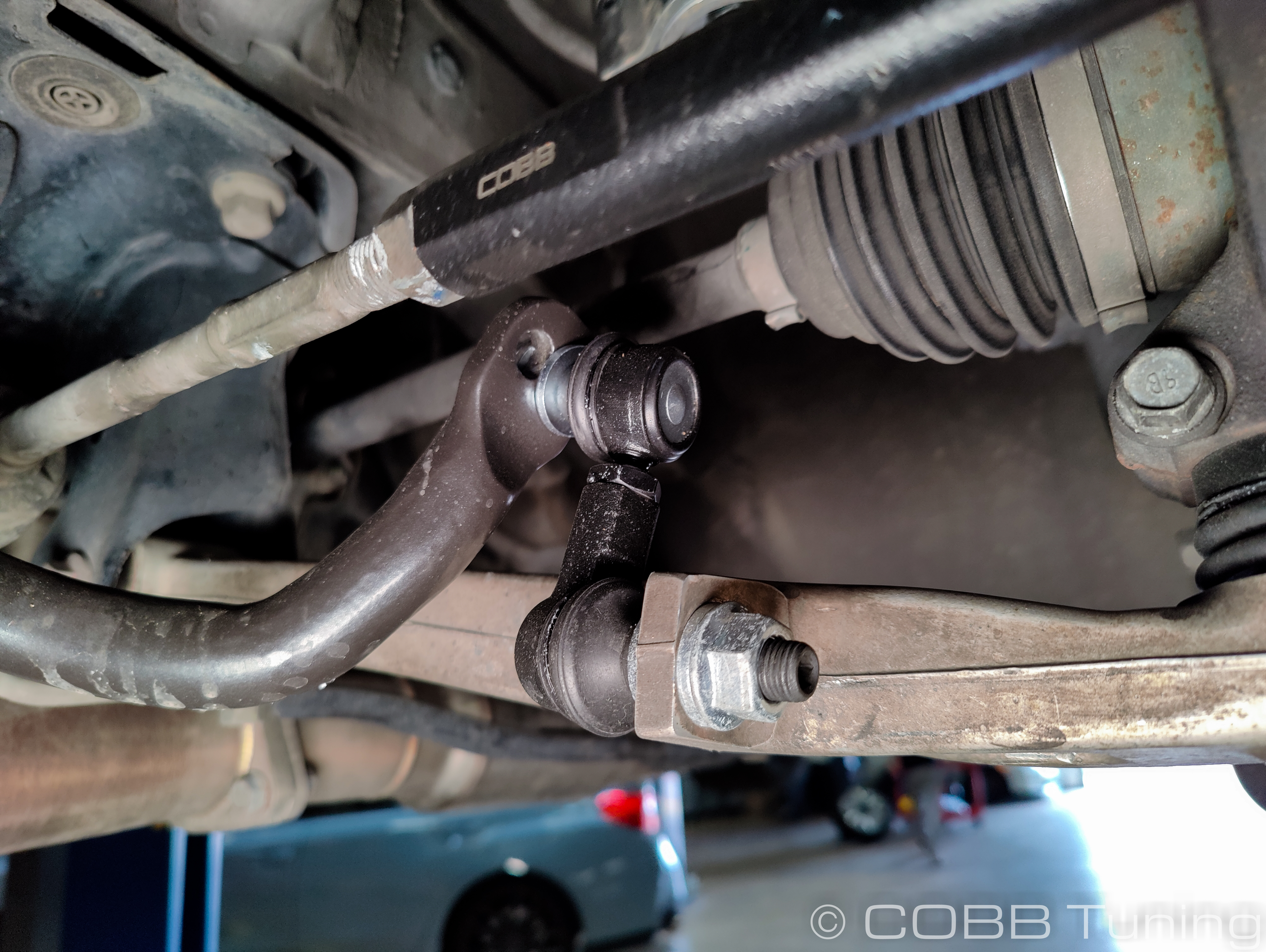
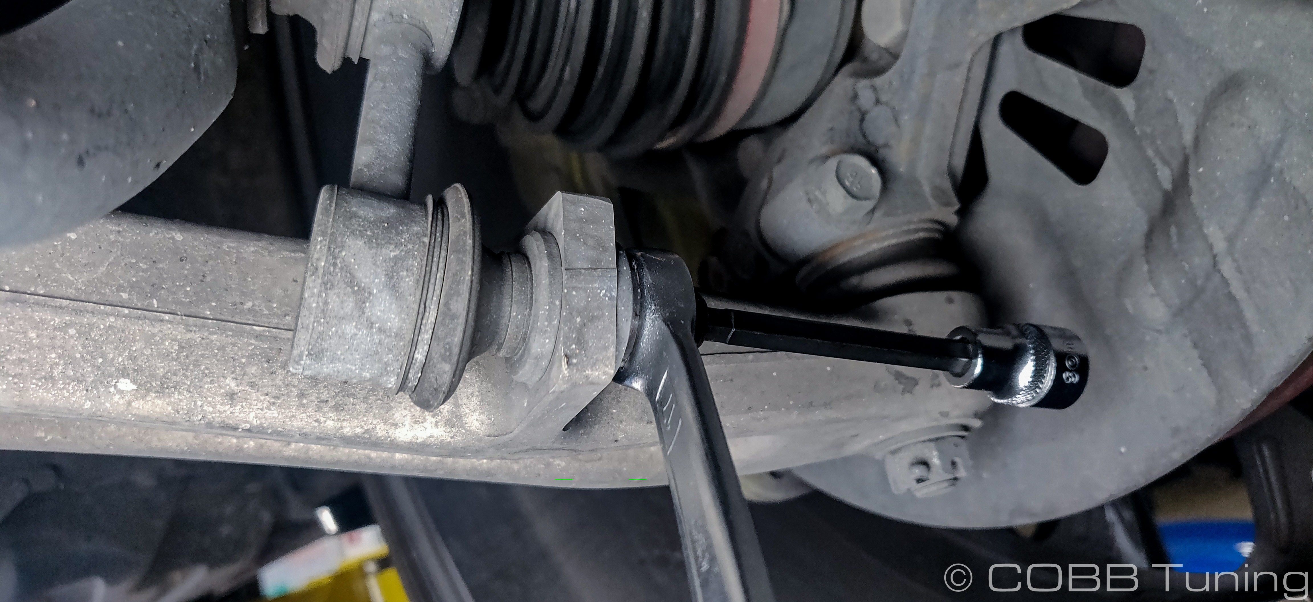
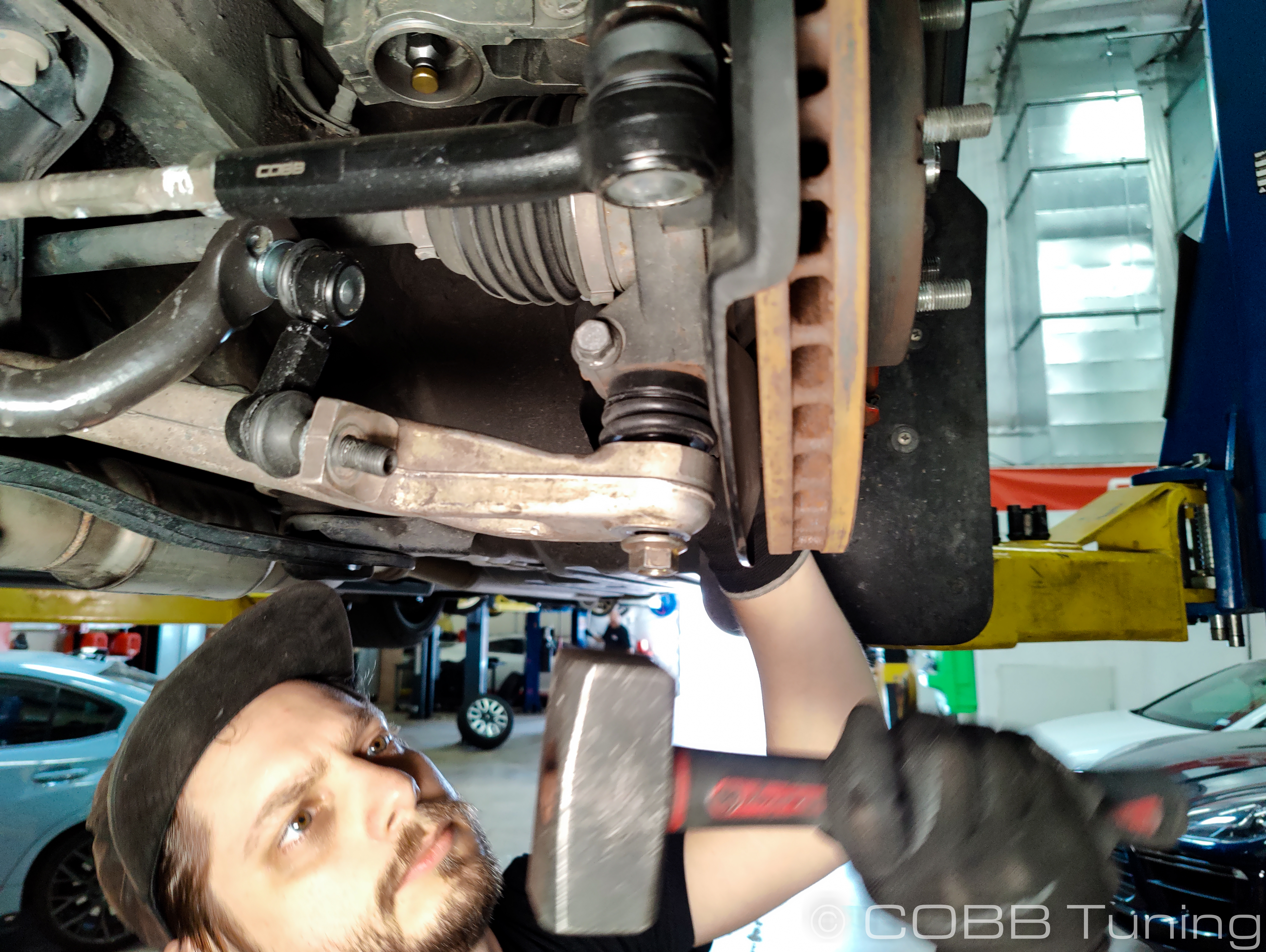
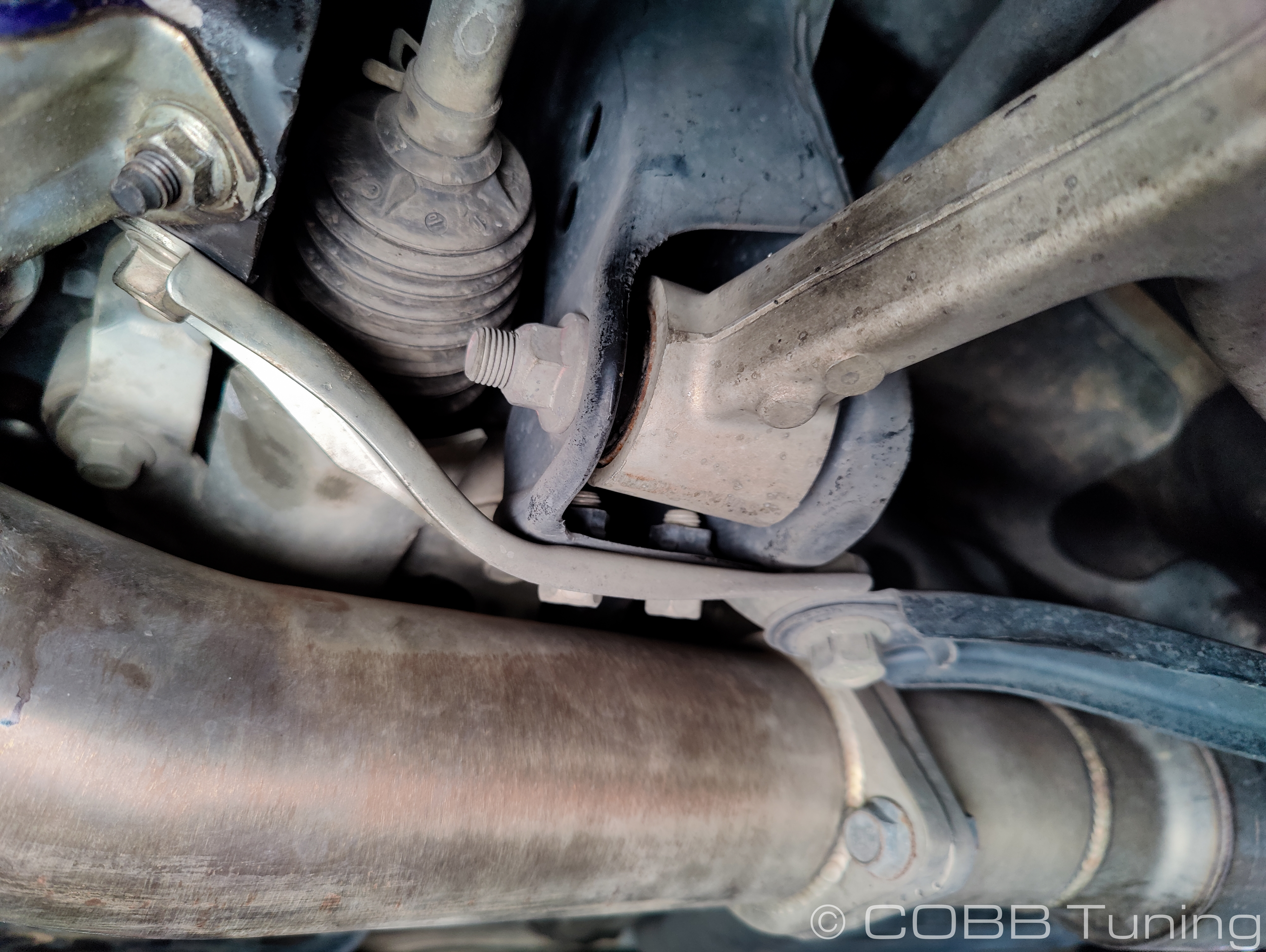
- Moving to the front end link where it meets the control arm, use a 17mm wrench to undo the nut while using a m6 allen wrench to hold the center of the endlink and keep it from spinning. Break each side loose first (sway bar and control arm) and then remove the nut completely. Repeat with the other side.
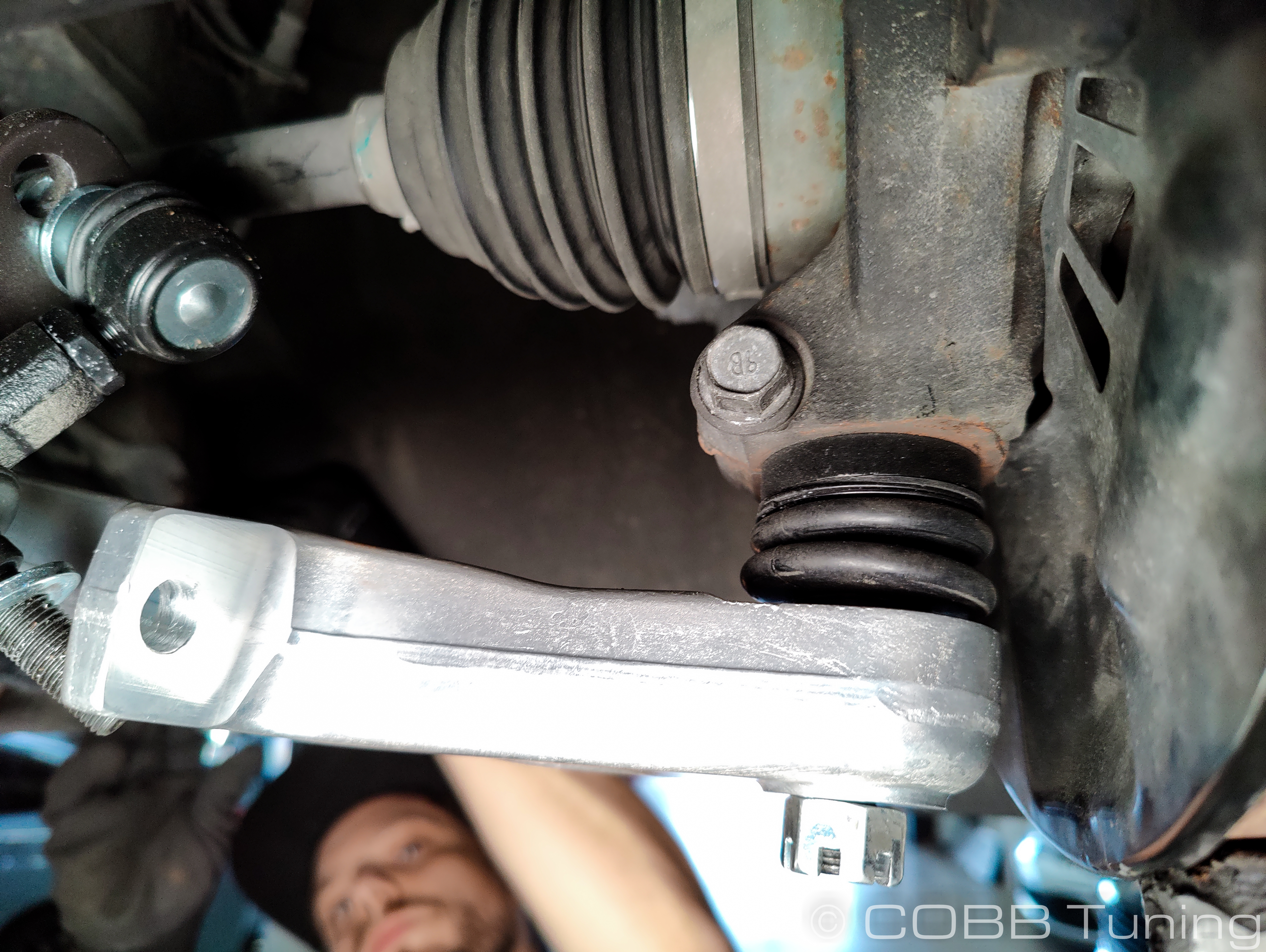
- On the bottom of the spindle straighten the cotter pin and remove it from the ball joint/castle nut.
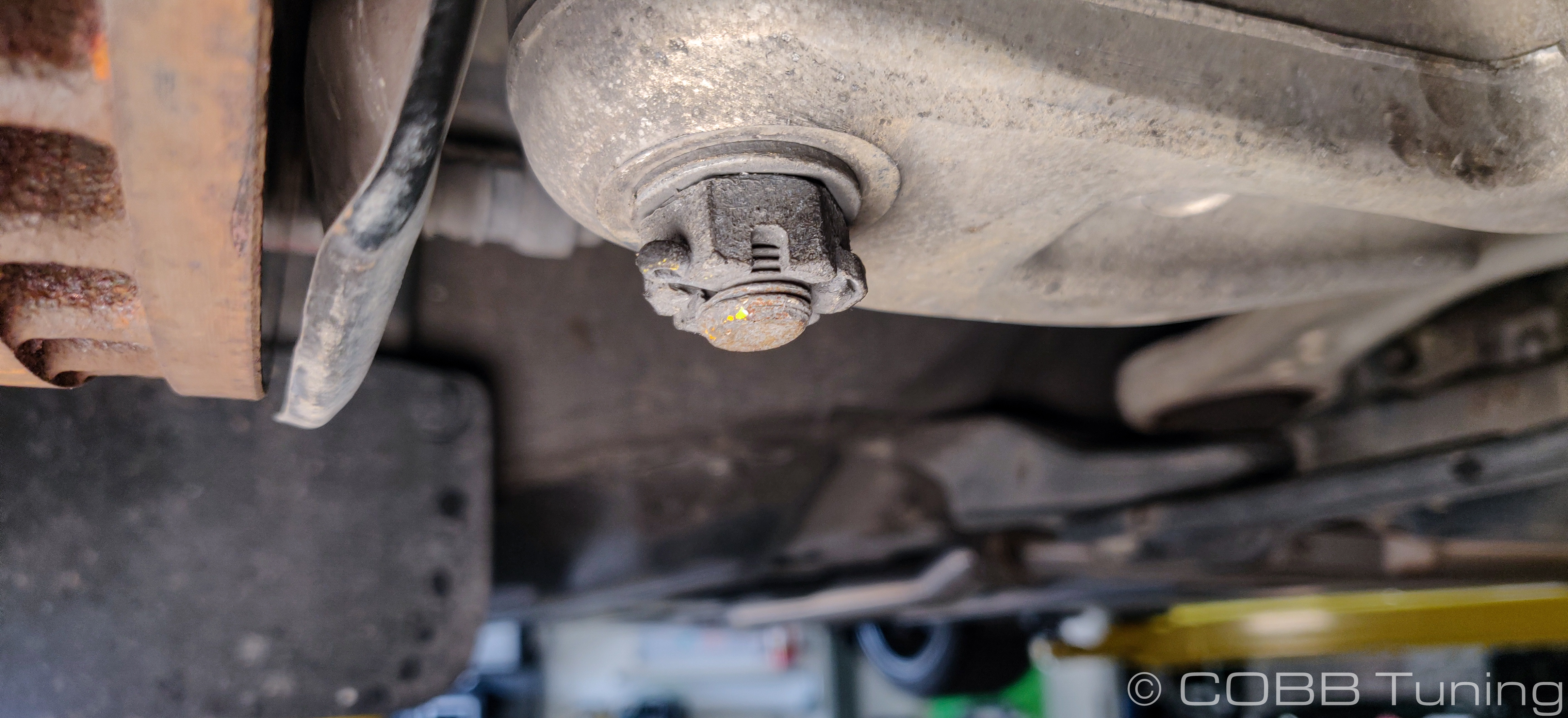
- Break the nut loose using a 19mm socket but leave it installed loosely for now.
- With the nut still holding it inplace on the bottom gently tap downwards on the control arm to remove the ball joint from the spindle control arm. In some cases if it's fairly rusty (ours was). Eventually it should come free. Now is a good time to clean out any rust in this area and coat it with a thin layer of lithium grease or similar to prevent rust in the future. If it isn't coming free, tap gently upwards on the nut to push the balljoint up.
- Undo the 3 19mm bolts and single 17mm bolt holding the rear control arm support bracket in place.
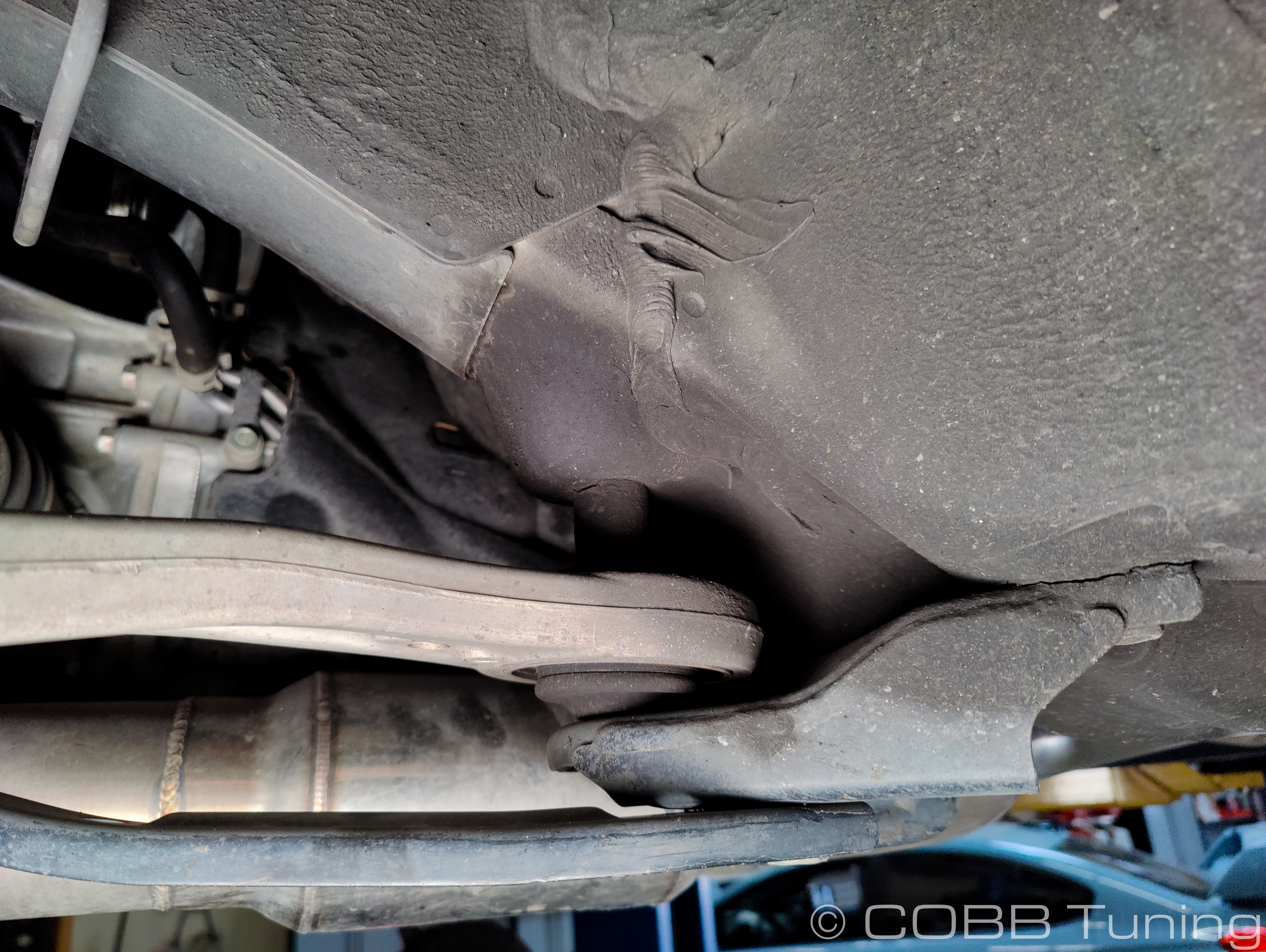
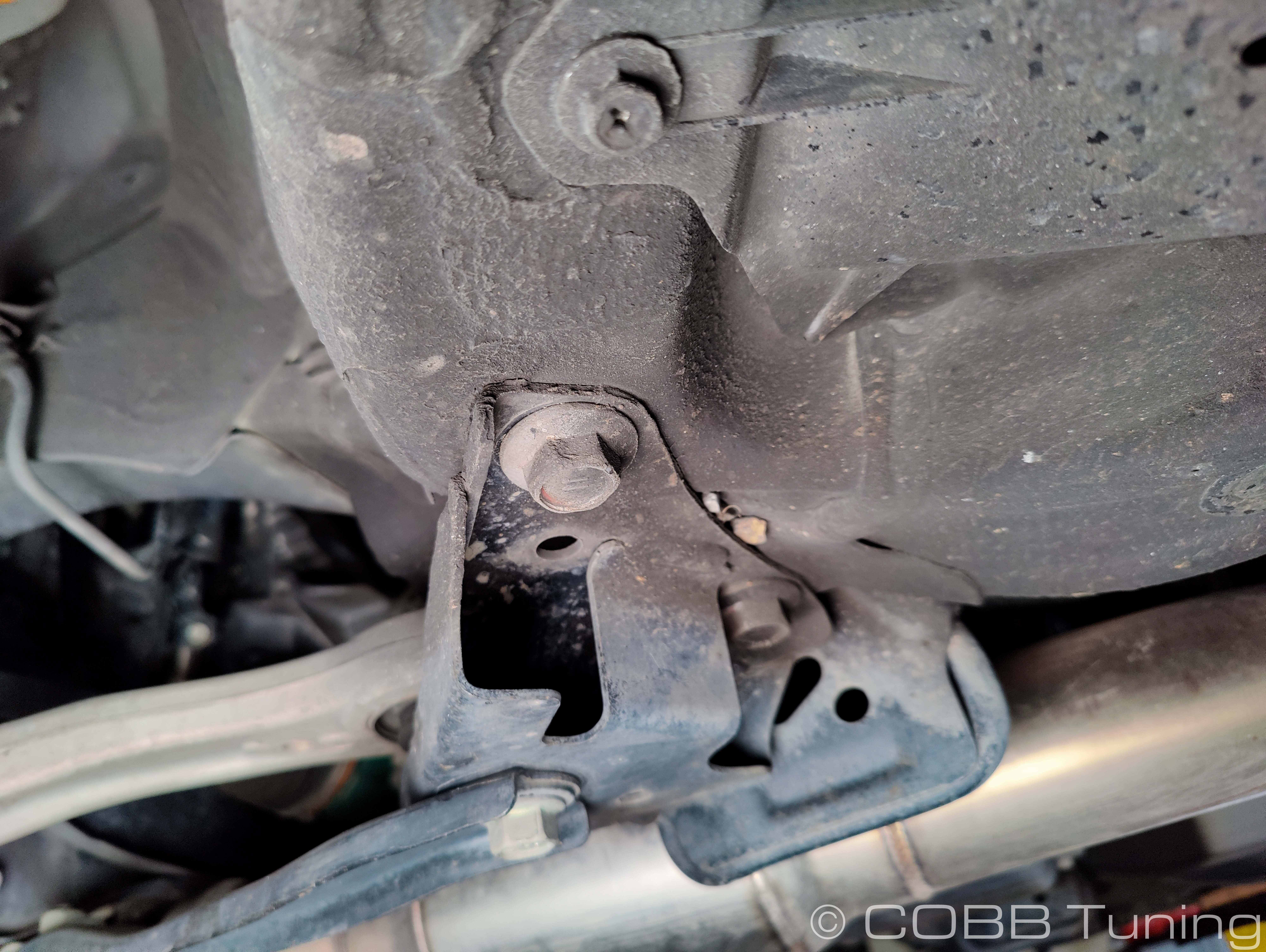
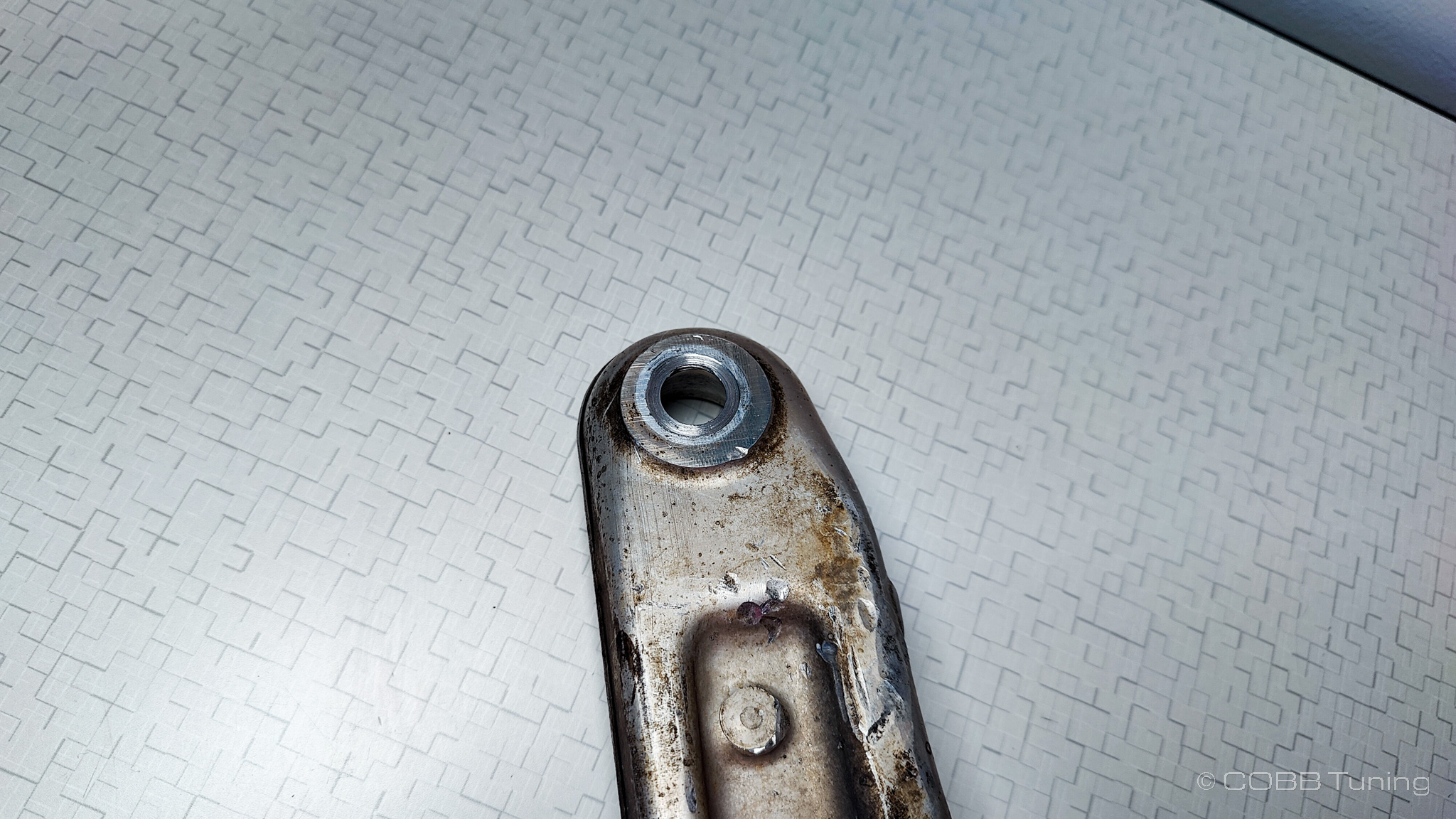
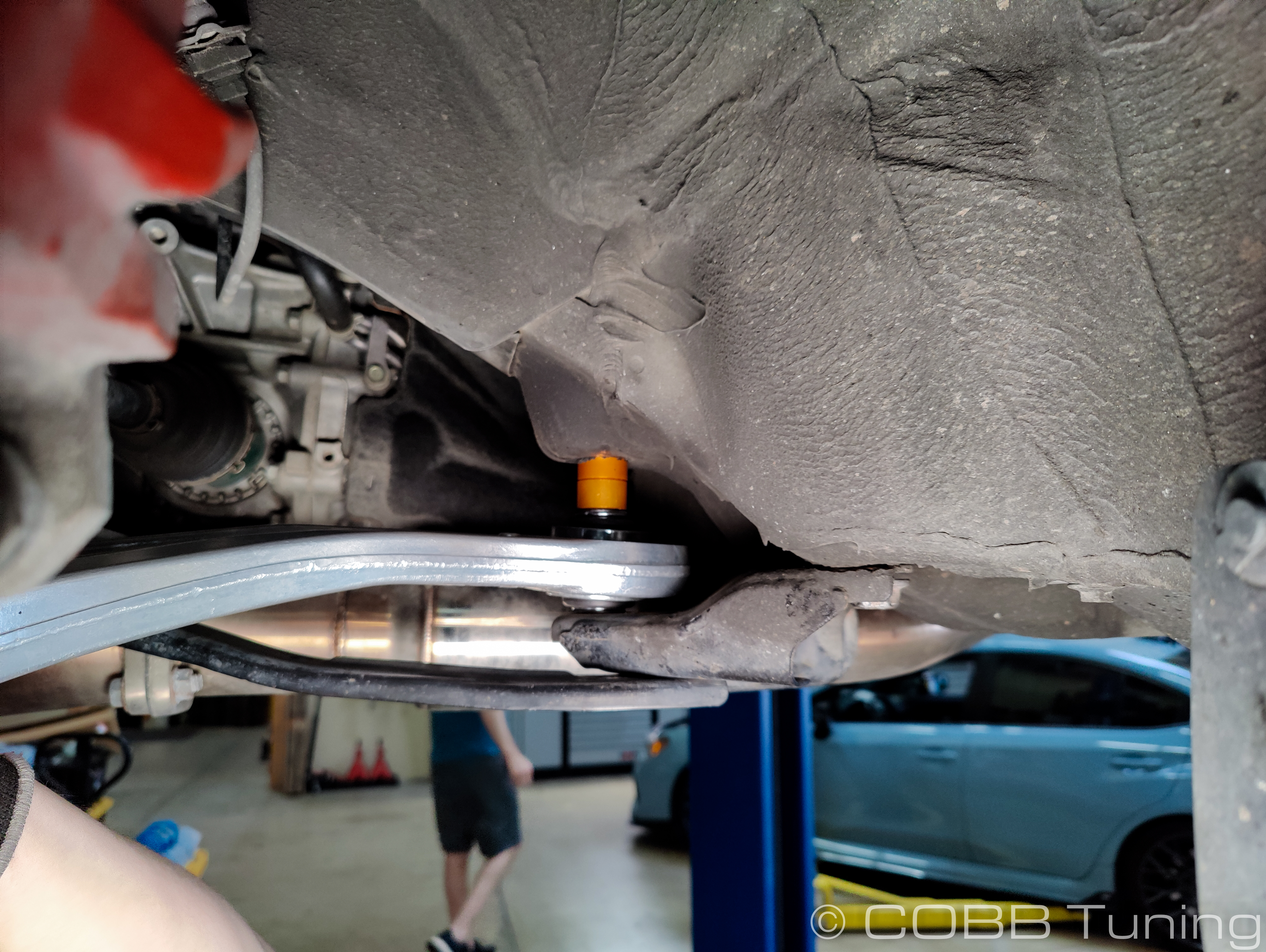
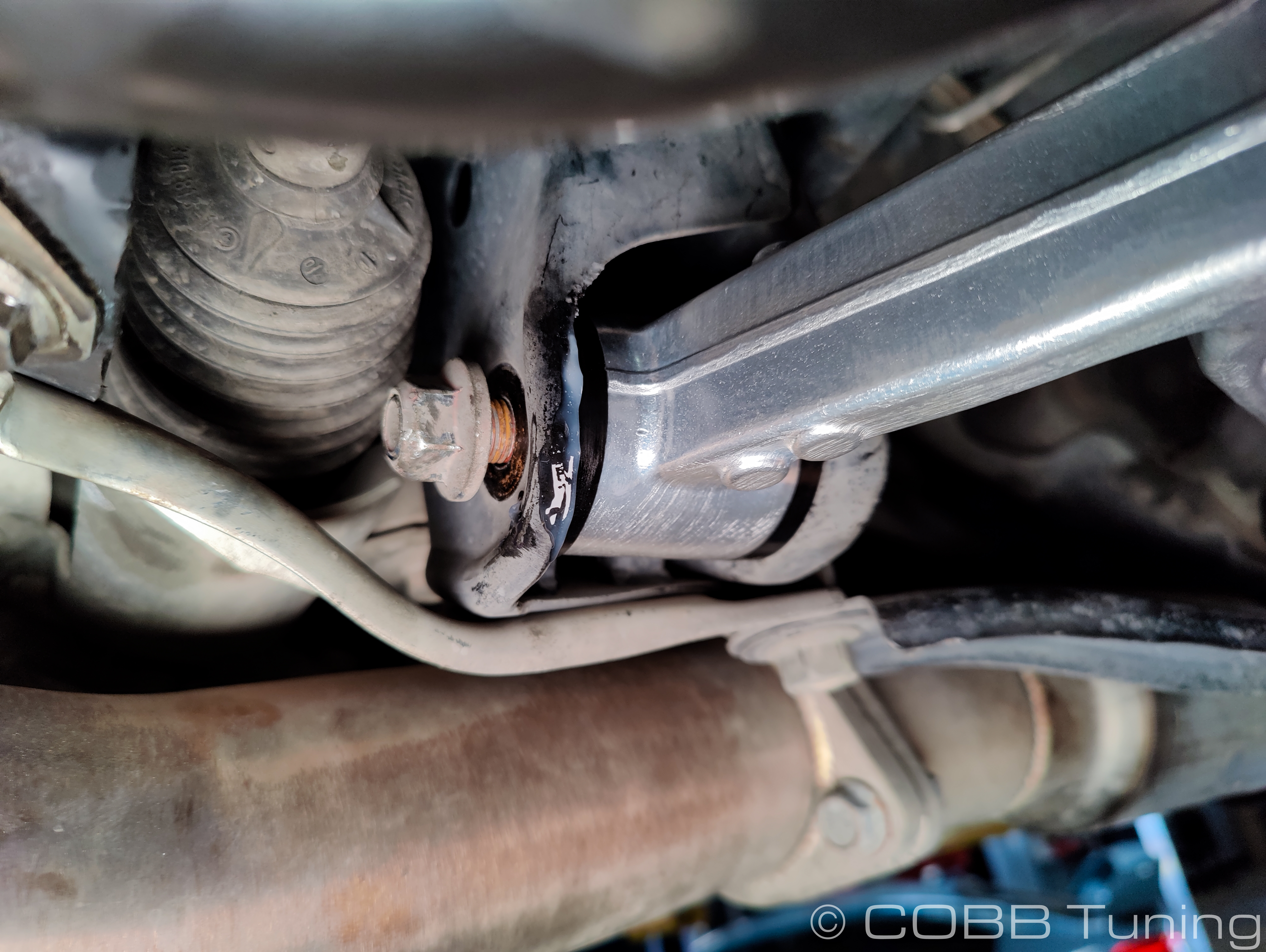
- Remove the nut and bolt holding the front control arm bushing to the chassis using your 17mm socket and wrench.
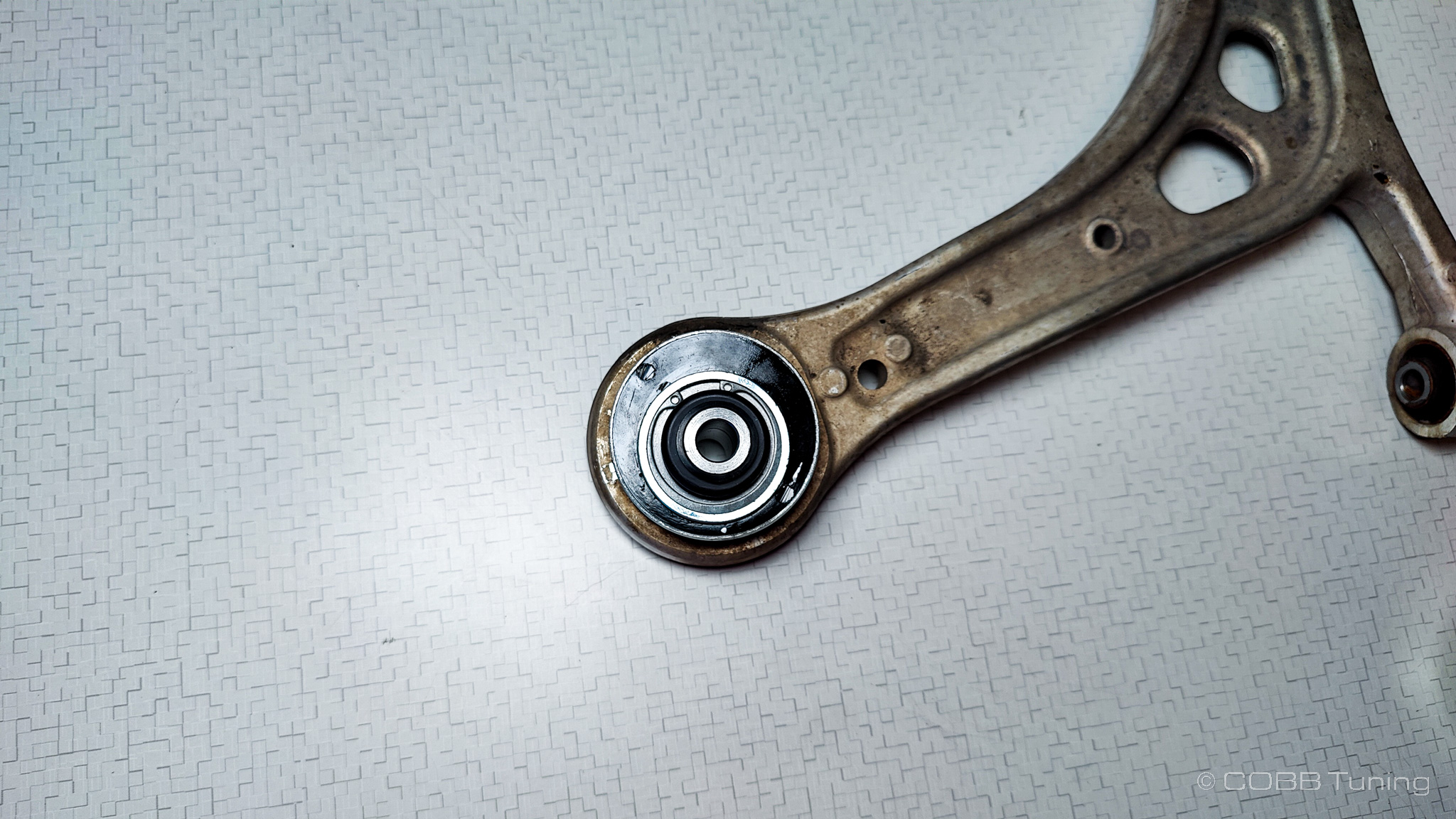
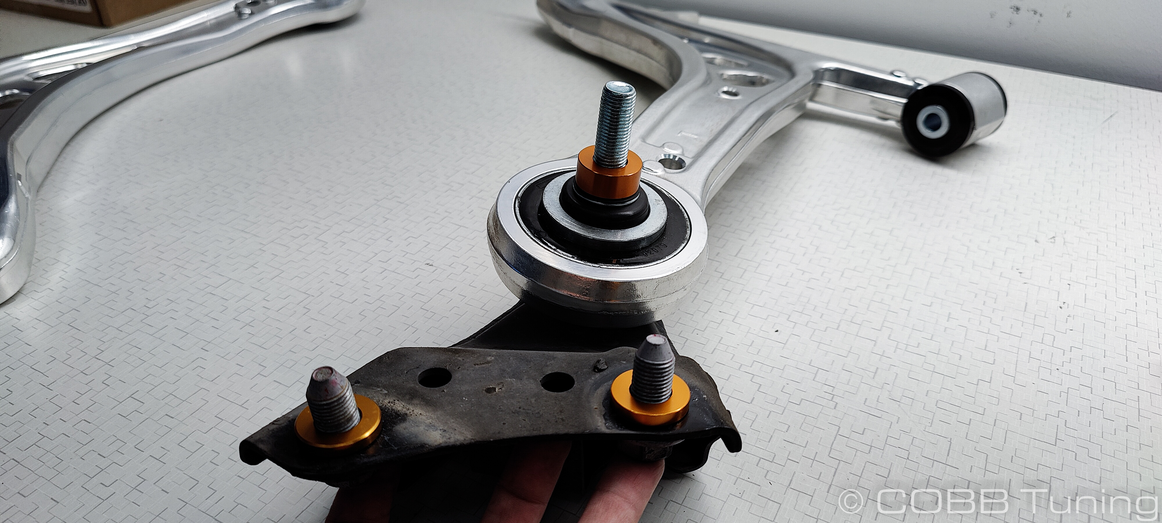
- You should be left with a bare control arm. This end is the bushing we're targeting.
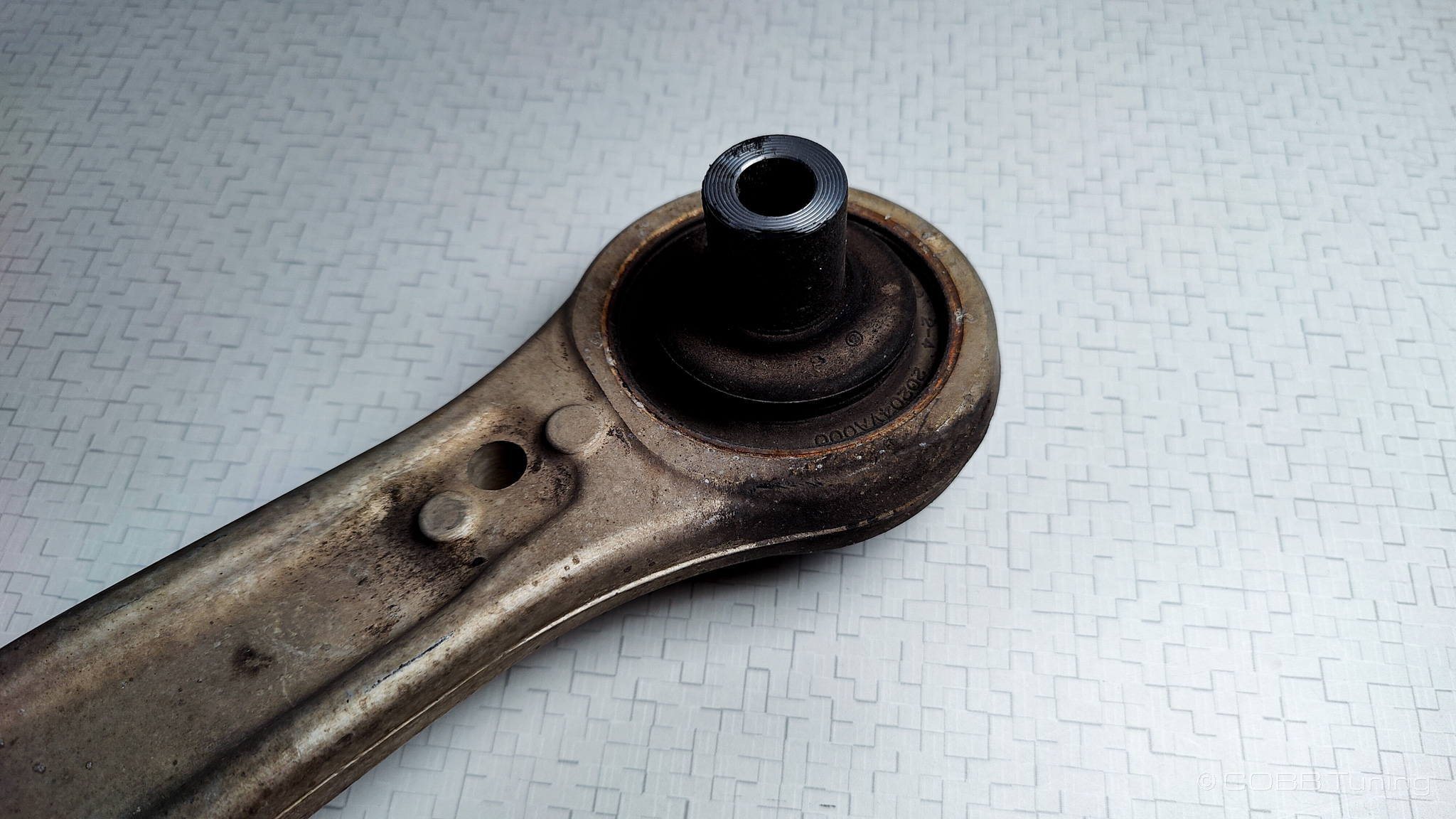
Bushing Removal and Installation
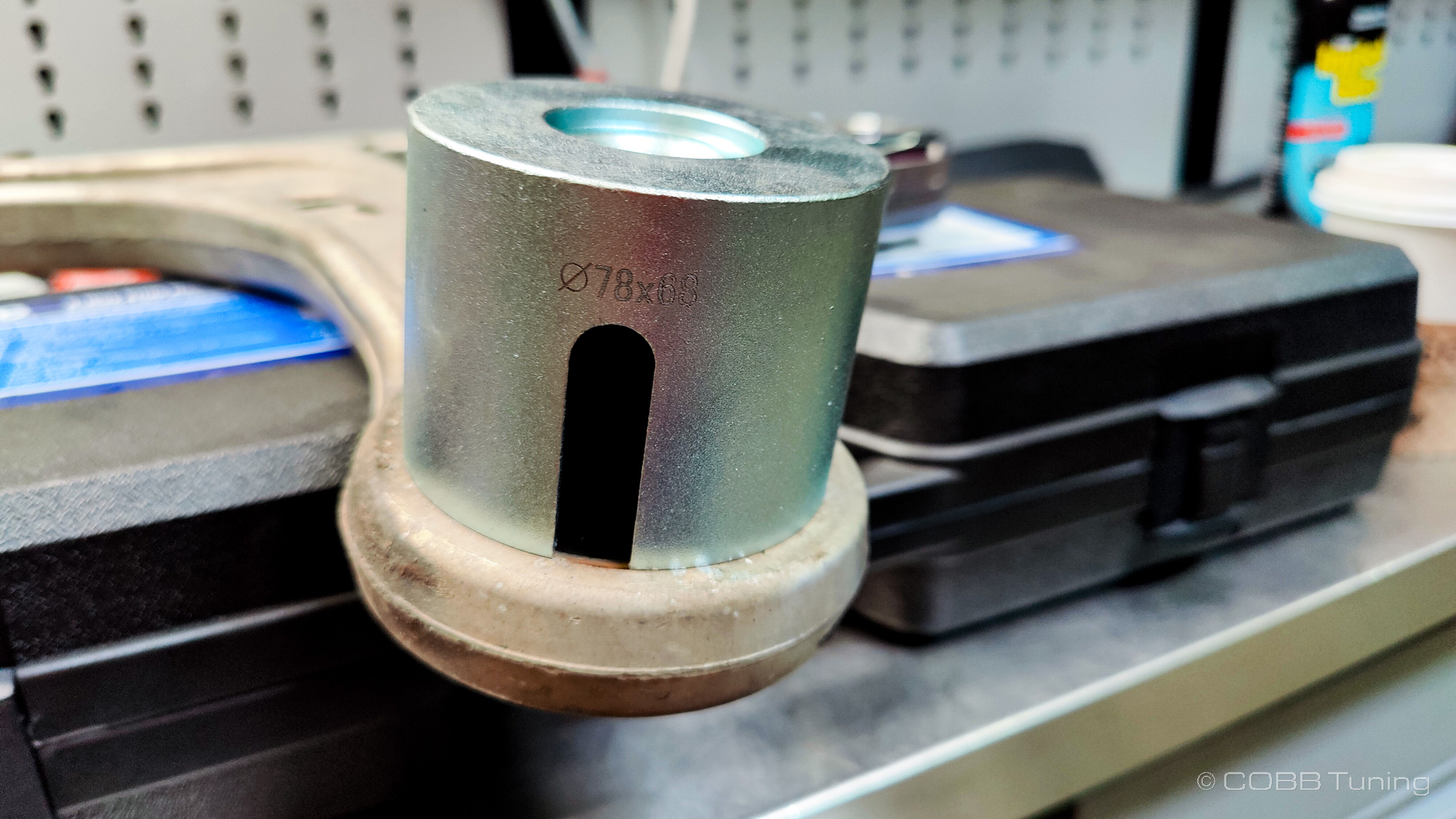
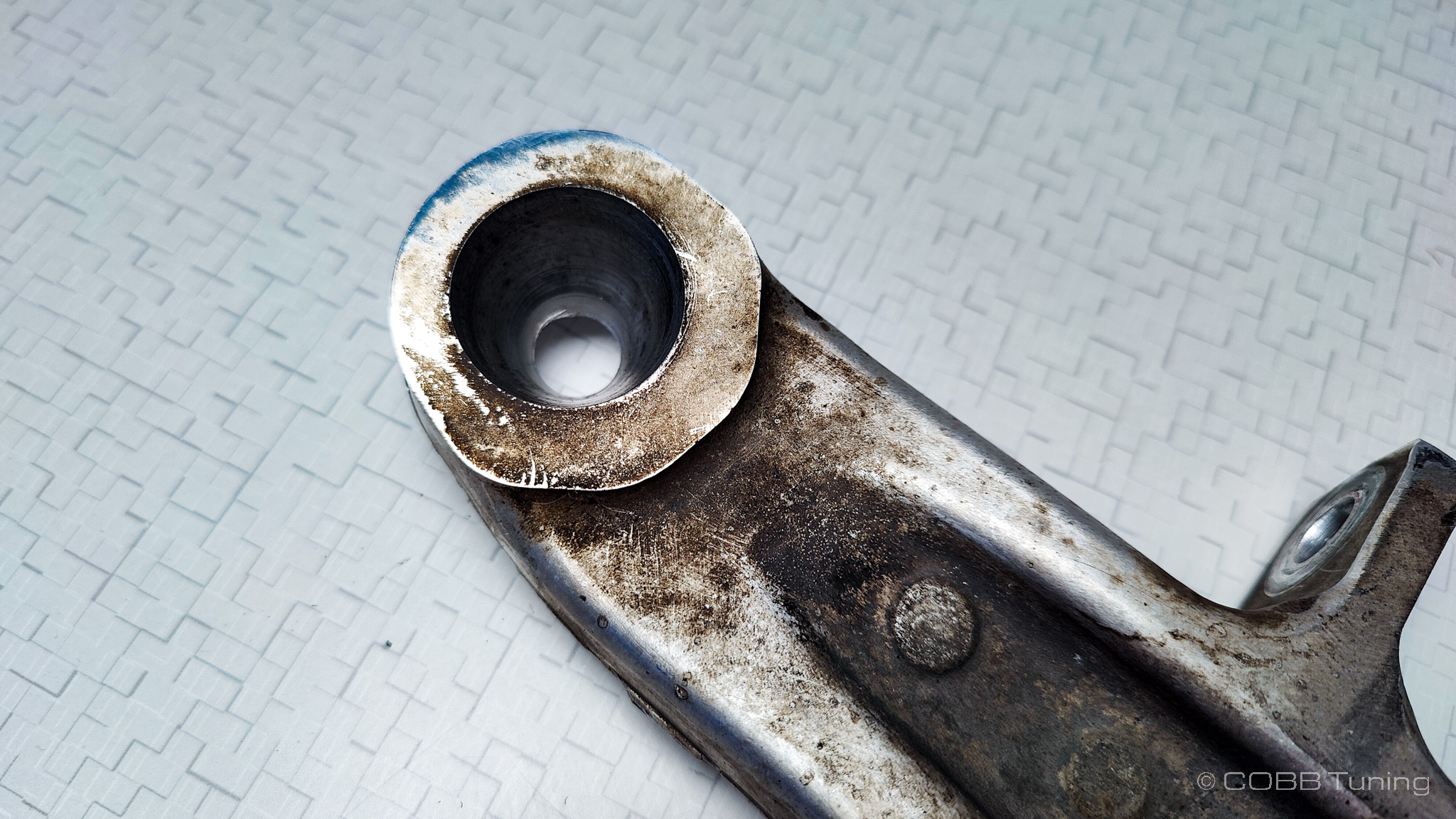
- Using an appropriate tools, remove the bushing from the control arm. There are simple kits you can rent at many parts stores if you don't have access to a press. Many shops will also press bushings for you fo ra small fee. However keep in mind this is an aluminum control arm and if you lever age from the wrong point you may crack the casting. It's equally important to make sure that the bushing cup you use to push it out matches the size of the metal portion of the bushing without being too large, otherwise you'll force the arm open too far for the new bushing to be tight.
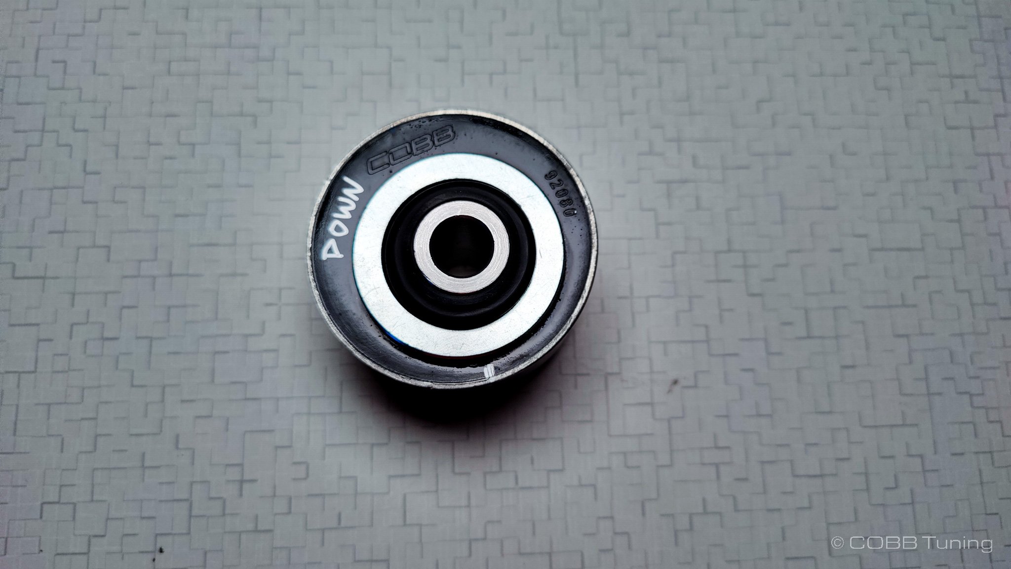
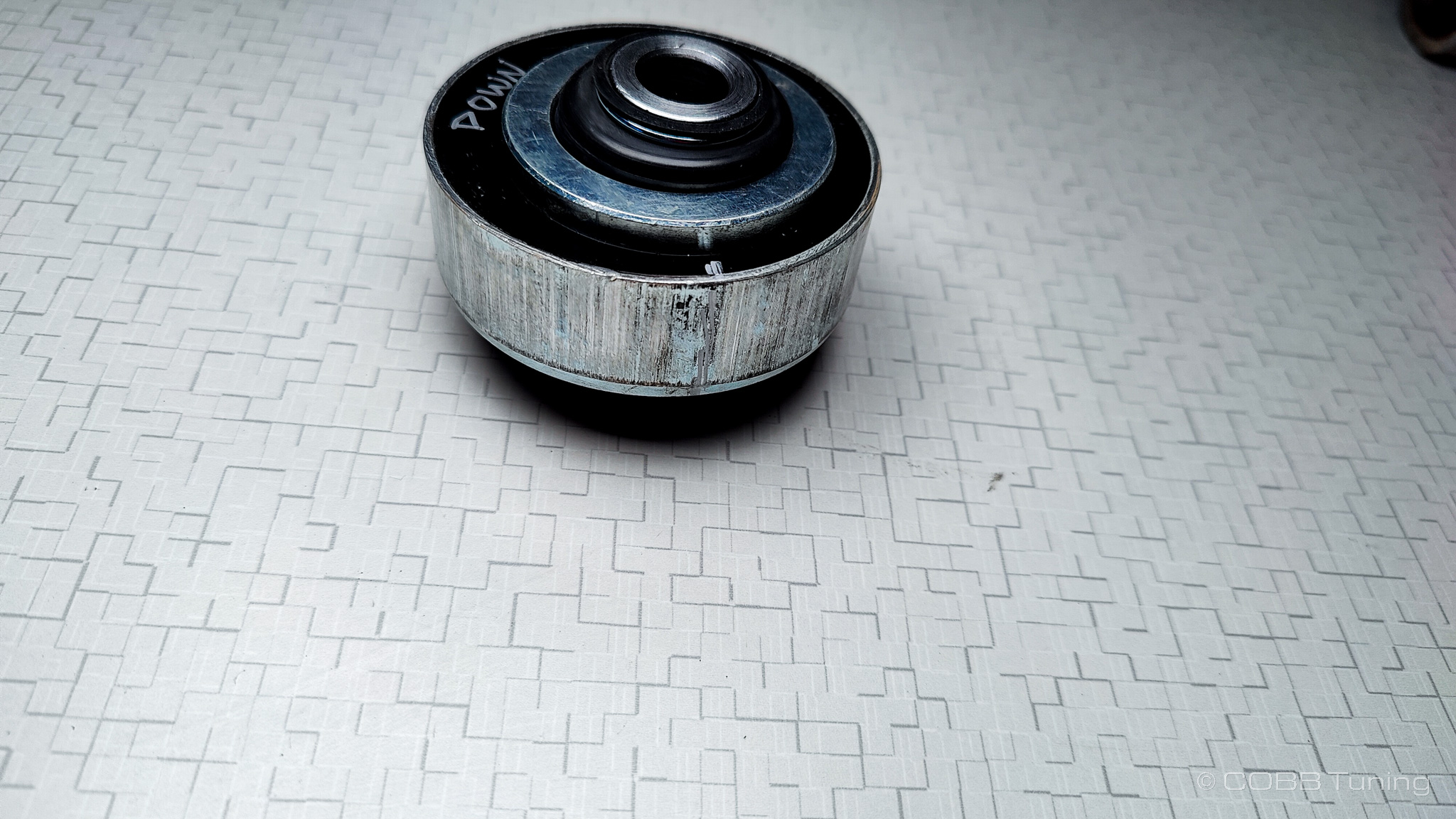
- When pressing it back in the stock style bushing (without added caster) can simply be pressed in paying attention to which side is the top and bottom. The side marked Down would be towards the ground, while the side marked Up would be towards the car.
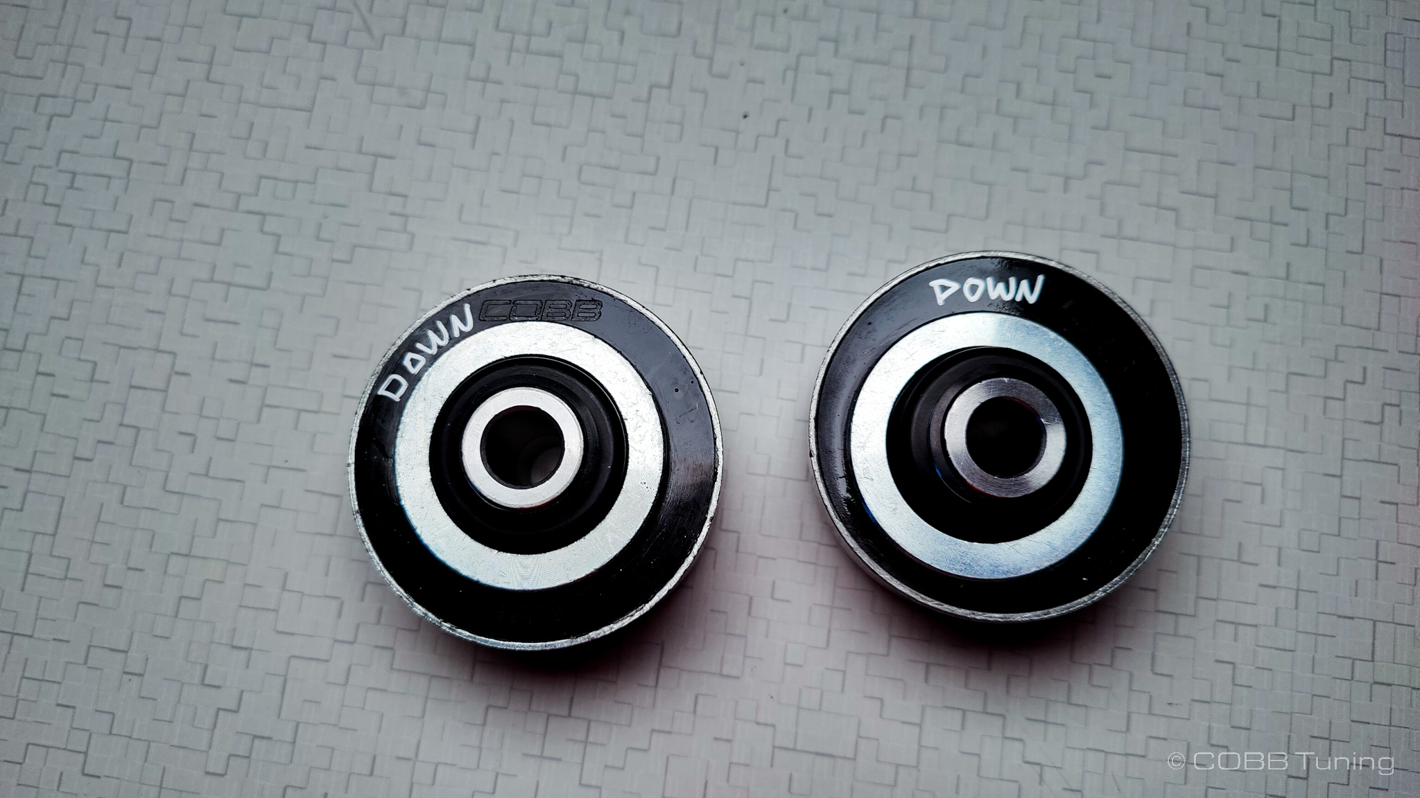
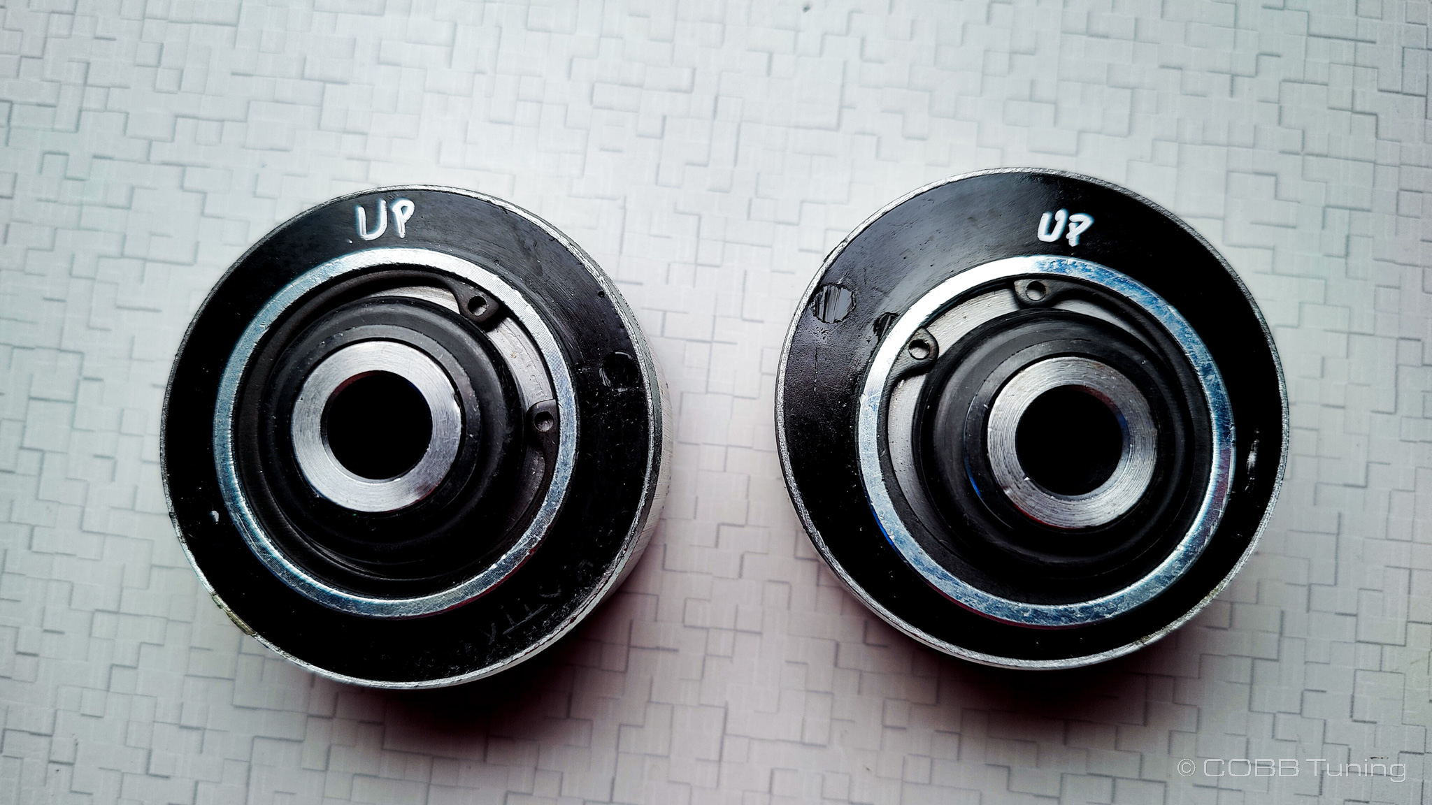
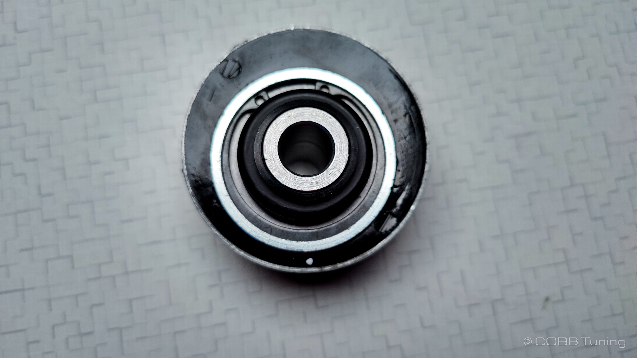
- If you're installing the bushings with added caster you'll need to line them up properly. Unfotunately the control arm doesn't have any magical marks to make lining this up exact. The hole throug hthe bushing is offset closer to one side, you'll want to mark that side clearly so you can check it as you press it in. This should be the side opposite the COBB logo on the offset bushings. Seen here marked on the bottom side of the bushing.
- I then transitioned the mark to the other side of the bushing trying to go over the metal with a slightly dried out silver sharpie (you'll have better luck with a black sharpie)
- The side with the COBB logo should go towards the same side of the arm as the tie rod end. Another way to put it would be that the bolt hole should go closest to the car side.
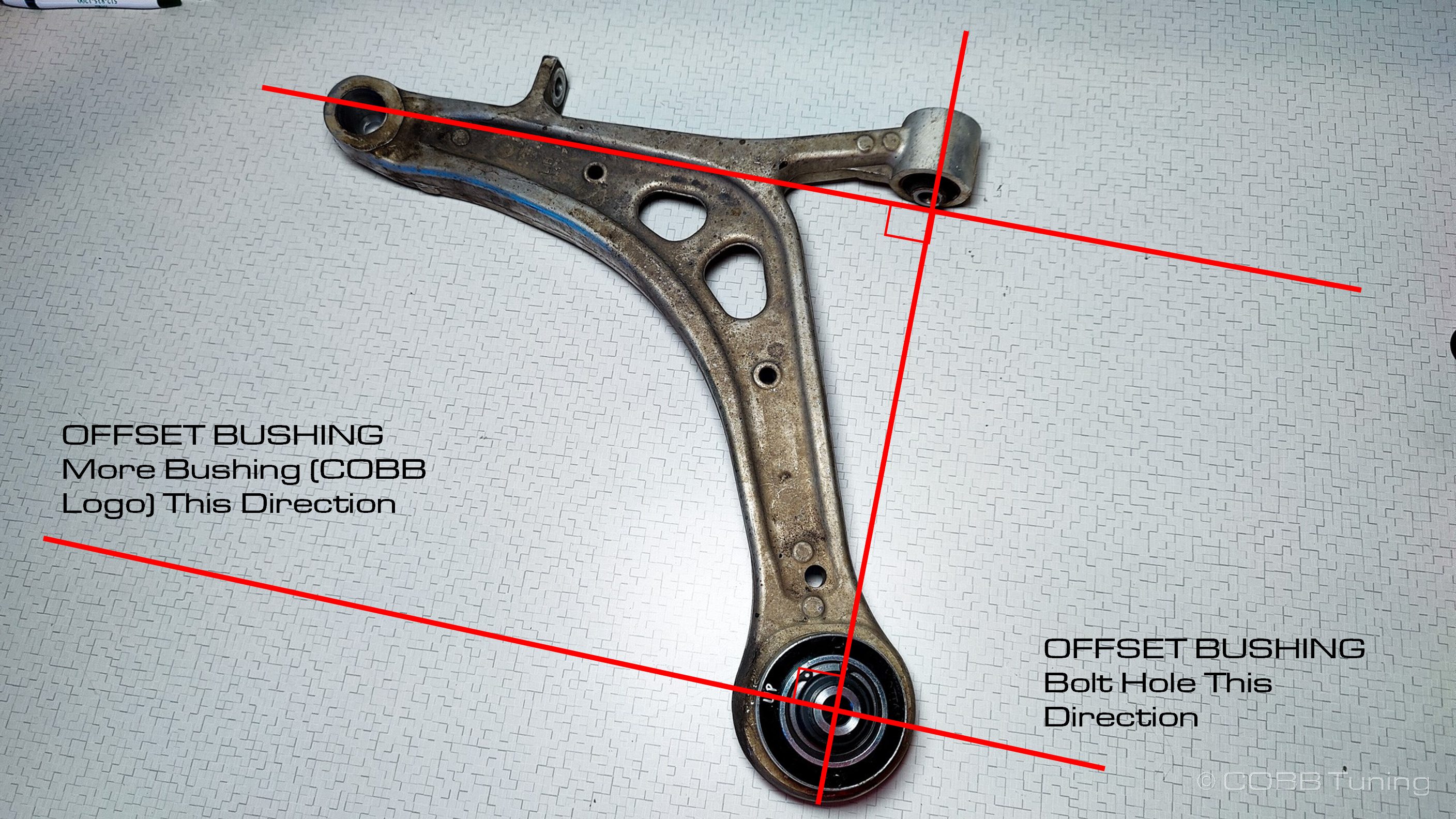
- Before pressing it in make sure you are putting the bushing in the right way one last time. The concave hole for the tie rod end will face upwards.
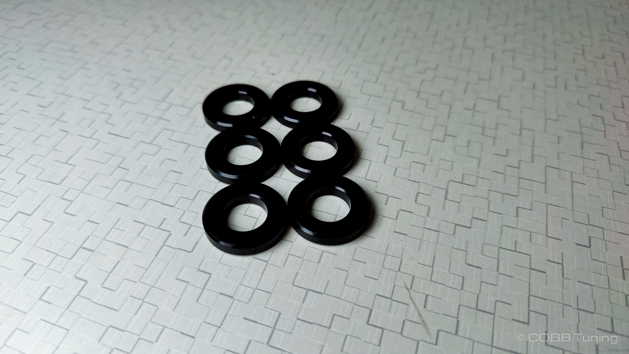
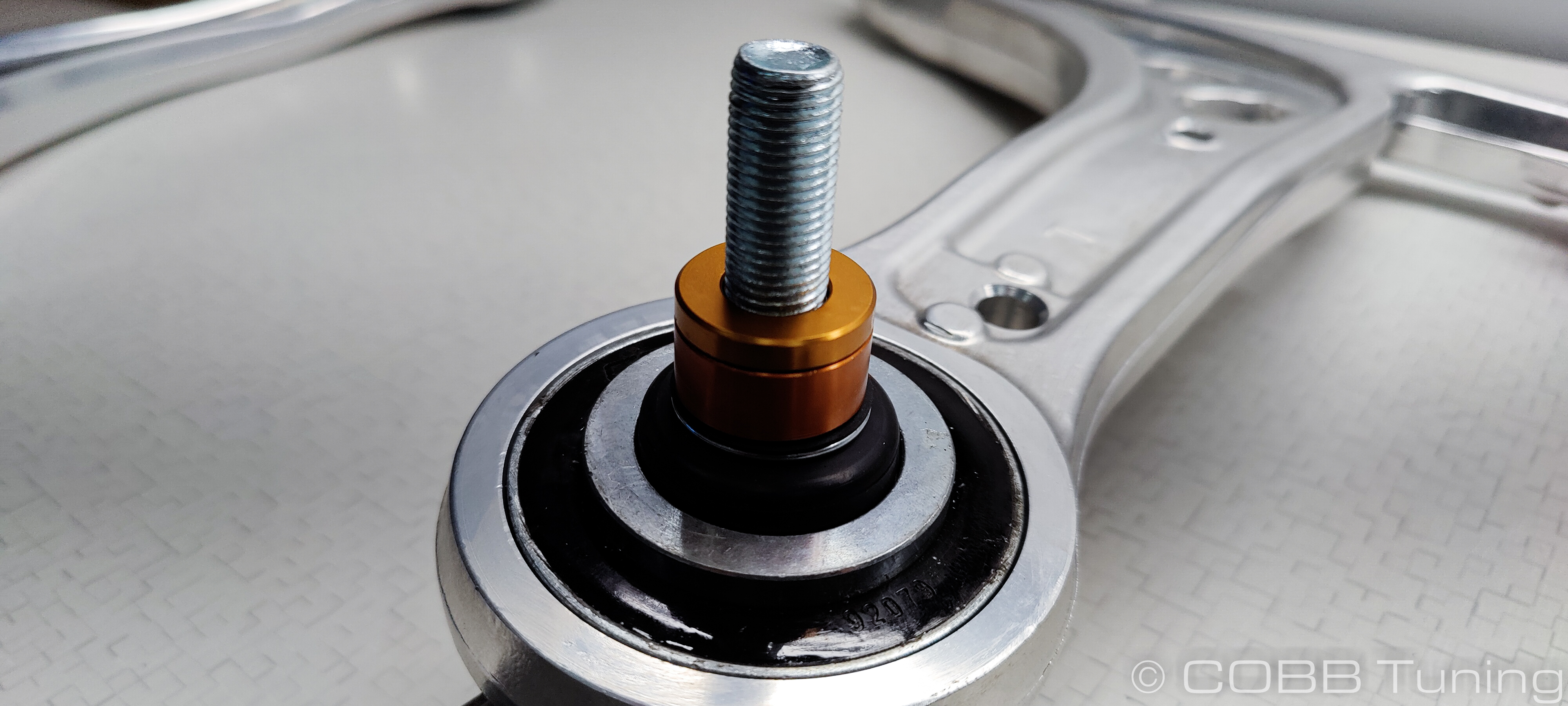
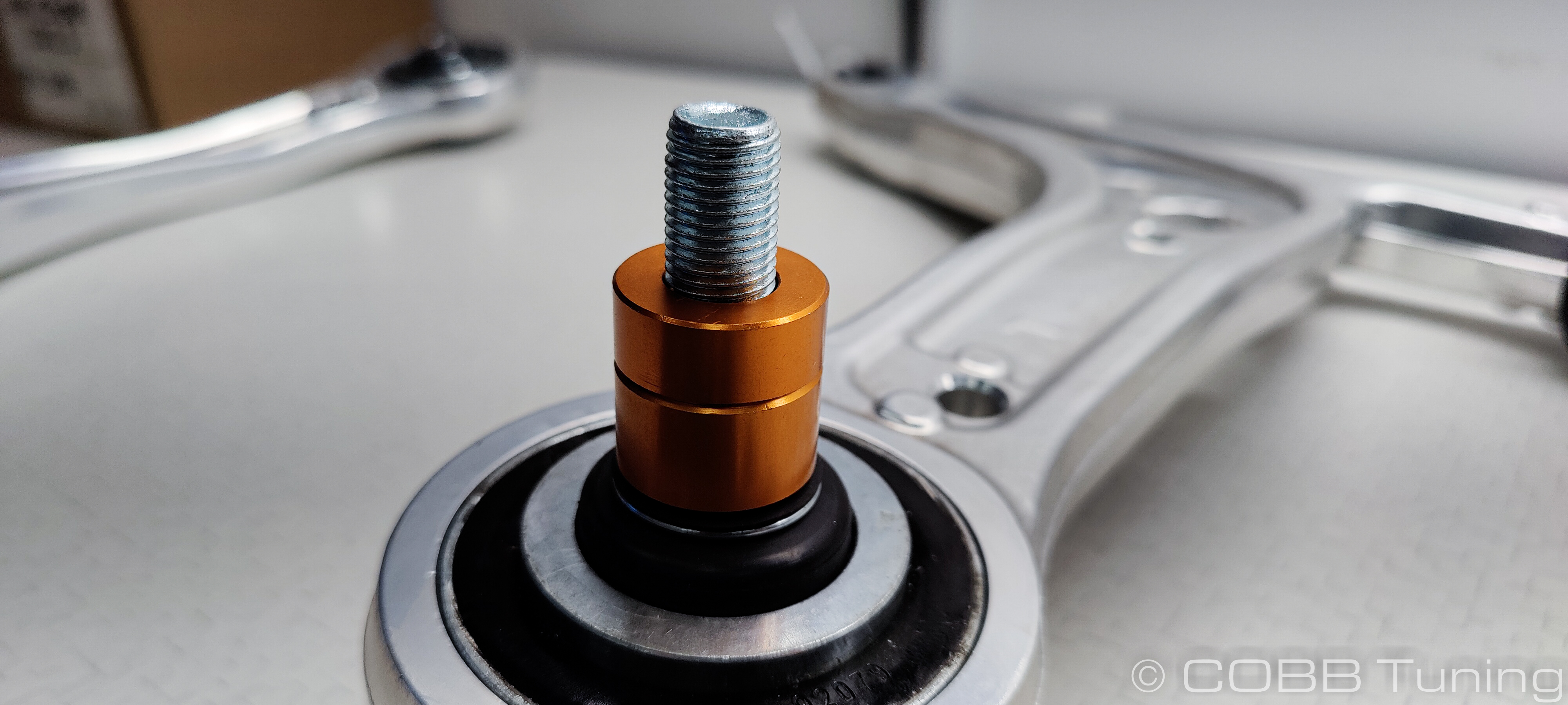
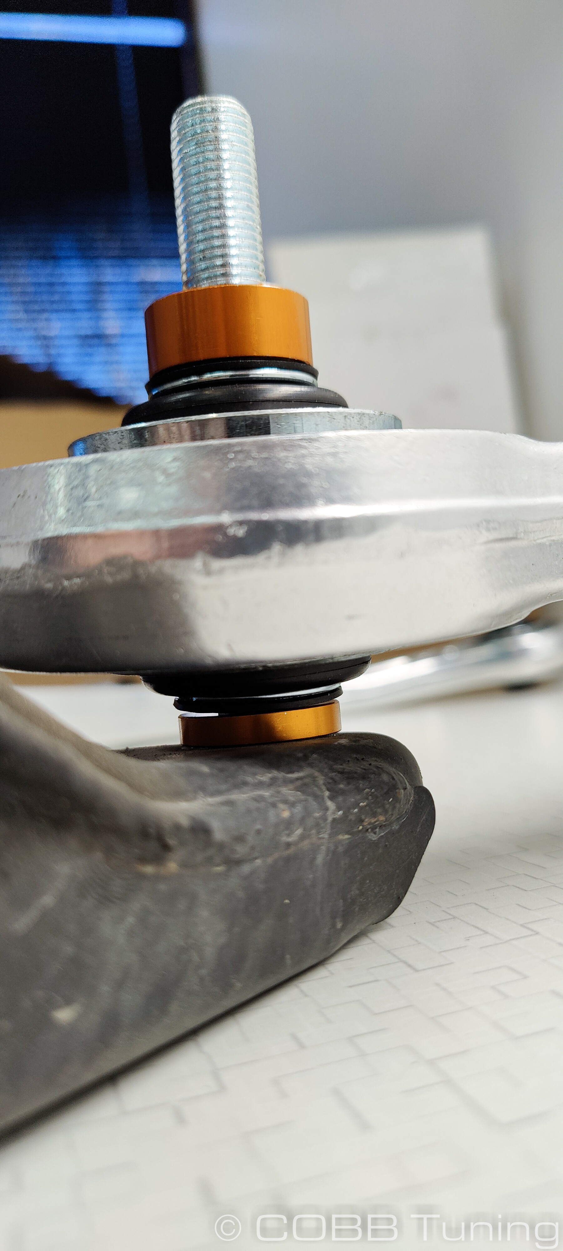
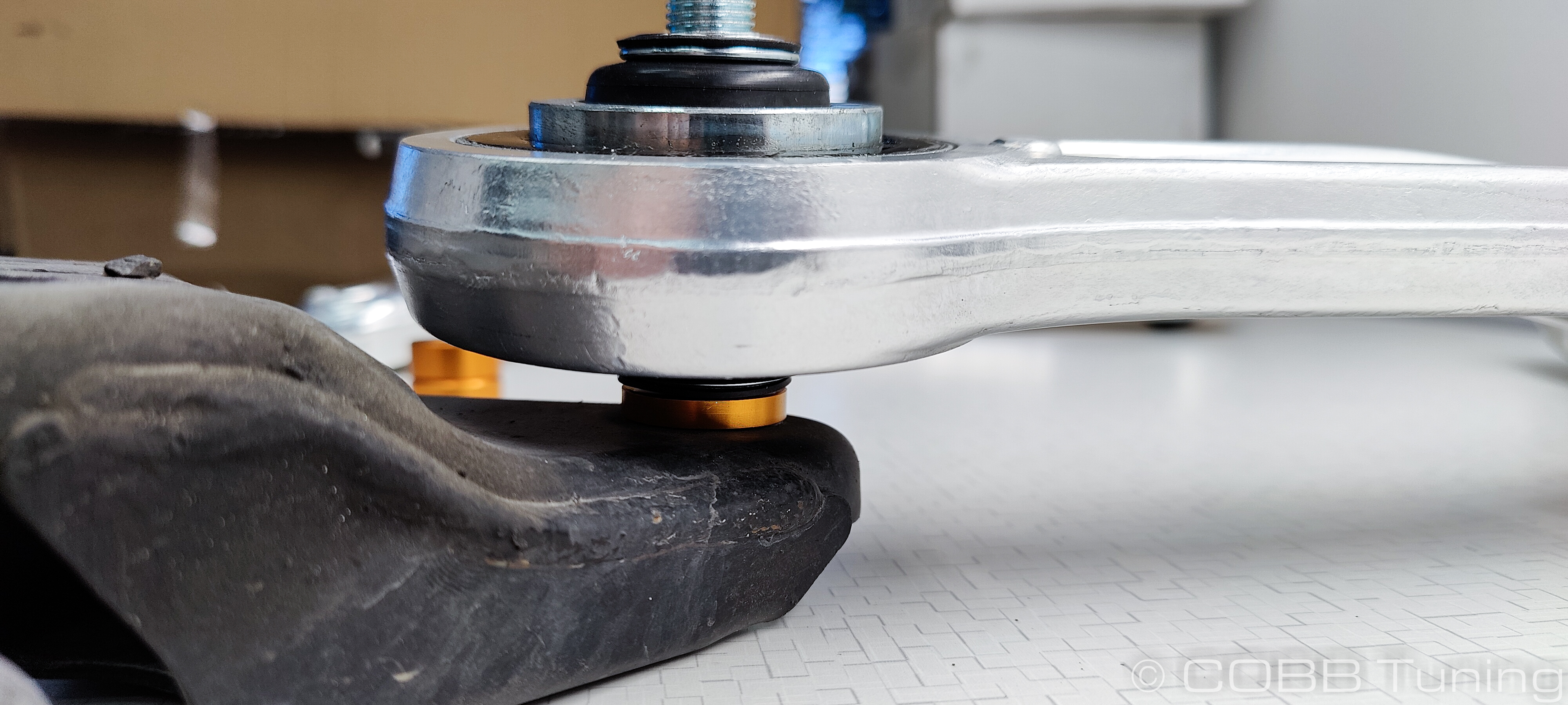
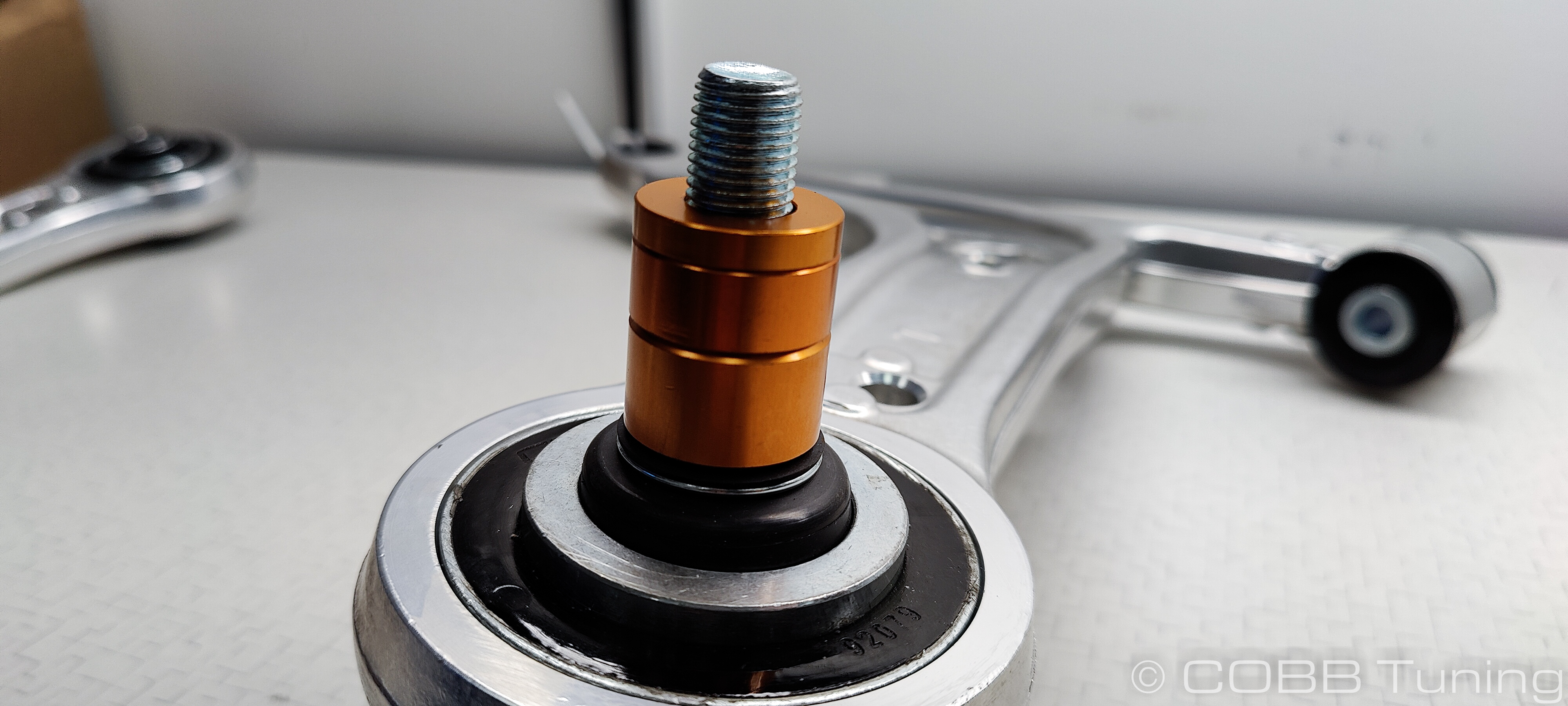
Spacer Sizing
![]()
OEM Style Handling
We recommend this setting for most users.
11-14 STI
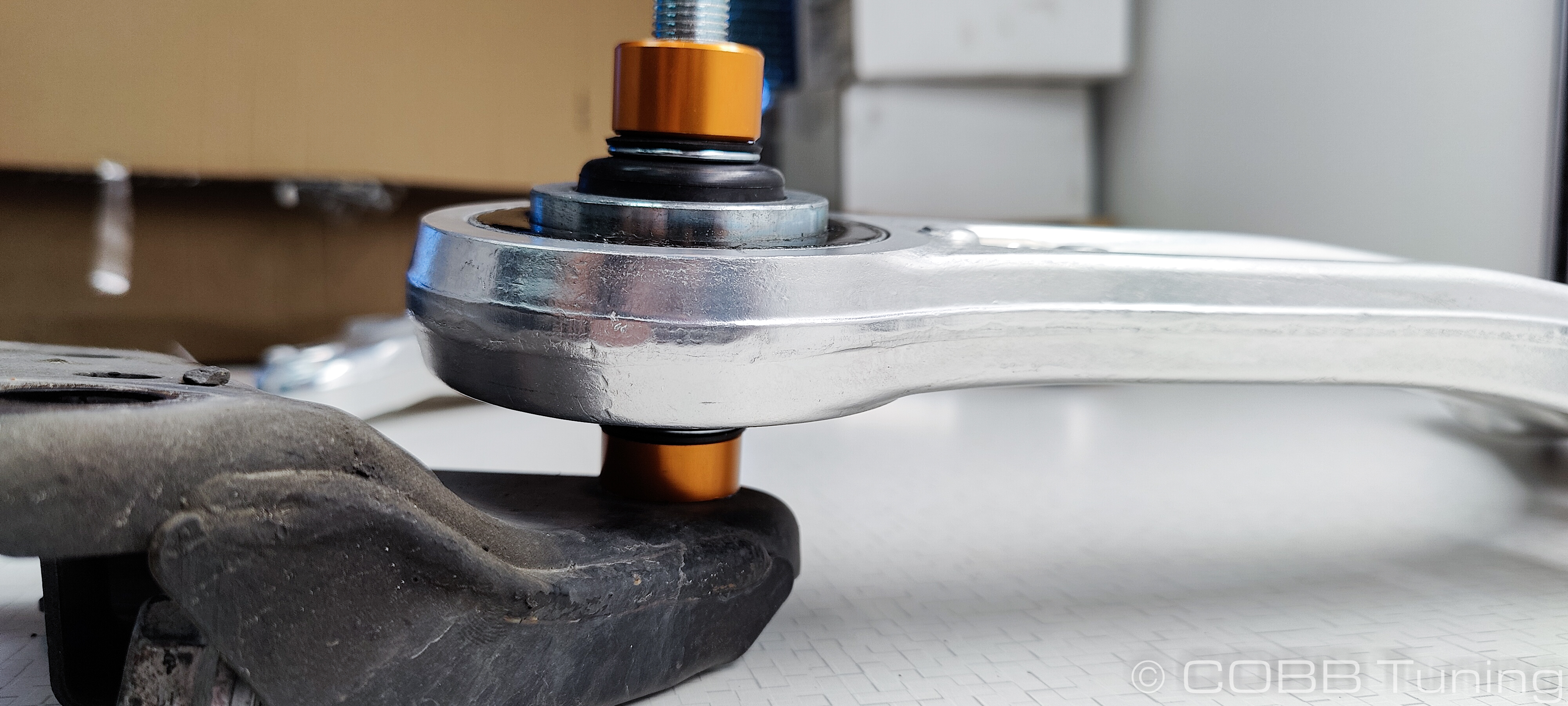
- Main bushing between arm and vehicle: 16mm spacer
15-21 WRX and STI
- Main bushing between arm and vehicle: 16mm and 11mm spacer stacked
Anti-Dive
11-14 STI
- Main Bushing between arm and vehicle: 11mm Spacer
- Between arm and support bracket: 5mm spacer
15-21 WRX and STI
- Main bushing between arm and vehicle: 16mm spacer
- Between main bushing and support bracket: 11mm spacer
Anti-Lift
11-14 STi
- Main Bushing between arm and vehicle: 16mm spacer
- Between support bracket and vehicle: 5mm spacers
15-21 WRX and STI
- Main Bushing between arm and vehicle: 16, 11, and 5mm spacers stacked
- Between support bracket and vehicle: 5mm spacers
Installation
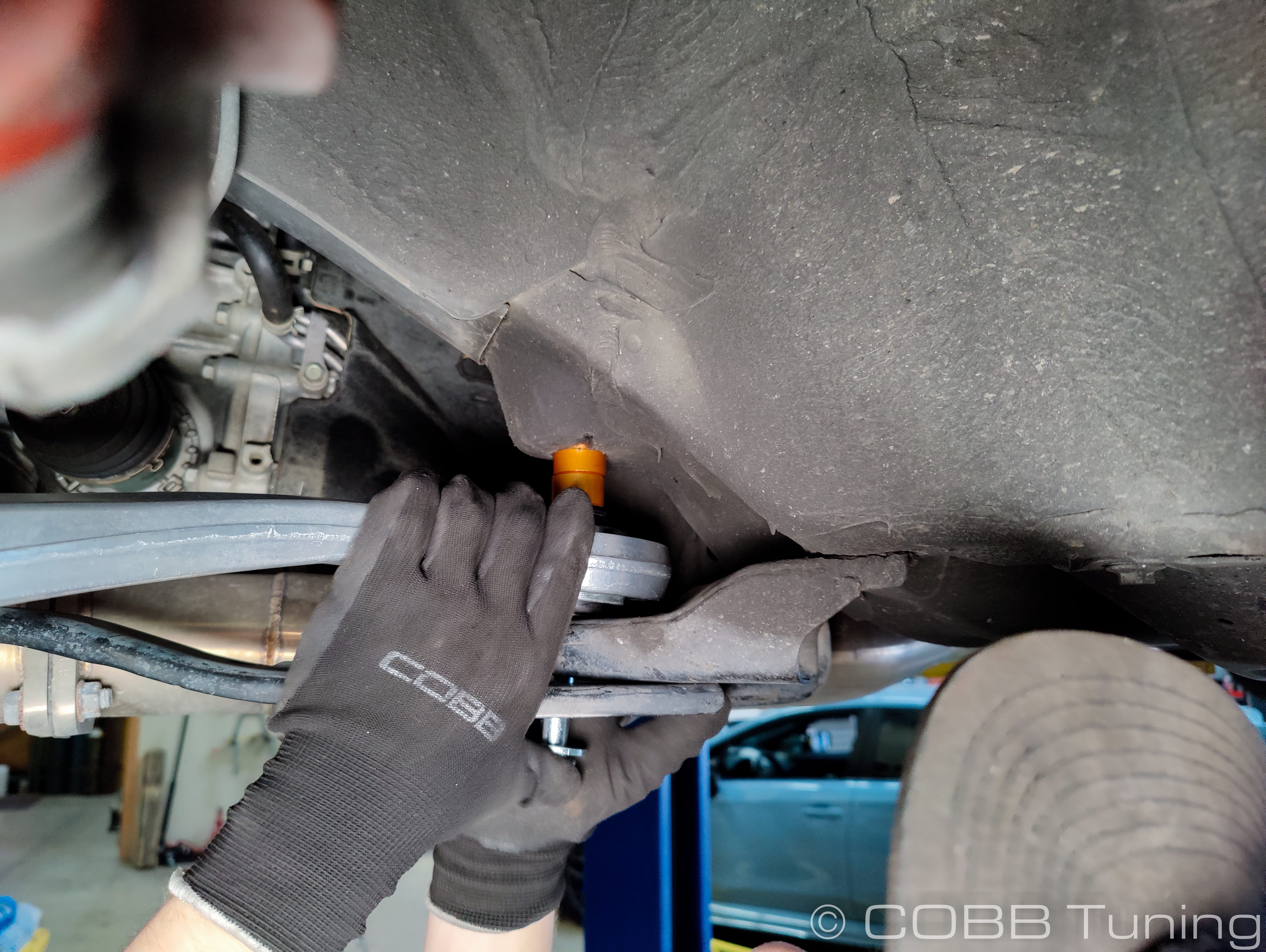
- Start by installing the rear upward facing bushing onto the car using the spacers from the previous step. It's best to get things in place but leave it loose for now.
- Reinstall the front horizontal bushing with the bolt going in towards the rack.
- At this point the outer balljoint should fall into place on the control arm if you just swing it upwards. Sometimes lifting the spindle a little bit can help it drop into place.
- From here you can torque snug the control arm and control arm bracket bolts down, and reinstall the cotter pin for the ball joint castle nut. Tighten it to 36.9 ft-lb or 50N-M
- Loosely install the sway bar end link on one side before installing it on the other side. Then tighten them both back up to 44.3 ft-lb (60Nm)
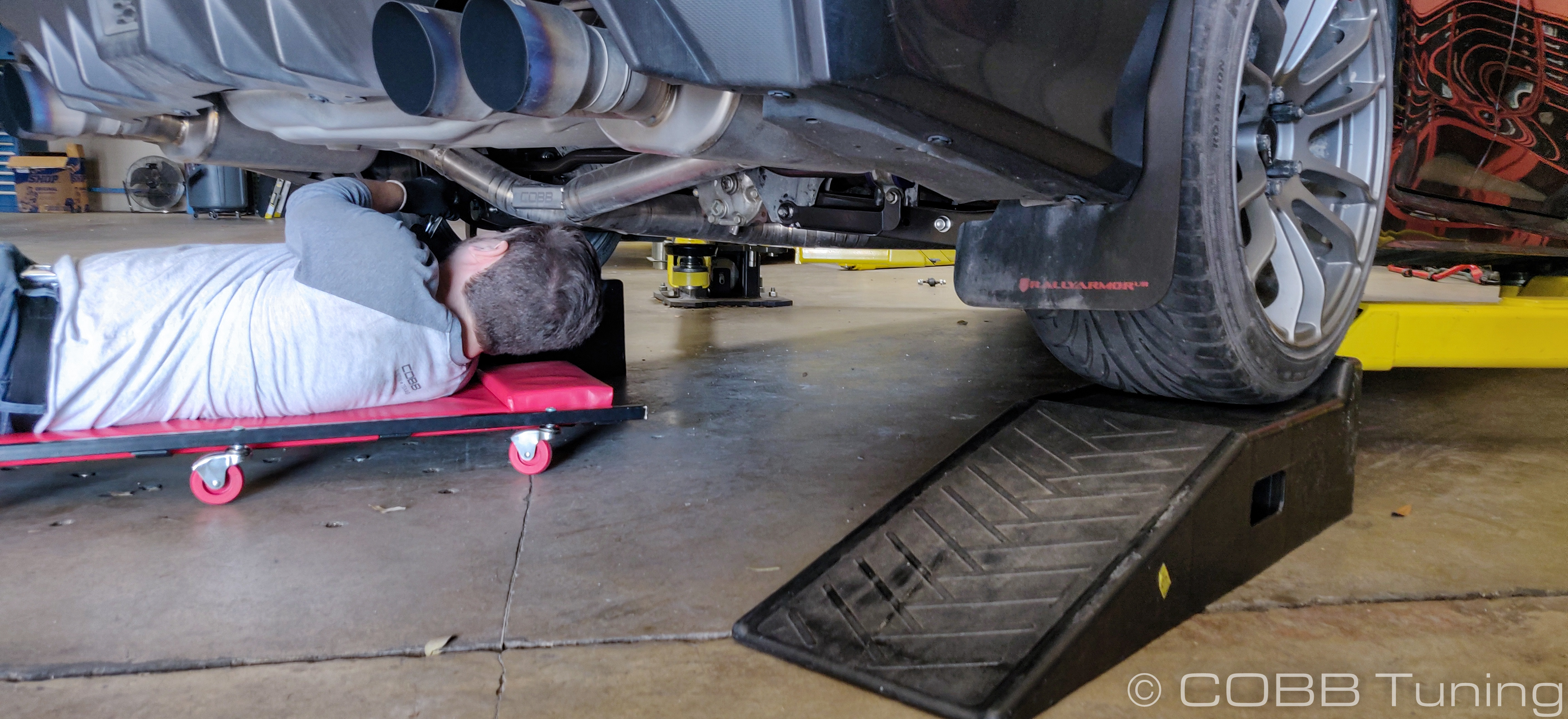
- In order to prevent any bushing binding we want to wait and torque the control arm down while the weight is resting on the vehicle's wheels. This can be done by either jacking up on the control arm to put weight on the suspension, or by reinstalling the wheels and setting the car on a wheel support or ramp. Either way make sure to keep the vehicle properly balanced and supported while doing this.
- With the vehicle resting on it's own weight, it's time to torque the control arm down properly. The front horizontal bushing gets torqued to 70 ft-lb (95 Nm).
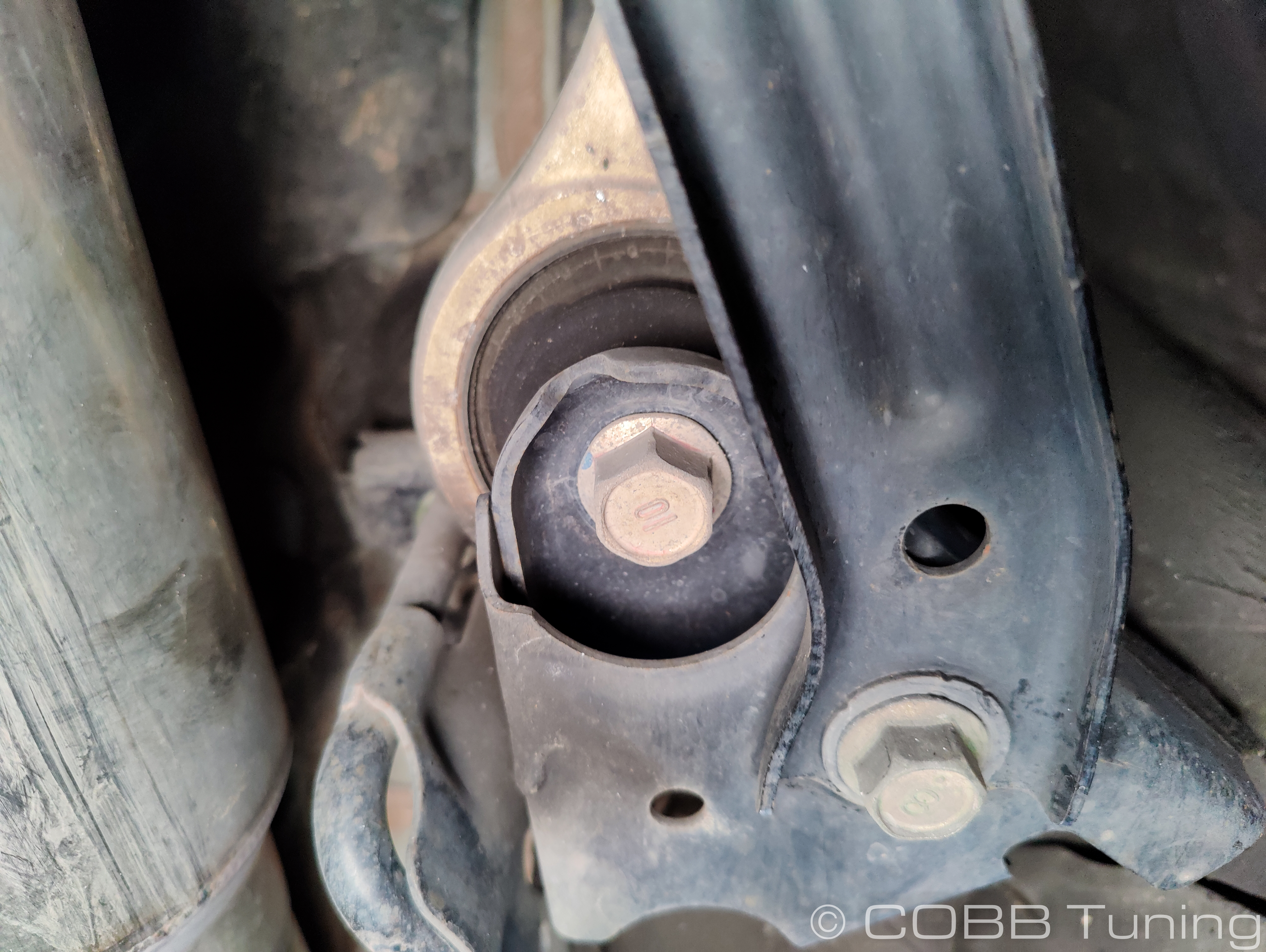
- The main vertical 19mm bolt going through the rear bushing gets tightened to 103.3 ft-lb (140Nm)
- The two shorter 19mm bolts for the rear bushing bracket get tightened to 110 ft-lb (100Nm)
- The 17mm bolt for the support brace going to the rear bushing support bracket gets tightened to 73.8 ft-lb (100 Nm)
- Take your vehicle to get an allignment before any hard driving or driving at speed.
Front Suspension Torque Specs
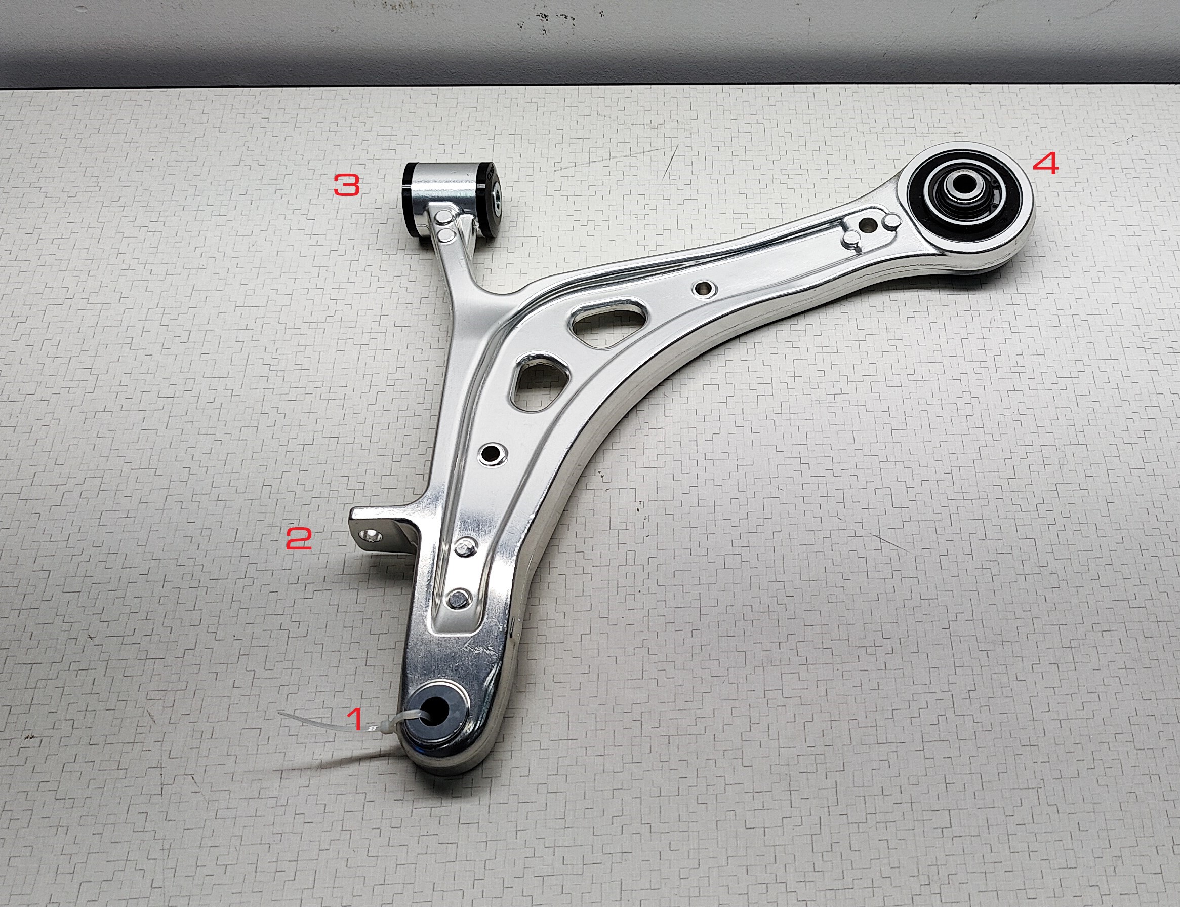
| 1 | Lower BallJoint | 36.9 ft-lb | 50Nm |
| 2 | Front Swaybar Endlink to Control Arm | 44.3 ft-lb | 60Nm |
| 3 | Control arm front horizontal bushing | 70 ft-lb | 95Nm |
| 4 | Control arm rear vertical bushing | 103.3 ft-lb | 140Nm |
| 5 | Shorter bolts for control arm support bracket | 110 ft-lb | 150Nm |
| 6 | Control arm support bracket brace | 73.8 ft-lb | 100Nm |
| 7 | Wheels | 88.5 ft-lb | 120Nm |
Links
Contact Us:
COBB Customer Support
Web Support and Tech Articles: COBB Tuning Customer Support Center
Email: support@cobbtuning.com
Phone support available 9am to 6pm Monday-Thursday. 9am to 4pm Friday (CST)
866.922.3059
return to www.cobbtuning.com
Related content
Copyright 2025 © COBB Tuning Products LLC. All Rights Reserved. | www.cobbtuning.com