SUB000FSYS / SUB000FSFF - COBB Fuel Rail and Fuel Line Installation Instructions
- Former user (Deleted)
- Brandyn Mowat

SUB000FSYS / SUB000FSFF - COBB Fuel Rail and Fuel Line Installation Instructions
2008 - 2021 Subaru STI
Congratulations on your purchase of the COBB Tuning fuel rails and fuel lines package! The following instructions will assist you through the installation process. Please read them BEFORE beginning the install to familiarize yourself with the steps and tools needed. If you feel you cannot properly perform this installation, we HIGHLY recommend you take the vehicle to a qualified and experienced automotive technician.
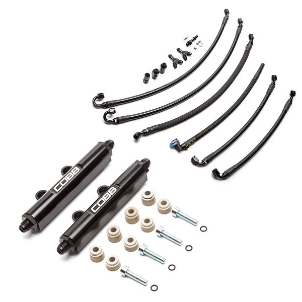
Parts List
- x5 Fuel lines (labeled 1-5)
- CAUTION: These lines have a 3" bend radius. If you bend the lines significantly more, you may damage them! At no point does our suggested routing have more than a 3" bend.
- x1 90 Degree 3/8" fuel line (unmarked, for use when routing directly to FPR on return line)
- x2 Y-blocks
- x1 3/8" FI Fuel line adapter
- x1 Female to female adapter
- x1 5/16" Quick connect (push on)
- x2 Fuel rails
- x4 Small spacers (marked in bag labeled "S")
- x4 Socket head bolts (for assembling the fuel rails)
- x4 O-rings (for assembling the fuel rails)
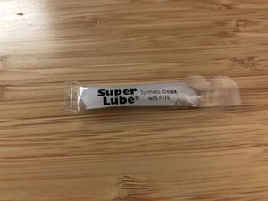
- x1 Super lube packet
Tools Needed
- WRX 2002 - 2007
- WRX STI 2004 - 2020
- Forester XT 2004 - 2008
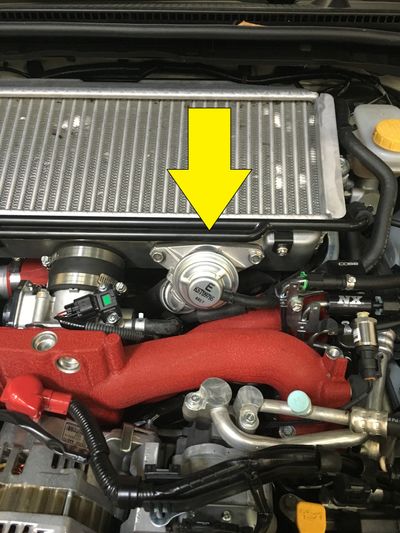
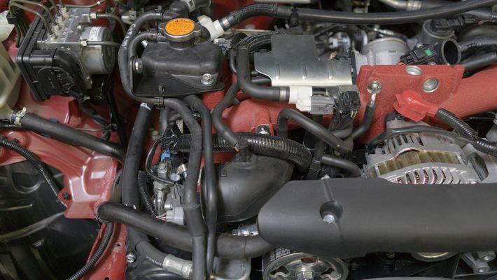
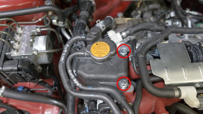
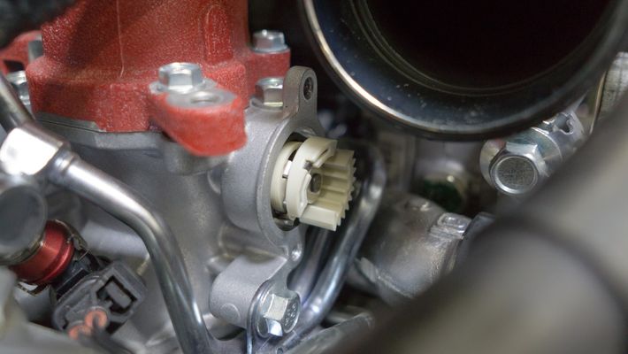
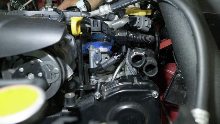
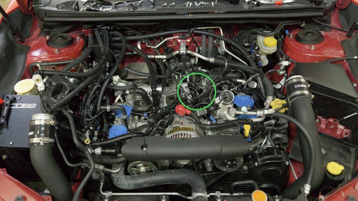
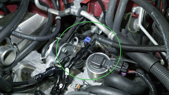
- Locate your stock bypass valve.
- Using a pair of pliers, remove the return line from the bypass valve.
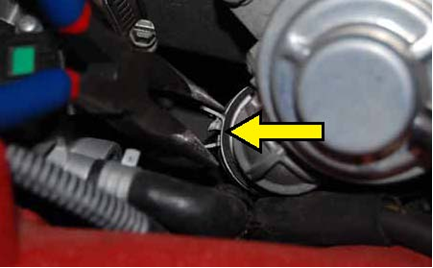
- Remove the vacuum line from the factory bypass valve.
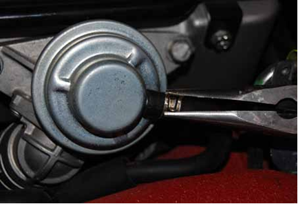
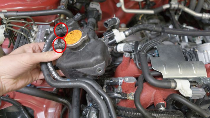
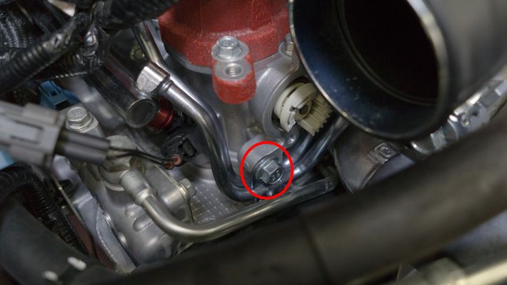
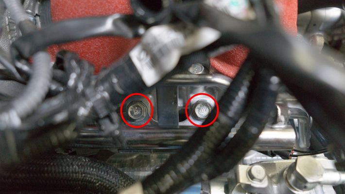
Using a 12mm socket with ratchet, remove the 2 bolts that hold the bypass valve in place and remove it from the car.
TIP: Make sure to keep an eye on the factory gasket behind the BPV. It can fall when you remove the valve and end up in difficult to reach locations!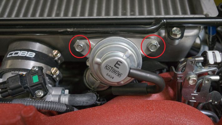
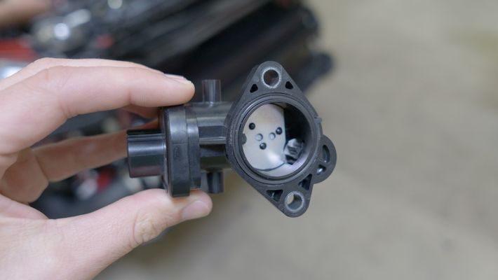
- Remove the bypass valve.
- Remove breather tubes from intercooler. Dikes can be helpful when removing the metal clamps or zip ties.
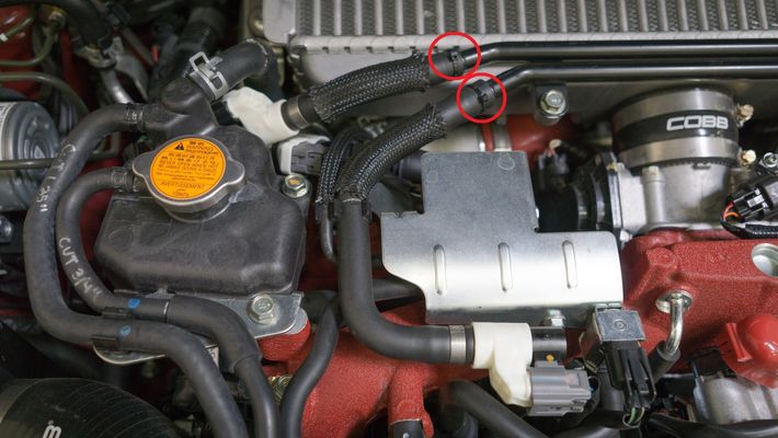
- Loosen the turbo outlet clamp using a screwdriver or appropriately sized socket (Typically 7-8mm) along with the (2) throttle body clamps using a screwdriver or 8mm socket.
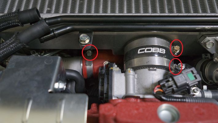
- Remove the two bolts holding the intercooler in place
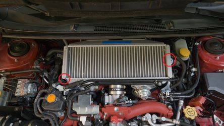
- Gently wiggle TMIC free from engine bay by sliding it back and then out. Be careful to not damage your windshield wiper cowl.
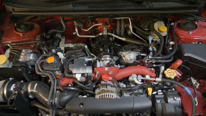
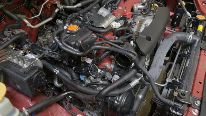
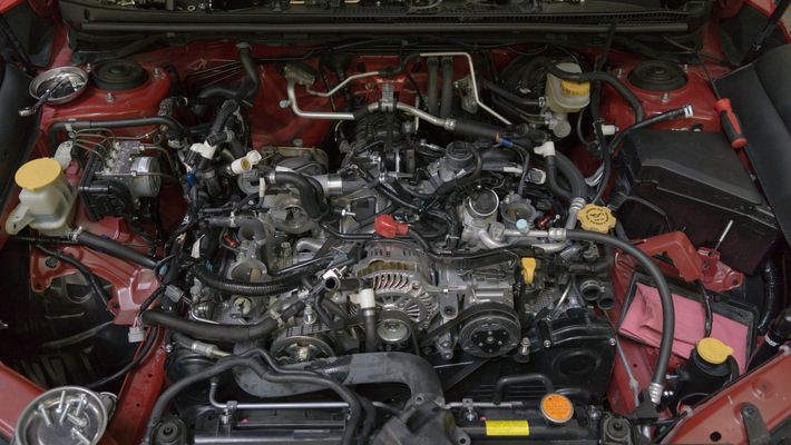
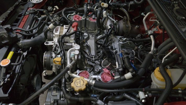
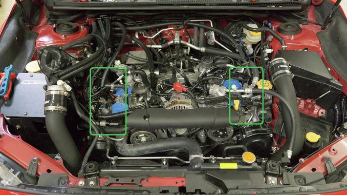
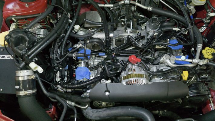
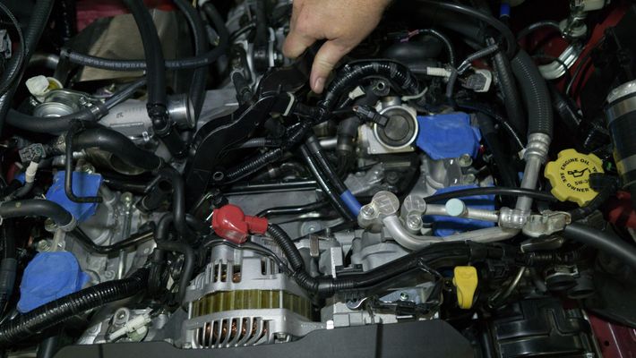
We perform this removal on a 2017 STI. While this is incredibly similar to the other models of EJ engines used over the years there may be small differences from vehicle to vehicle.
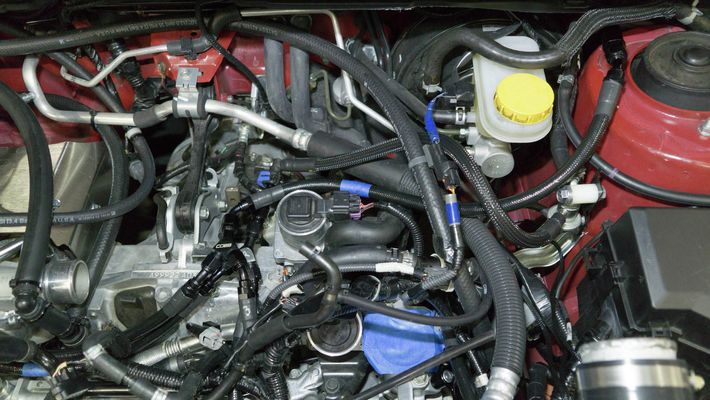
- You'll want to begin by taking plenty of pictures of your vacuum hose routing. This will be critical for when you're putting everything back together.
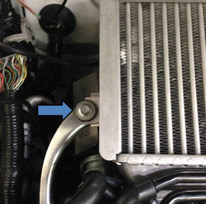
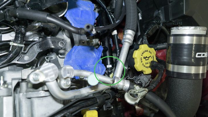
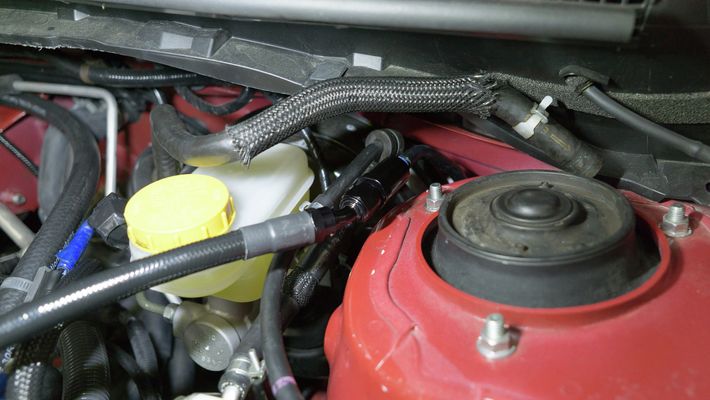
- With the car cool to the touch, we recommend draining the overflow coolant overflow reservoir. There is a small Phillips head bolt on the passenger side of the bottom of the radiator.
- Remove the coolant overflow reservoir by removing the (2) 12mm bolts.

Remove the top and bottom coolant lines going to the overflow reservoir using a pair of pliers.
Using a proper hose clamp can help reduce any spillage of fluids and reduce the amount of time required to bleed the cooling system later on.
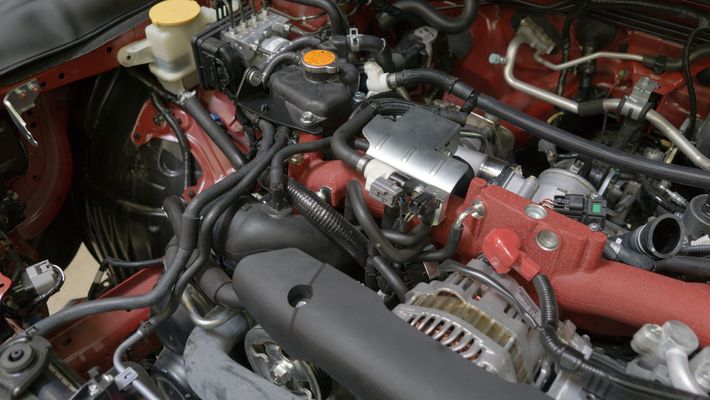
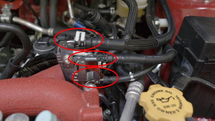
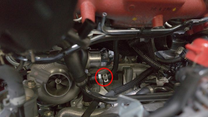
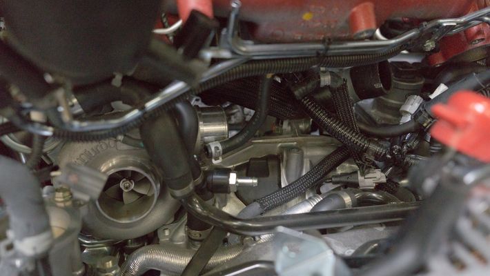
- Disconnect the electronic boost control solenoid (EBCS). There will be (3) connection points, 5/16" line to the turbo inlet hose, a 1/4" line to the wastegate, and an electrical harness (blue).
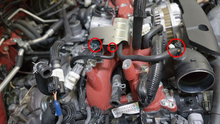
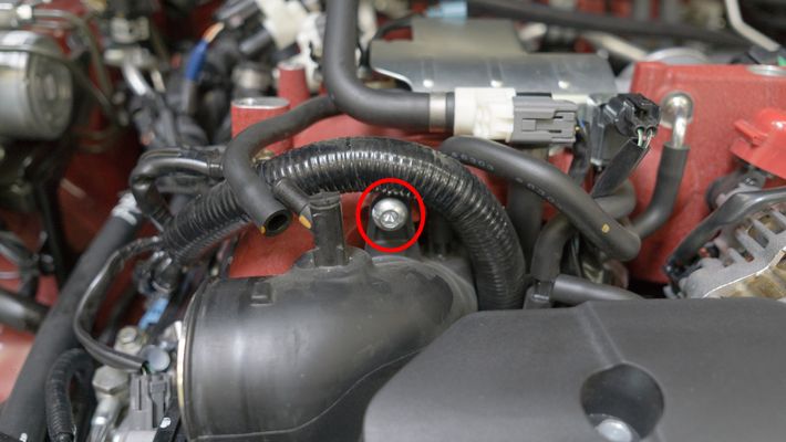
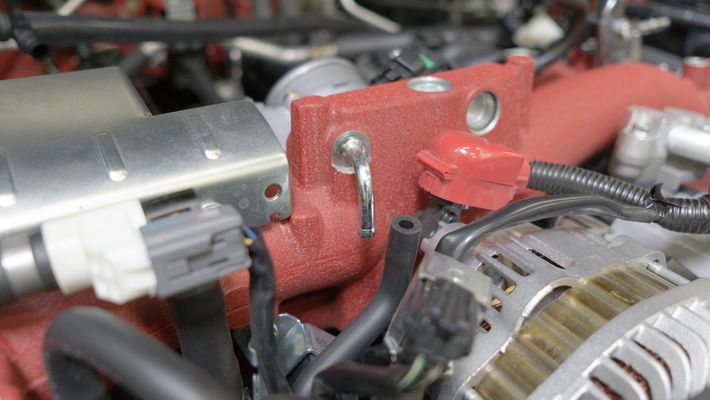
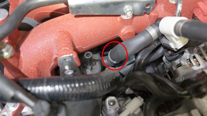
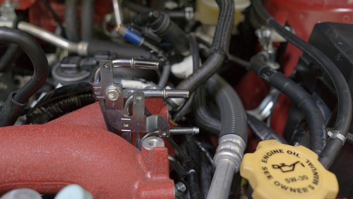
- Remove the 6mm hex head bolt on the front of the intake manifold holding the turbo inlet on.
- Remove the 10mm bolt on the rear of the EVAP sensor.
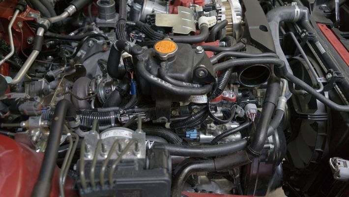
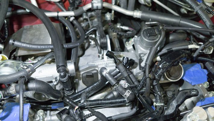
- Remove the intake manifold vacuum line.
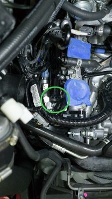
- Remove the 12mm bolt holding the purge valve on the intake manifold.
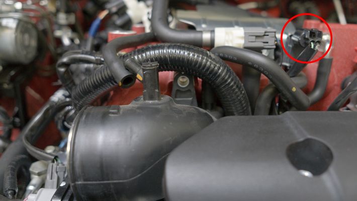
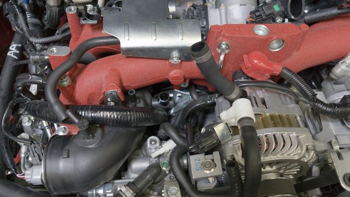
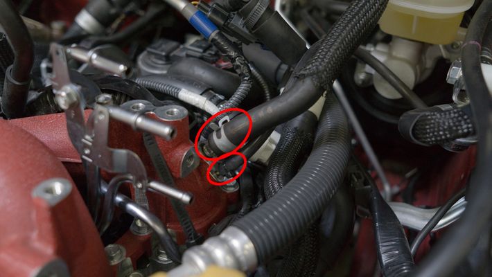
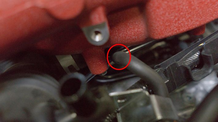
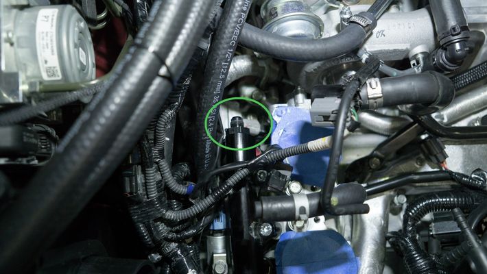
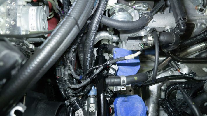
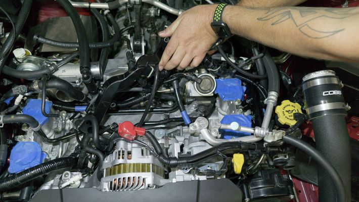
- Disconnect the 3/8" vacuum line from the top of the turbo inlet hose.
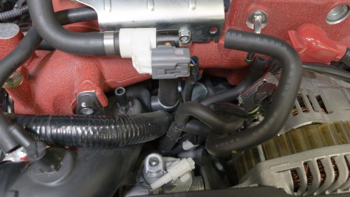
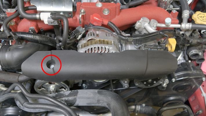
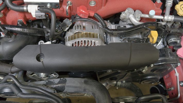
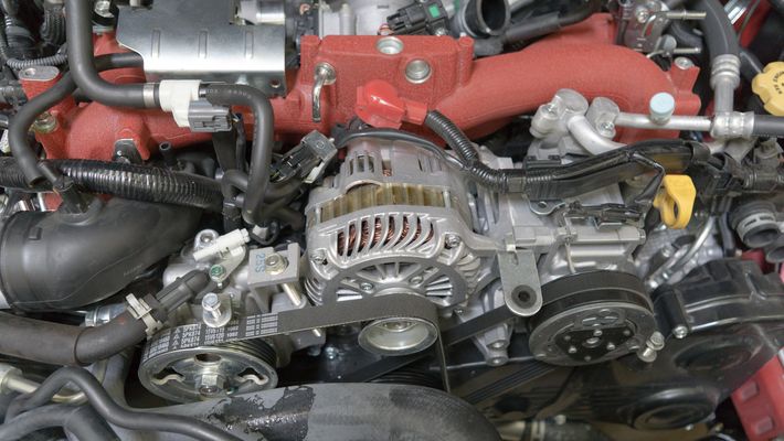
- Remove 10mm bolt securing the alternator cover. There is a push-type connector on the underneath the right-hand side.
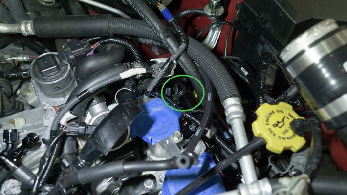
- Remove the PCV hose from the turbo inlet hose. You may need to cut off a metal clamp that is installed from the factory.
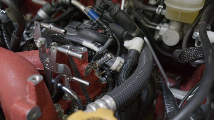
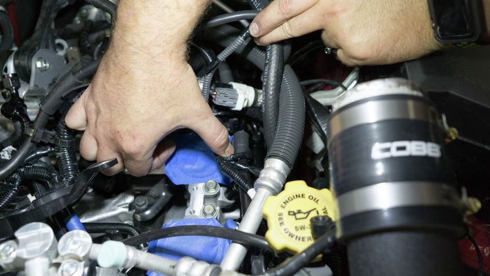
- Loosen the 10mm clamp securing the turbo silicone to the turbo.
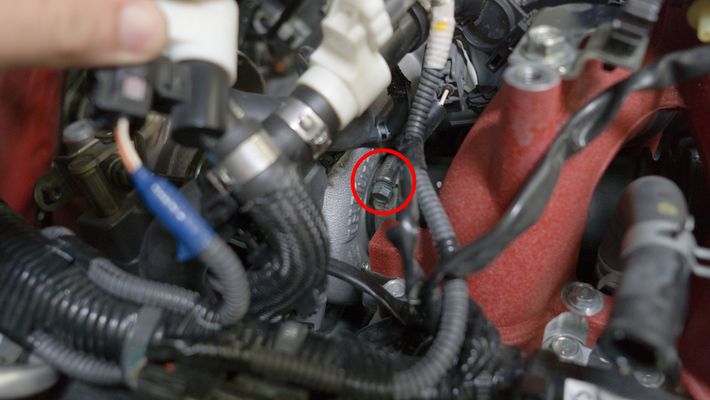
- Disconnect the 12mm bolt securing the ground.

- Remove the zip tie holding the wiring harnesses together.
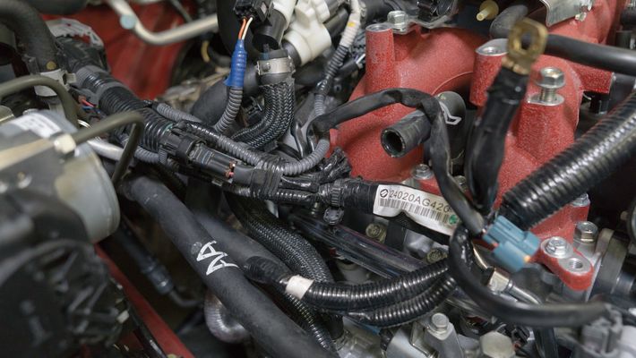
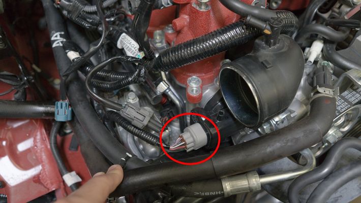
- Disconnect the MAP sensor, throttle position sensor wiring harness, and upper and lower coolant hoses.
- Disconnect the 12mm retainer bolt for the electrical harness on the back of the intake manifold.

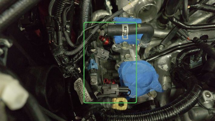
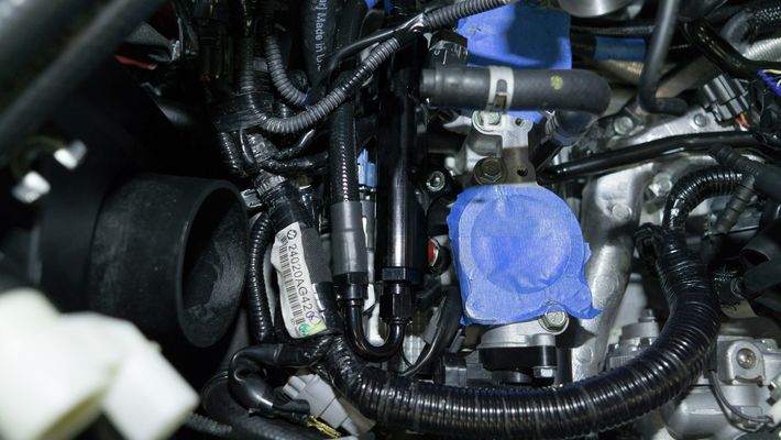
Disconnect the fuel lines from the intake manifold.
We typically recommend marking the lines with some sort of tape or colored zip tie to ensure you put them back in the same place.
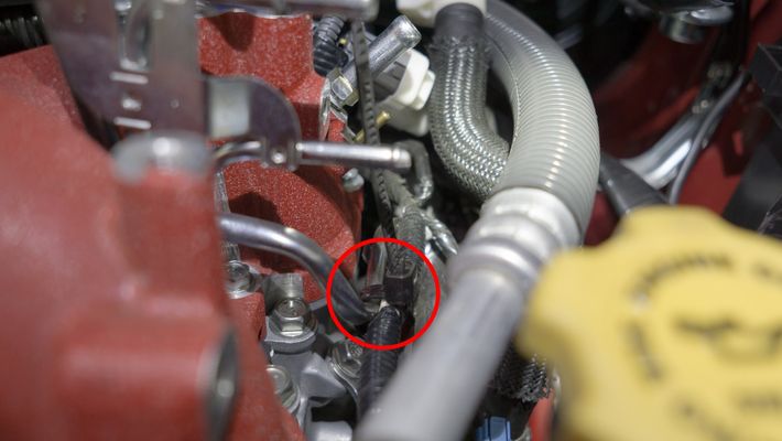
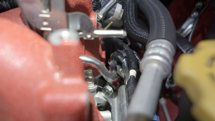
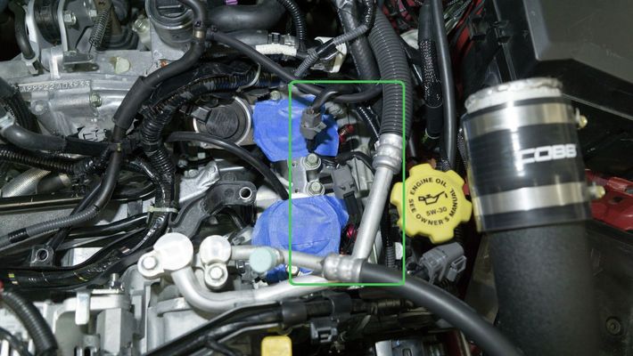
- Disconnect the brake booster hose and the fuel pressure regulator reference.
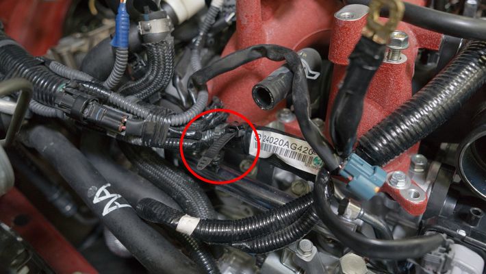
- Remove the zip tie holding the wiring harness to the fuel rail.
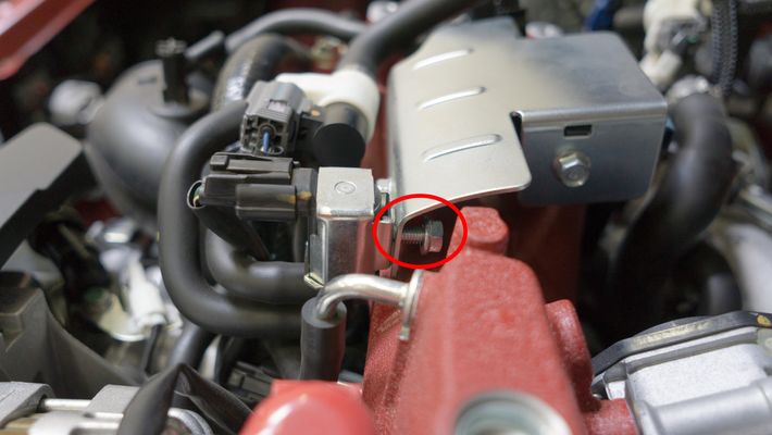
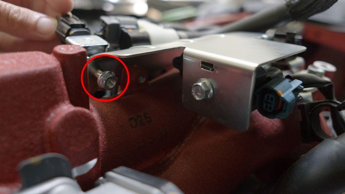
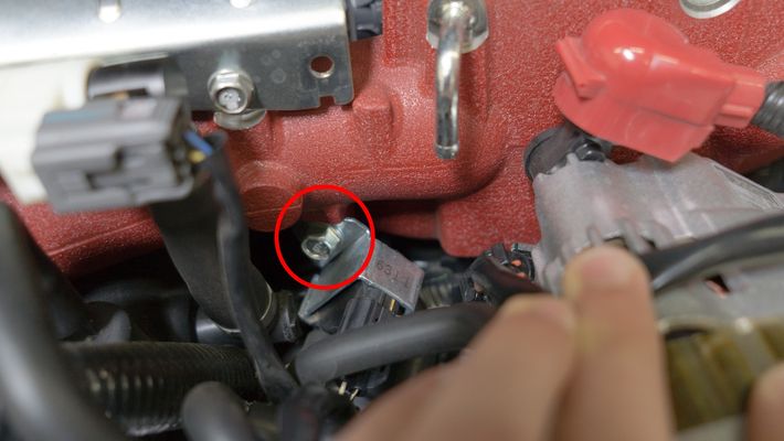
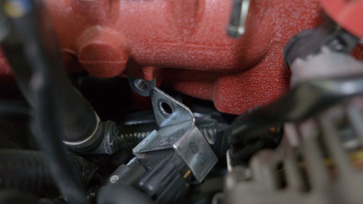
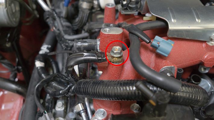
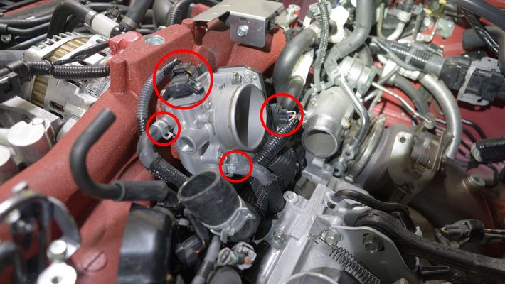
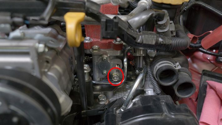
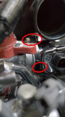
- Remove the 12mm bolt from the fuel rail bracket to the TGV.
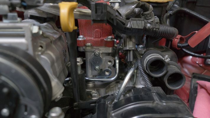
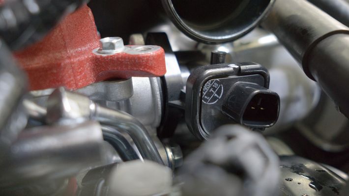
- Remove the TGV electrical harness.
- Remove the (2) 10mm bolts holding the TGV to the manifold.
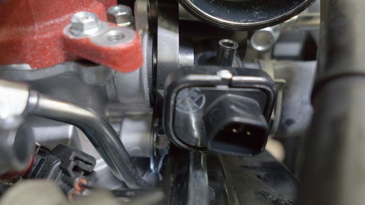
Gently and carefully remove the TGV from the manifold.
BE CAREFUL TO VERIFY THE POSITION OF THE GEARS AND DO NOT DAMAGE THE O-RING. It helps to take a picture in order to verify its orientation. or mark it using a marker. This needs to be back in the original orientation when you go to put it back together.
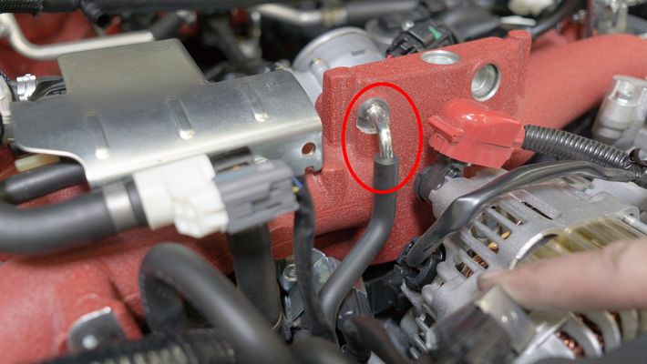
- Remove the 12mm bolt holding the fuel line to the manifold.
- Remove the (2) 12mm bolts holding the fuel rail on the passenger side.
- Remove the (2) 12mm bolts holding the fuel rail on the driver's side.
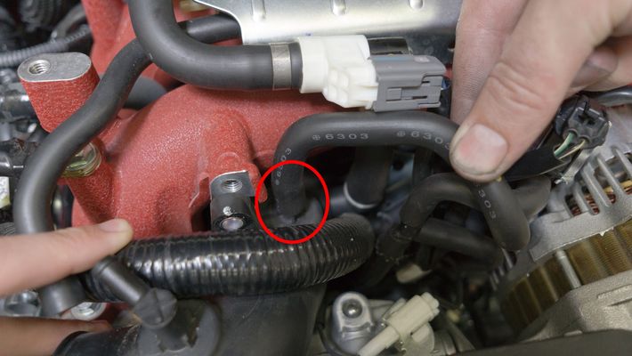
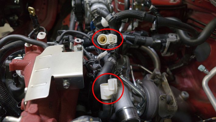
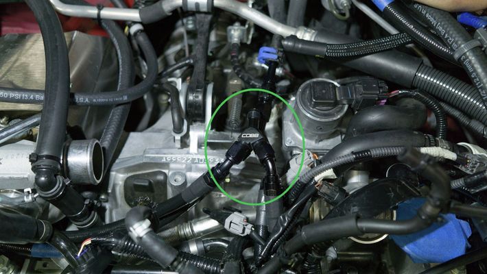
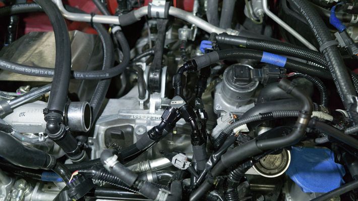
- Disconnect the (2) PCV hoses
- Remove the (6) 10mm bolts securing the intake manifold on the passenger's side.
Remove the (6) 10mm bolts securing the intake manifold on the driver's side
After the bolts are loose, you can use a magnet to remove them easier.
Gently lift the fuel rail, pushing down on the injectors to keep them seated. You cannot completely remove the intake manifold yet. This step is for gaining clearance to the underside, so do not force it.
A small amount of fuel will spill, so it's a good idea to have a rag handy to catch it.
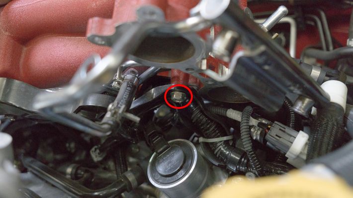
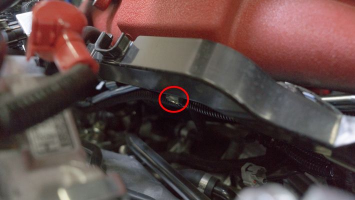
- After you've lifted the intake manifold slightly, there will be (2) 12mm bolts underneath that you need to remove. (1) is on the underside-middle, the other is on the underside-driver.
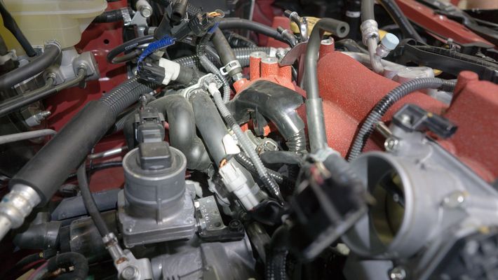
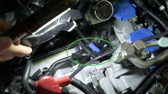
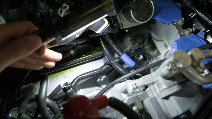
- Disconnect the vacuum line from the passenger side of the intake manifold.
- There is one remaining vacuum line that you will need to remove near the backside of the intake manifold.
Gently remove the intake manifold. Be cautious of the TGV gears and the (2) intake manifold gaskets.NOTE: You may need to move the wiring harnesses around to allow clearance for the intake manifold.
Once removed, we recommend covering the exposed ports to prevent foreign material contamination.
Removal of the OEM Fuel Rails and Lines
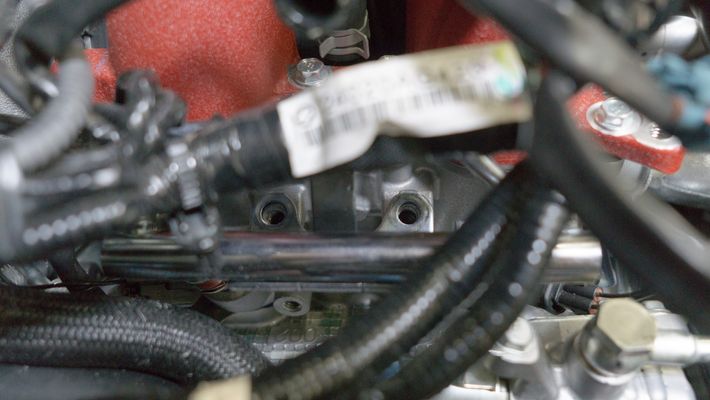
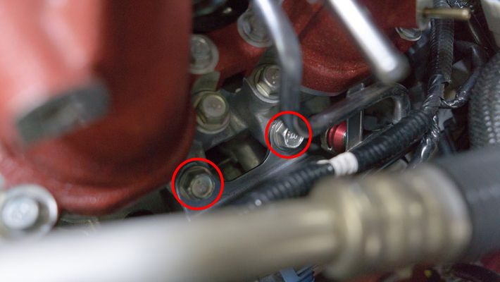
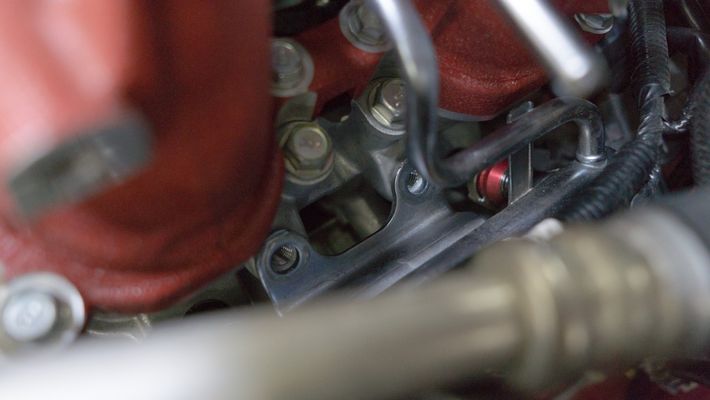
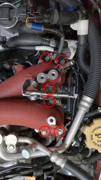
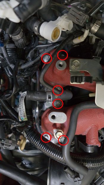
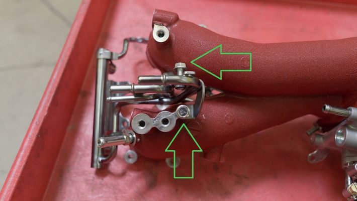
- Remove the (2) 10mm bolts securing the upper side of the driver's side fuel lines and rail assembly.
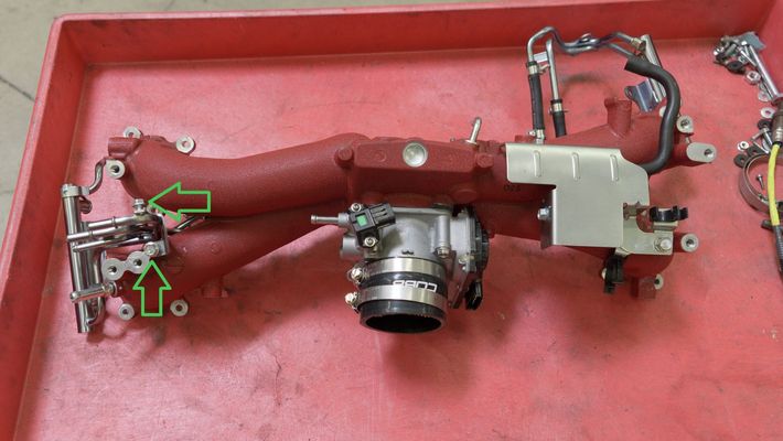
- Remove the (2) 10mm bolts securing the lower side of the driver's side fuel lines and rail assembly.
- Remove the injectors by gently pulling outward.
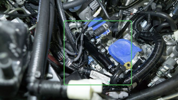
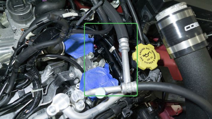
2018-2021 STI FPR Assembly Removal
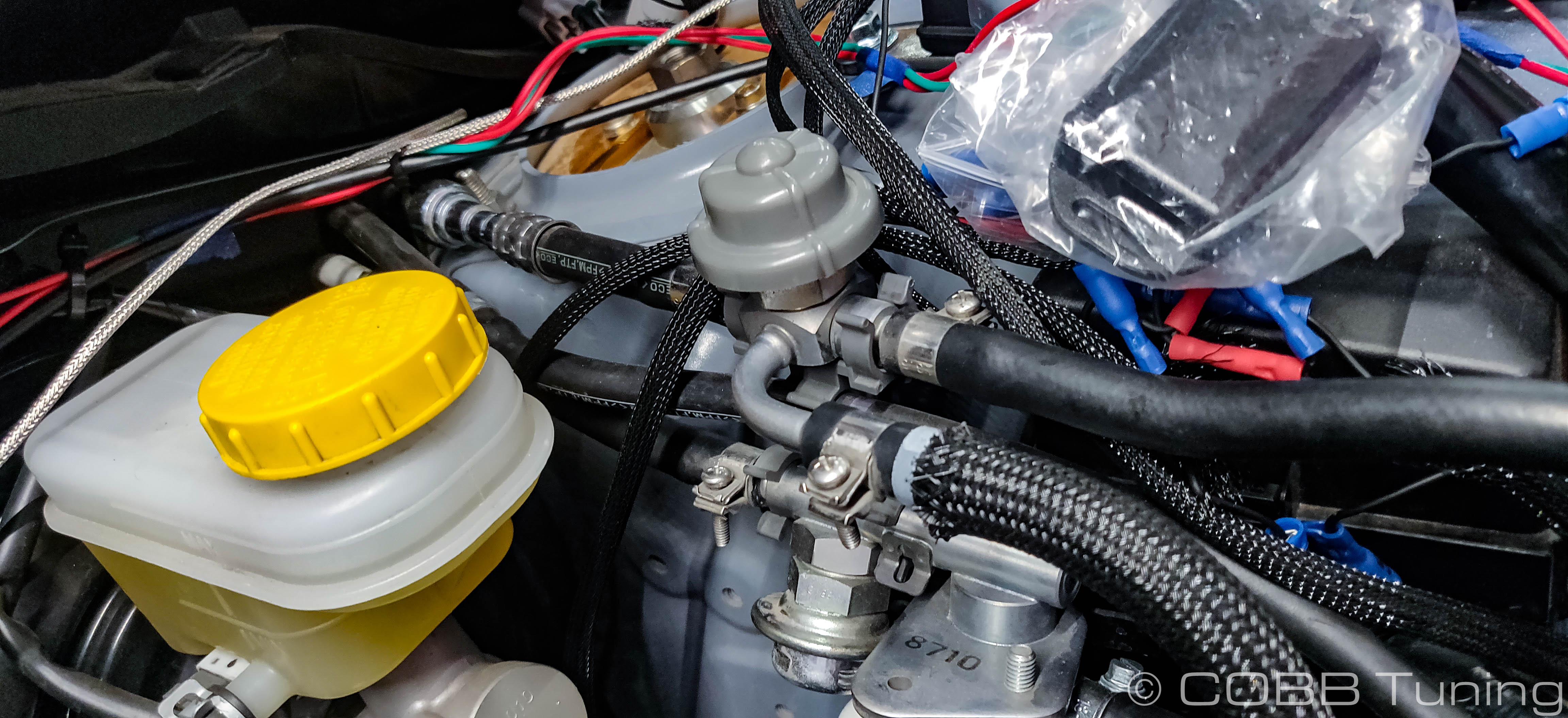
- When disconnecting the feed and return lines from the firewall you'll noticed the factory fuel lines are a bit more complicated than previous yeras with a regulator and damper built into the middle. This entire assembly will be removed and replaced.
Installation of the COBB Fuel Rails
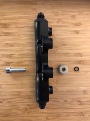
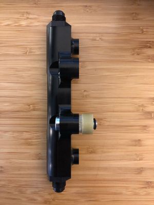
Assemble the provided ID1050x injectors, injector spacers (0.625", larger sized version for the ID1050x injectors), injector pigtails, socket head bolts, and o-rings onto the fuel rails.

- Assemble the rails as such (bolt, rail, spacer, o-ring):
 .
.  .
. 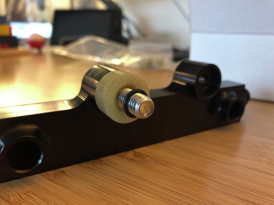
- Assemble the rails as such (bolt, rail, spacer, o-ring):
Gently place the assembled driver and passenger side fuel rails on the motor. Once oriented, you'll give a gentle push to fully seat the injectors.
FPR Installation
Installation of the COBB Fuel Lines
With your rails seated, it's now time to install the fuel lines. Each line is labeled according to it's position in the fuel line system. The line label is on the side which connects to the fuel rail. If you are connecting to the ethanol sensor and using Line 6, you will require https://www.cobbtuning.com/products/fuel-system/subaru-fuel-rail-line-kit-to-flex-fuel-sti-2008-2019/. Line 6 is not included in the standard Rail/Line package. Please verify you have that line, if needed, prior to beginning installation. 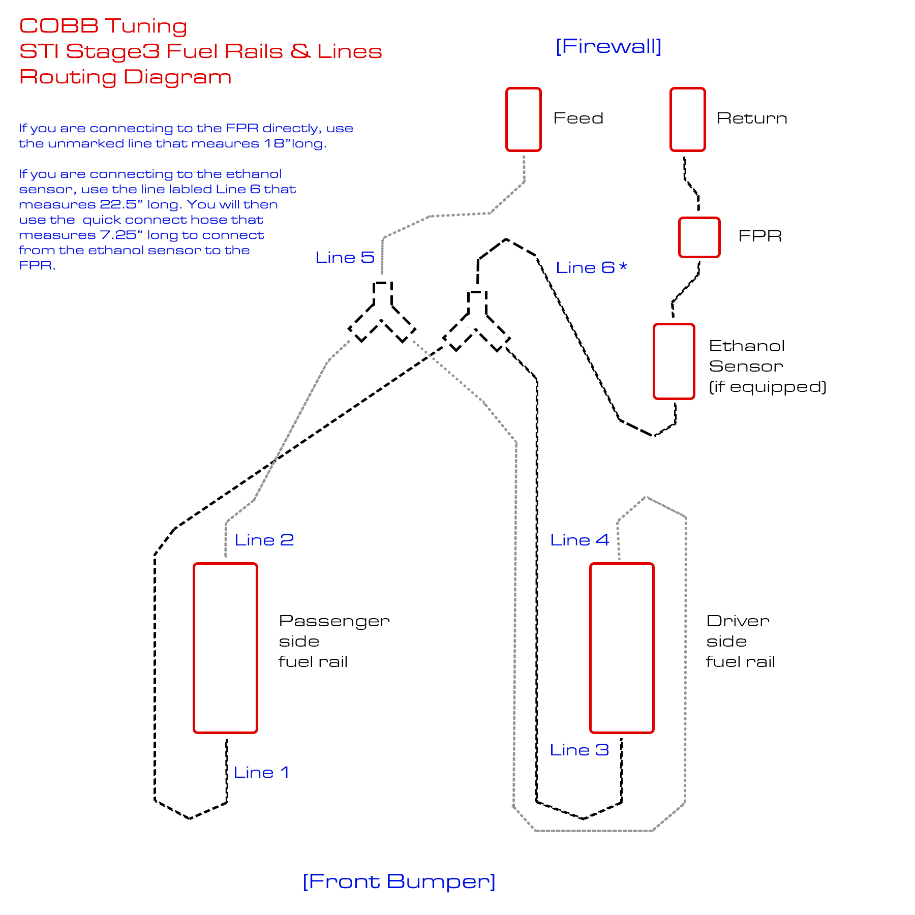
- Each fuel line has a 3" bend radius Please do not bend or kink these fuel lines beyond that amount in order to prevent damage.
- Torque Specs for the AN lines are 12-16 ft/lbs
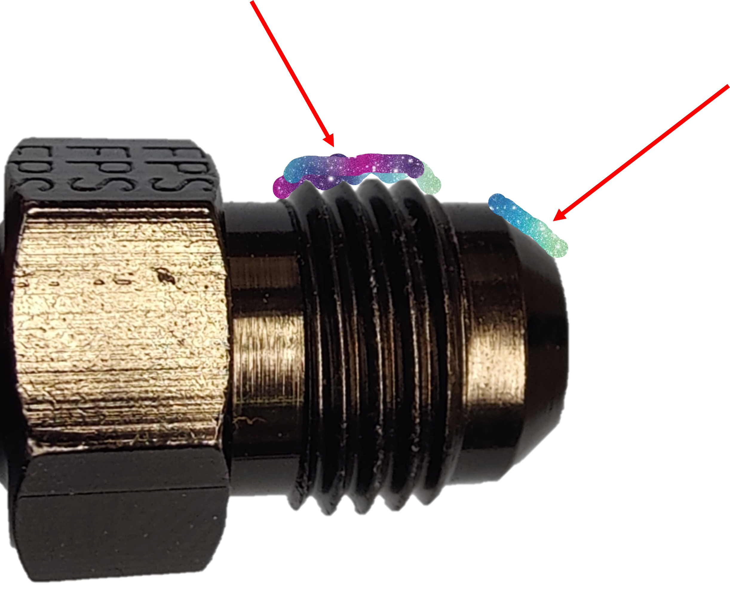
- Please apply either the provided silicone lubricant on the AN fitting threads and the face of the male ends to prevent seizing.
- Begin by installing the 90 degree fitting of Line 2 on the firewall facing passenger side fuel rail. Route the fuel line under the turbo inlet and under the PCV hoses.
- Install the 180 degree fitting of Line 1 on the front facing passenger side fuel rail. Route the fuel line along the rail to follow the path of Line 2, under the turbo inlet and under the PCV hoses.
- Install the 90 degree fitting of Line 3 on the front facing driver side fuel rail. Route the fuel line under the a/c compressor hard lines and under the wiring harnesses.
- Install the 180 degree fitting of Line 4 on the firewall facing driver side fuel rail. Route the fuel line along the rail toward the front of the rail, following the same path as Line 4, under the a/c compressor hard lines and under the wiring harnesses.
- We recommend zip tying the two fuel lines running from the driver side fuel rail together near the engine wiring harness.
- With the fuel lines connected to each rail, we will now install a Y-block to each pair to route the lines to the appropriate fuel feed or fuel return line.
- Connect Line 1 and Line 3 to a provided Y-block. These lines will converge into the return fuel line.
- Connect Line 2 and 4 to a provided Y-block. These lines will converge into the feed fuel line.
- Install the provided female-female adapter and 3/8" FI line adapter.


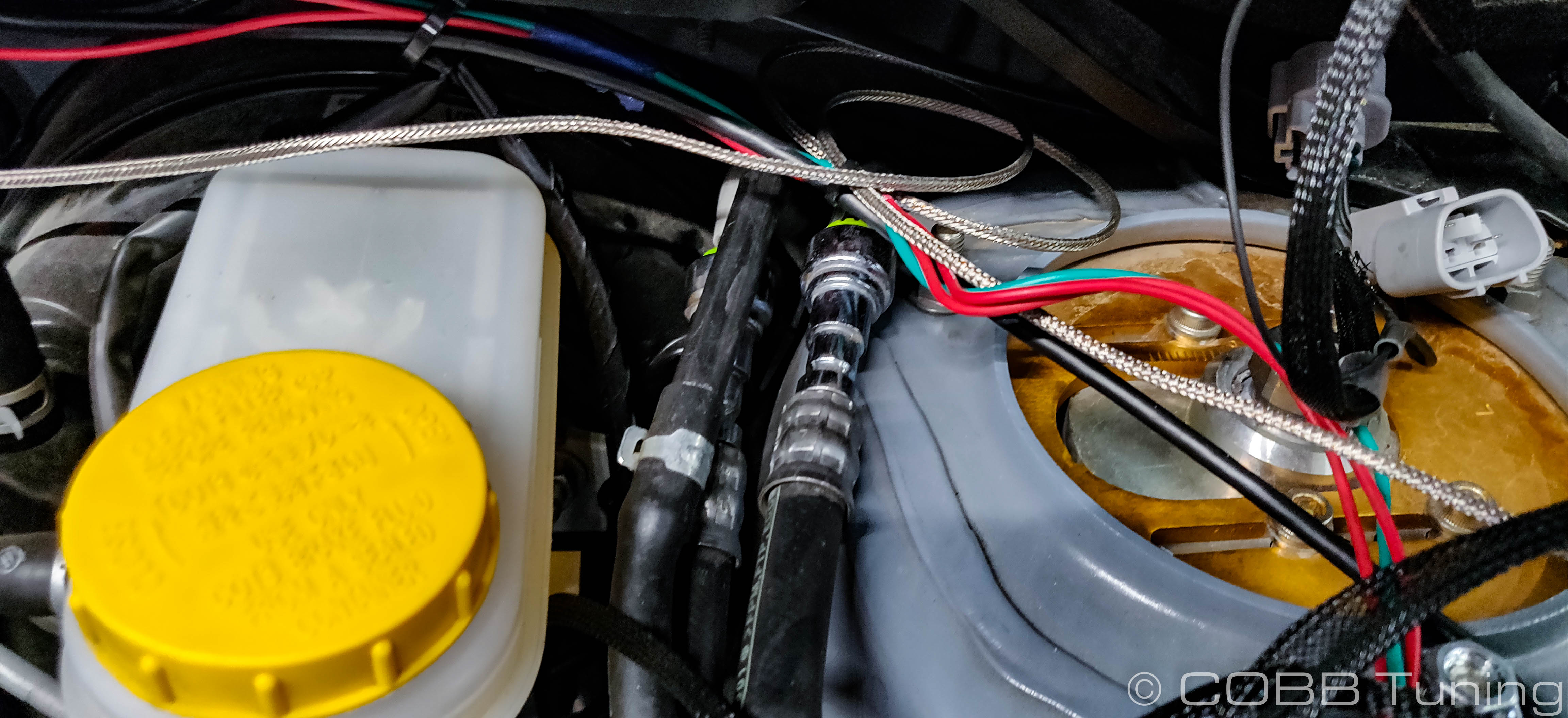
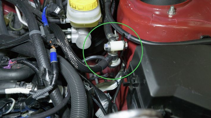
- Using the provided 18" long unmarked line, connect the 90 degree fitting to the fuel line quick connect. Fit the opposite end to the FPR and secure it using the provided hose clamp.
- Install the provided female-female adapter and 3/8" FI line adapter.
- Install the quick connect adapter to the feed hard line coming from the firewall using a silicone lubricant, such as SuperLube (included), to avoid damaging the O-ring.
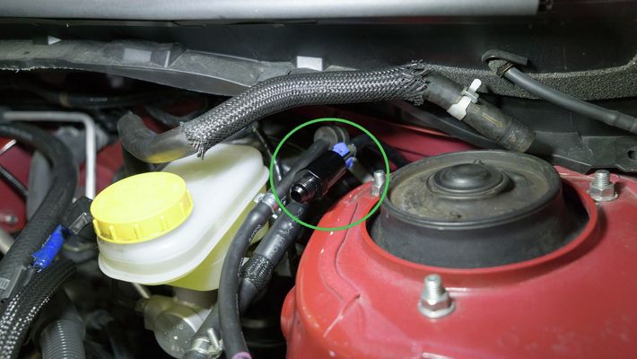
- Connect the 30 degree fitting on Line 5 to the feed hard line adapter.
- Connect the 30 degree fitting on Line 5 to the Y-block for Line 2 and Line 4.
- With the lines now installed, we recommend connecting the battery, priming the fuel pump, and checking for any leaks. DO NOT START THE VEHICLE OR SERIOUS DAMAGE MAY OCCUR.
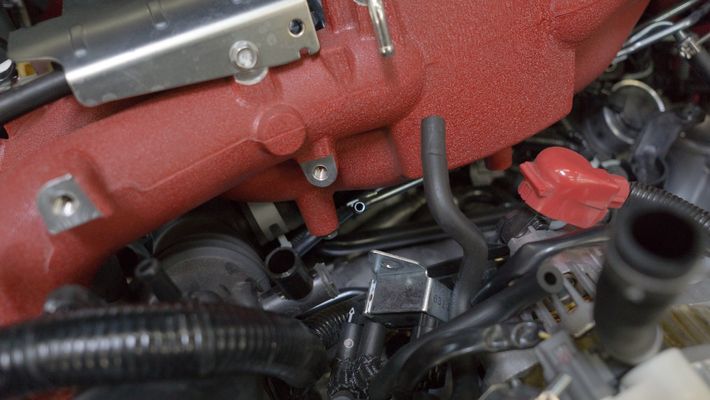
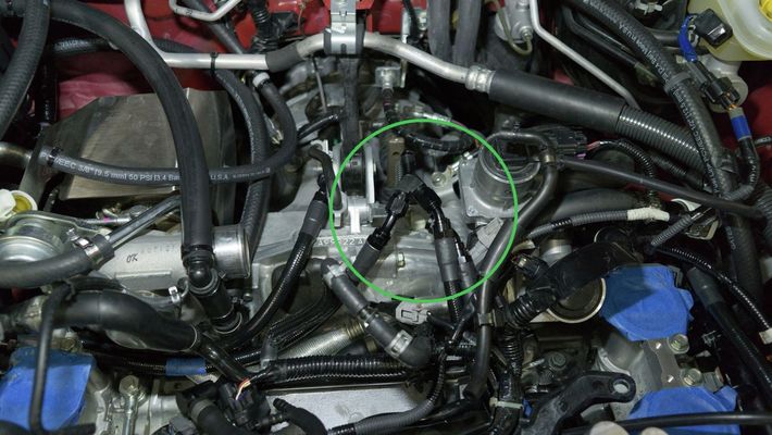
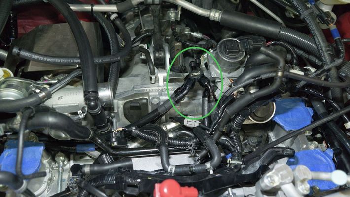
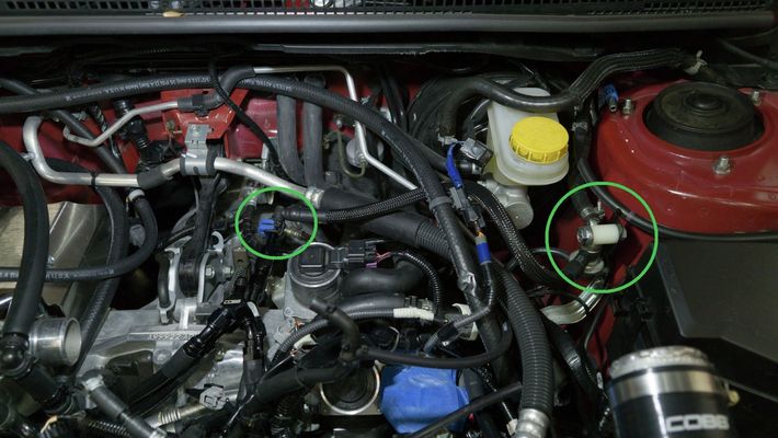
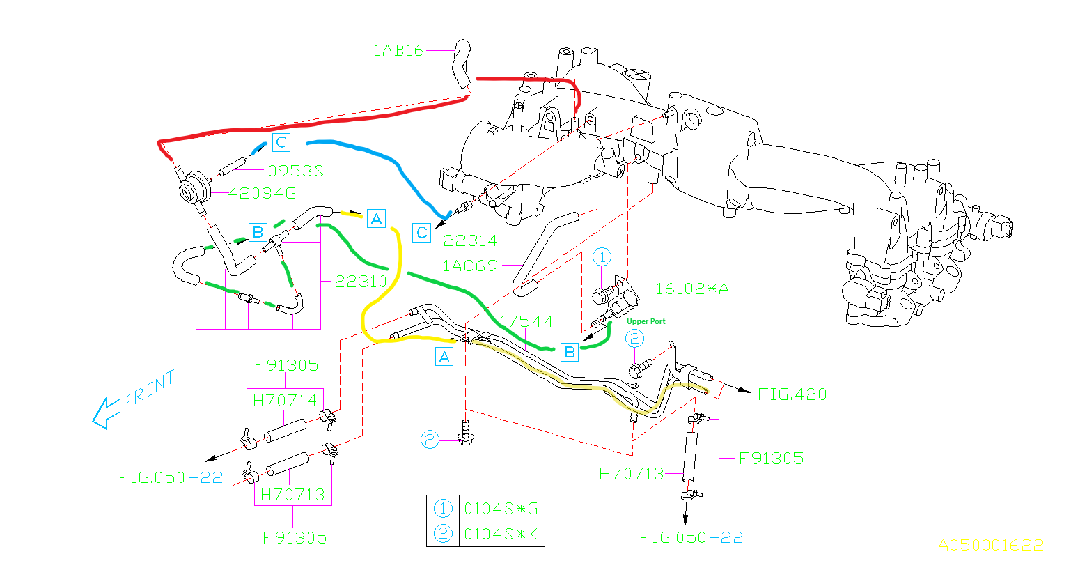
- If there are no leaks you'll proceed to replacing the EVAP line. This is the remaining line coming from the firewall that used to go to the third metal line on the intake manifold to the assembly of vacuum tees and valves near the inlet. To replace you'll attach the provided vacuum line to the third, non-quick-connect port on the firewall and run it over to where the old line used to attach to the twisty evap valve assembly. The below diagram should give you a better idea of the factory routing paths
Reinstall the Intake Manifold
- Proceed in reverse to reinstall the intake manifold. Be wary of the engine wiring harness, vacuum hoses, and fuel lines.
- Relocate the manifold refernce vacuum for the fuel pressure regulator as shown here Manifold Reference Relocation
- Once completed, we recommend conducting a pressurized smoke test to verify there are no intake/boost leaks.
Final Notes
- Flash the appropriate map to the ECU for the installed components PRIOR to cranking or driving the vehicle.
- Please contact COBB Support at 866.922.3059 or at Support@COBBTuning.com if you have any questions along the way!
Links
COBB Product Install Instructions for Subaru Vehicles
Main Installation Instruction Repository for Subaru Parts
Calibration Map Notes for Subaru Vehicles
Link to Subaru Map Notes to see what map you should be on given the parts you've added
Contact Us:
COBB Customer Support
Web Support and Tech Articles: COBB Tuning Customer Support Center
Email: support@cobbtuning.com
Phone support available 9am to 6pm Monday-Thursday. 9am to 4pm Friday (CST)
866.922.3059
return to www.cobbtuning.com
Copyright 2025 © COBB Tuning Products LLC. All Rights Reserved. | www.cobbtuning.com