712500-SL or 712500-BK - Subaru Front Mount Intercooler Kit WRX or STI 2004-2007

712500-SL, 712500-BK
Subaru Front Mount Intercooler Kit WRX/STI 2004-2007
Congratulations on your purchase of the Subaru Front Mount Intercooler Kit STI 2004-2007. The following instructions will assist you through your installation process. Please read them first entirely BEFORE beginning the install and familiarize yourself with the steps and tools needed. If you feel that you cannot properly perform this installation, we HIGHLY recommend you take the vehicle to a qualified and experienced automotive technician.
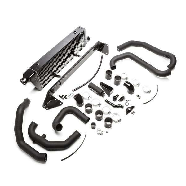
Part List
Intercooler Core Assembly
- Intercooler Core
- Bumper Beam
- M6x25 Flange Head Bolt
- 2ft 1/2" Silicone Vacuum Hose
- 1/2"x1/2"x1/2" HDPE Black Tee
- 1/2"x1/2" HDPE Black Elbow
- COBB Stencil
Overflow Tank/ Washer Fill Relocation
- Overflow Tank
- Overflow Tank Mounting Bracket
- Silicone Washer Fill Hose
- Washer Fill Hose Clamp
- Washer Fill Hose Tank Adapter
- -124 O-ring
- M6x12 Button Head Hex Screws
- Washer Fill Cap
Hot Side Piping
- Upper Hot Pipe
- Lower Hot Pipe
- 1 x Silicone Reducer Elbow 2.0" x 2.5"
- 2 x 2.5" Straight Silicone Coupler
- 1 x Rubber Isolator
- 2 x M6 Flange Nut - Rotating
- 5 x #44 Clamp
- 1 x #36 Clamp
- Edge Trim - 1 ft
Cold Side Piping
- Upper Cold Pipe
- Mid Cold Pipe
- Lower Cold Pipe
- 1 x Silicone Reducer 2.75" X 2.5"
- 2 x Silicone Straight Coupler 2.5"
- 1 x Silicone 45° Elbow 2.5"
- 1 x BPV Silicone Coupler
- 1 x 3/8" NPT Plug
- 1 x #48 Clamp
- 7 x #44 Clamp
- 2 x #20 Clamp
Tools Needed
- 7mm Socket
- 8mm Socket
- 10mm Socket
- 12mm Socket
- 14mm Socket
- 3/8" Drive Ratchet
- Various length 3/8" Extensions
- Pliers
- Flat Blade Screwdriver
- Phillips Screwdriver
- Plastic Clip removal Tool
- Air Saw, rotary cutting tool, or utility knife
Parts Required for Install
- Cobb SF Intake
Parts Recommended for Install
- Cobb Airbox
- Cobb Bypass Valve
Removal of Battery / Intake / Intercooler
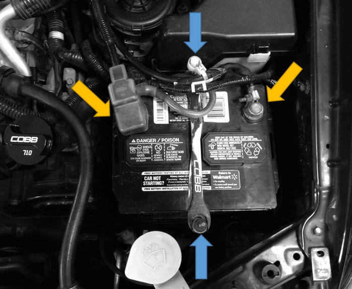
- Using a 10MM socket or wrench, disconnect the battery (yellow arrows). Then loosen the J-hooks and remove the battery and battery tray (blue arrows).
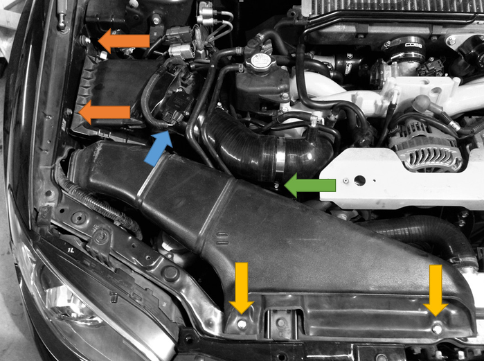
- In order to remove the stock intake system, first remove the stock snorkel by removing the two bolts on the core support using a 10MM socket (yellow arrows.) Next, un-clip the MAF sensor connector (blue arrow). Finally, loosen the clamp on the intake tube (green arrow) and unbolt the air filter housing from the passenger side fender well (orange arrows.) Remove the assembly from the car.
- To remove the stock/aftermarket bypass valve, disconnect the vacuum line from the top of the valve (green arrow) and remove the pinch clamp from the nose (blue arrow). Then unbolt the valve using a 12MM Socket or wrench (yellow arrows). Remove the valve from the car.
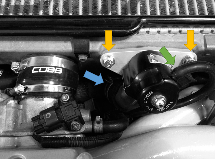
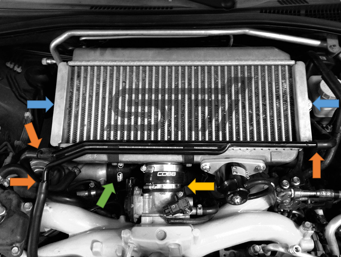
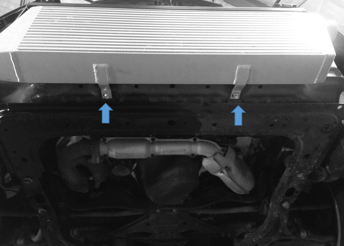
- In order to remove the top mount intercooler, first loosen the clamp holding the intercooler to the throttle body (yellow arrow.) Then loosen the clamp on the turbo inlet (green arrow.) Next gently remove the PVC lines from the hard line attached to the intercooler core (orange lines) Using a 12MM socket, remove the bolts holding the intercooler core to the mounting brackets (Blue arrows.) Removal of the stock intercooler mounting brackets as well.
Removal of the Front Bumper Cover and Bumper Beam
- Raise the car up using on a lift or floor jack and jack stands to gain access to the underside of the car.
- Remove the 6 clips holding the bumber to the fender liners.
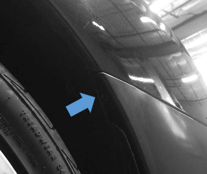
- Now remove the two screws attaching the bumper to the fender near each wheel well. There will be one on each side.
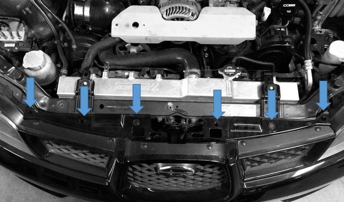
- Now remove the six push pins holding the top of the bumper to the center of the core support.
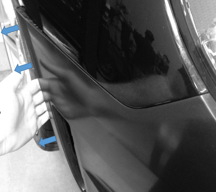
- At this point the bumper should be free from the car. Gently pull outward from each side of the car near where the fender and bumper meet. Continue to pull and gently lift until the bumper had completely detached from the fender. TIP: It may be helpful to have an extra set of hands at this point to reduce the risk of scratching the bumper cover and/or bending the mounting clips.
Removal / Installation of Coolant Tank and Windshield Washer Reservoir
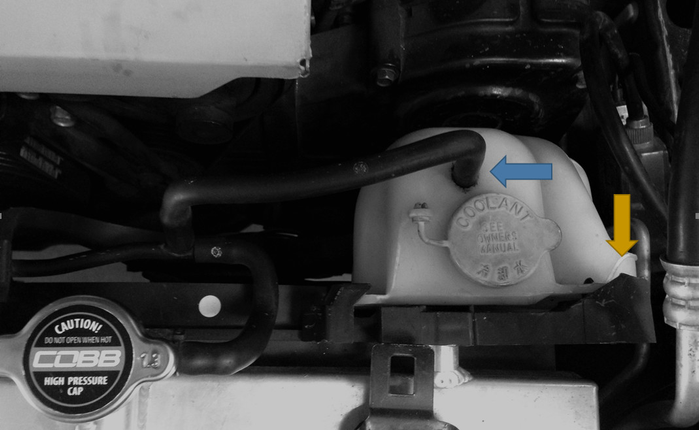
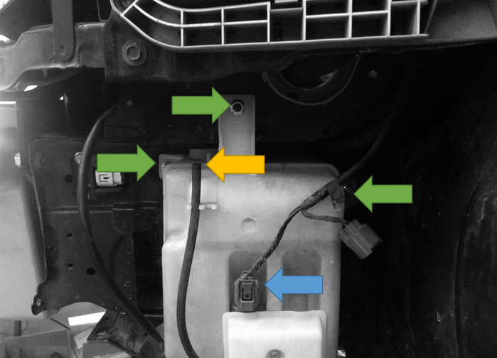
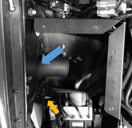
- To remove the coolant reservoir, first remove the rubber hose running into the top of the reservoir itself (blue arrow.) Then press the clip on the right side of the reservoir (yellow arrow) and pull straight up to remove it.
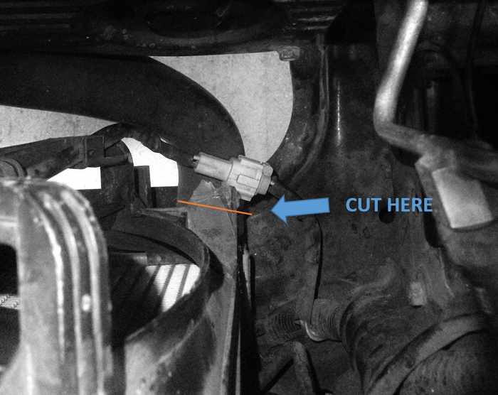
- The driver's side of the radiator fan shroud will need to be trimmed to make room for the cold side piping. Mark and cut along the orange line using an air saw or rotary tool.
FOR 2006-2007 YEAR MODELS ONLY (For 2004-2005 year models, skip to step 8) - If the vehicle is a 2006-2007 model, the washer fluid reservoir needs to be removed. Remove the push pin holding the washer fill hose from the core support near the driver's side headlight.
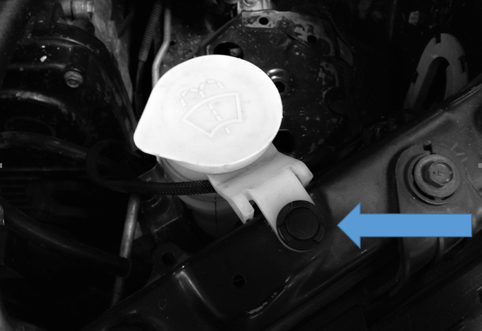
- Unplug the washer pump harness (blue arrow) and disconnect the washer line at the elbow (yellow arrow.) Then using a 10MM socket with an extension remove the two nuts and bolt that attach the washer tank to the car (green arrow.) The assembly including the neck should come out from the bottom of the car.
 '
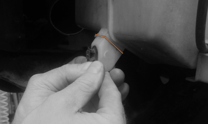
' - The washer fluid reservoir will need to be modified to clear the cold side piping. Using an air saw or rotary tool, mark and cut along the orange line to remove the tab.
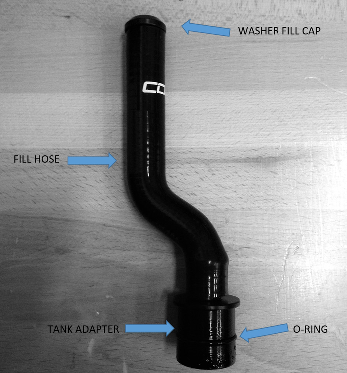
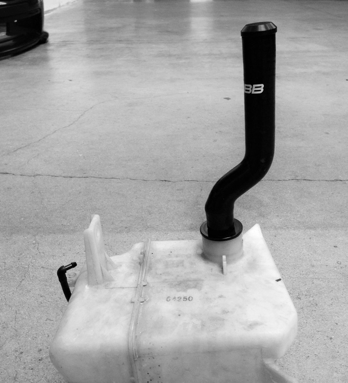
- With the washer bottle out of the car, remove the factory fill neck by pressing in the tab wish a screwdriver and pulling upward. Then install the new hose assembly into the washer tank with the hose pointing toward the side that mounts to the car.
- With the new hose assembly in place, bolt the reservoir back in the car and reconnect the washer line and washer pump wiring.
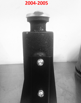
- Install the coolant mounting bracket onto the driver's side frame rail. Tighten the M6 Flange head bolt using a 10MM Socket.
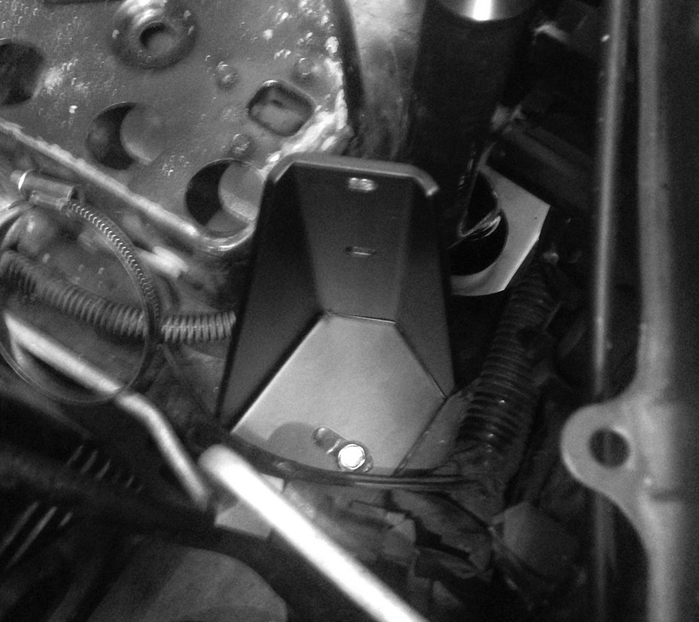
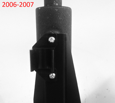
- Now install the new coolant overflow reservoir. Fasten the assembly together using M6x12 button head screws. Tighten using the supplied 4MM hex key. If the car is a 2006-2007 year model, also install the washer hose clamp. Then clamp the hose in the bracket.
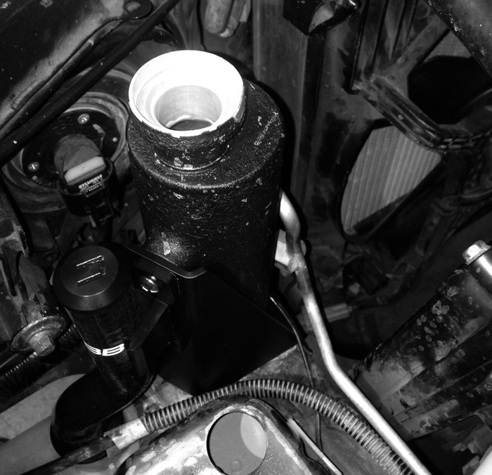
- The finished should look like this in the car.
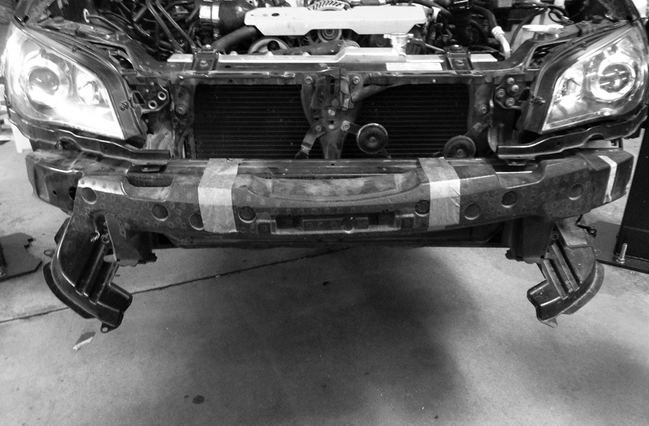
Removal / Installation of Bumper Beam and Intercooler Core
The original bumper beam needs to be replaced with the Cobb bumper beam to allow room for the new intercooler core.
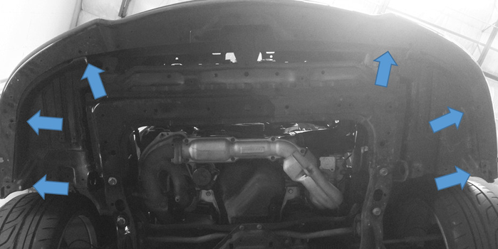
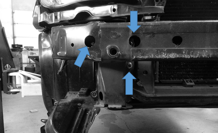
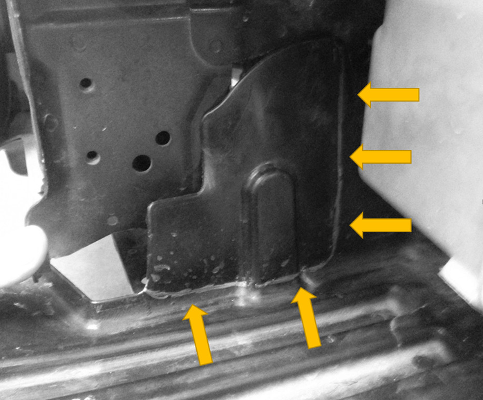
- First remove the foam bumper from the front of the bumper beam. Then, using a 14MM socket with an extension, loosen the 4 nuts and 2 bolts holding the bumper beam to the car. There will be 1 bolt and 2 nuts per side (blue arrows.)
- Next, bolt the Cobb bumper beam in place re-using the factory hardware.
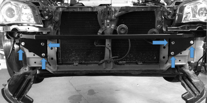
- Now carefully trim some components to provide clearance for the intercooler core. When looking down at the core support from the front of the car there are two tabs that stick out further than the rest. These will either need to be bent up or cut off to provide clearance for the core. Either method is acceptable. Check for clearance by holding up a straight edge along with the bottom of the core support to ensure that these two tabs do not stick out further than the rest of the ridges. Cut along the orange dotted line shown below.
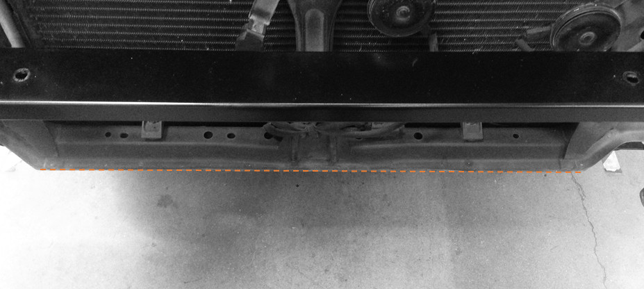
- With the bumper beam installed, hold the intercooler in position against the beam. The mounting posts of the intercooler should align with the holes in the bottom side of the bumper beam. With the bumper beam in place, loosely install the two M8x25 flange head bolts through the beam into the mounting posts of the core. Then from the bottom of the car install the two bolts that attach the lower intercooler brackets to the core support. Once the intercooler is aligned all four bolts can be tightened.

Installation of Hot Side Piping
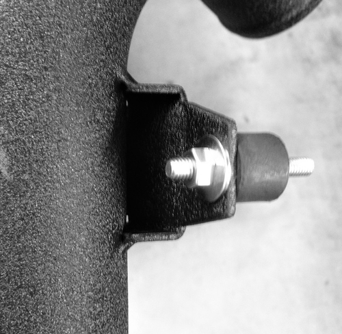
- In order to install the lower hot side pipe fasten the rubber isolator to the bracket on the lower hot side pipe with the 6MM flange nut. Hand tighten to allow for adjustment.
- Slip a 2.5" silicone straight coupler over the straight end of the pipe along with 2 clamps that will attach to the intercooler.
Feed the bent end of the hot side pipe up though the fender into the hole where the factory intake once was (blue arrow.) The rubber isolator will align with a small hole in the fender between the two intake holes in the fender. Hand tighten the other 6MM flange nut on the stud that comes though the fender (yellow arrow.)
In order to properly fit the COBB FMIC, the COBB SF Airbox (if installed) must be trimmed. Please print the following attachment in full size and in landscape mode. At that point, you can tape the template on the SF airbox and proceed to trim along the designated sections.
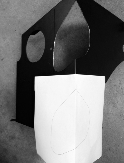
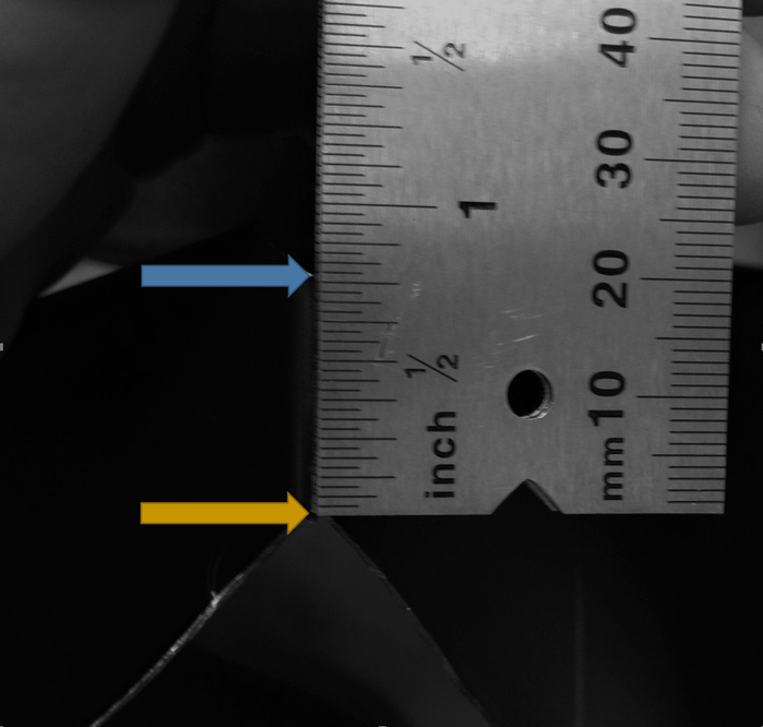
If using a Cobb air box, print out the PDF attached below and use the template to cut the air box to allow the upper hot side pipe to pass though. The template should lay on the box like the picture below. the top of the template (once cut from the sheet) should be 3/4" from the top of the corner (blue arrow) of the box. Once the outline of the template is traced onto the air box, use an air saw or rotary tool to cut along the guideline to make room for the upper hot pipe. Once cut, cover the cut edge of the air box with the supplied edge trim.
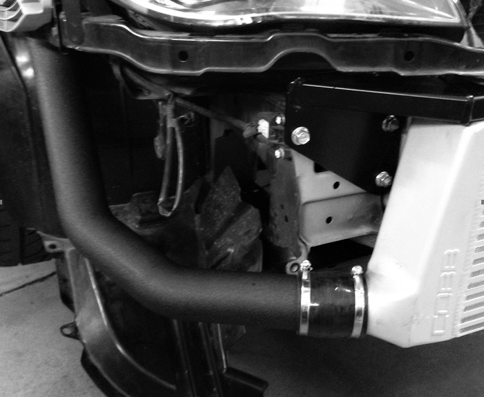
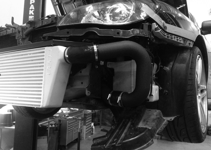
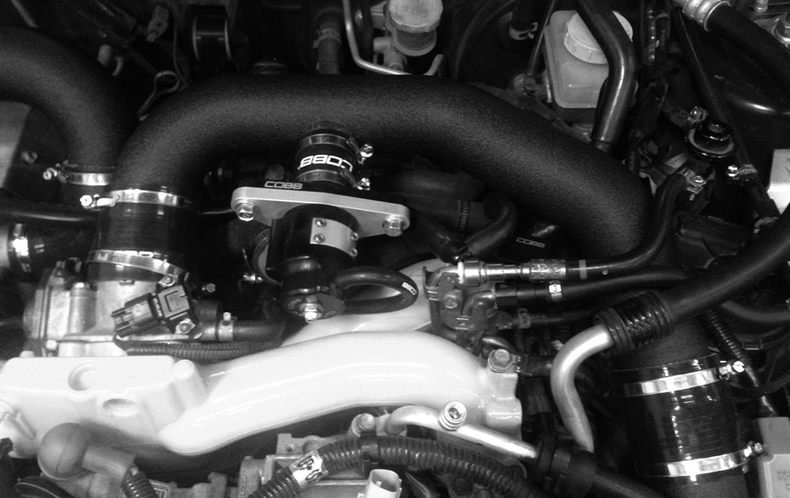
- Now place a 2.5" straight silicone coupler and two clamps over end of the lower hot pipe coming though the fender. Place the 2.0" to 2.5" silicone 90° over the turbo end of the upper hot pipe. Route the pipe though the air box (if equipped) and connect the two hot pipes together and the upper hot pipe to the turbo outlet. The final hot pipe assembly should look like this.
- Once all the final adjustments are made, tighten all the clamps as well as the vibration isolator.
Installation of Cold Side Piping
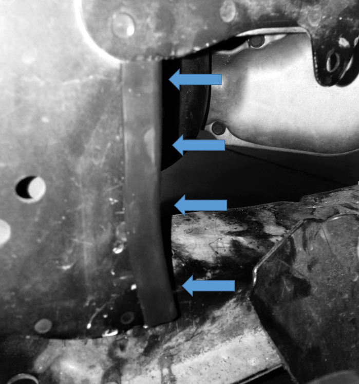
- The lower fender liner on the drivers side needs to be trimmed to accommodate the lower cold side pipe. Use the picture below as a guide as to where to mark the fender liner to trim. Once marked, cut the fender liner with an air saw or rotary tool.
- Add a piece of supplied edge trim to the pinch weld near the core support to protect the lower cold pipe.
- Slide a 2.5" straight silicone coupler along with 2 clamps over the outlet end of the lower cold side pipe. Next, slide the 45° 2.5" silicone coupler along with 2 clamps over the outlet of the intercooler. Now, slide the lower intercooler pipe into the 45° silicone coupler on the intercooler.
- Next, Slide a 2.5" straight silicone coupler over the upper outlet of the middle cold pipe. From the top of the car, install the middle cold pipe staying to the right of the A/C line. Slip the inlet of the middle cold pipe into the 2.5" straight silicone coupler on the outlet of the lower cold pipe.
- Install the 3/8" NPT plug (if needed) into the bung on the back of the upper cold pipe.
- Now slide the 2.75" - 2.5" reducer over the throttle body. Slide the bypass valve silicone coupler over the bypass valve outlet on the upper cold pipe. Insert the upper cold pipe outlet into the silicone reducer on the throttle body and the upper cold pipe inlet into the 2.5" straight silicone coupler on the outlet of the middle cold pipe. Lightly clamp all the silicone couplers to allow for adjustment.
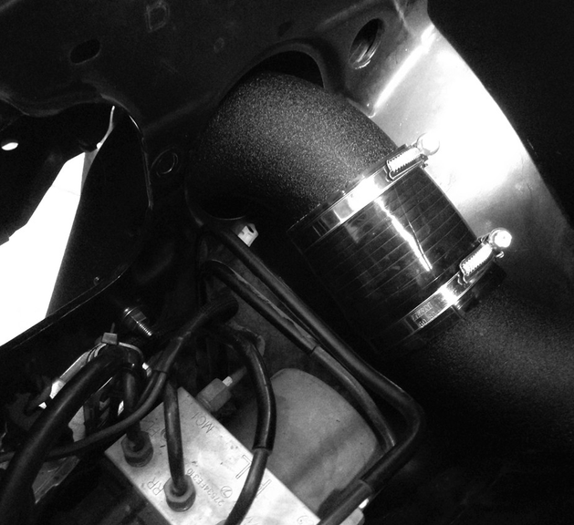
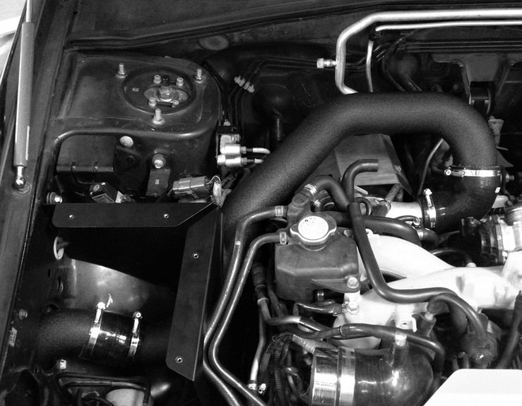
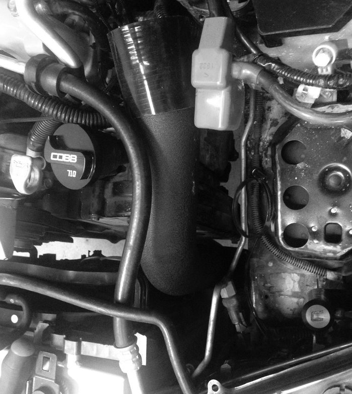
- Install the BPV adapter (if needed) and re-connect the BPV to the BPV outlet hose and vacuum source. Check for clearances and tighten down all of the cold side piping. The cold side piping should like like the pictures below.
Trimming the Bumper Cover
With all the new intercooler components in place, it's time to clearance the bumper cover to fit over the new front mounted core. These instructions are a general guideline as every install will be slightly different. There are a variety of tools one can use to accomplish this task, choose the one that you feel most comfortable with. The following steps are a quick overview of what trimming needs to take place. Go slowly. Be conservative. It's a lot easier to remove a little more than add material back in.
- If desired, use the provided template to paint "COBB" onto the front of your core as seen below. Make sure to mask off the surrounding areas around the template to prevent any over-spray.
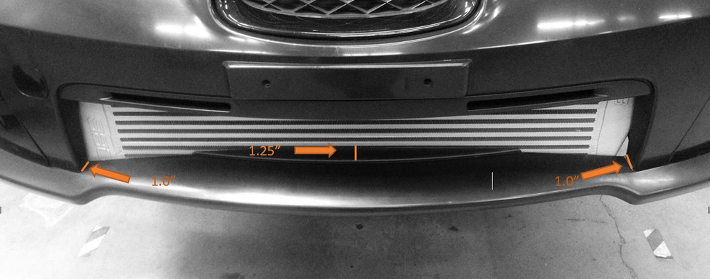
- Start by marking the bottom of the bumper opening in each corner and the center. From the edge shown by the orange arrows, measure inward 1.0" from each corner. Now measure 1.25" from the center to the edge of the small lip.
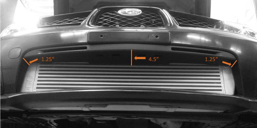
- Now mark the top of the bumper opening in each corner and the center as well. Measure 1.25" from each corner and 4.5" from the center.
- Now mark/draw/tape a line intersecting all three points on both the top and bottom.
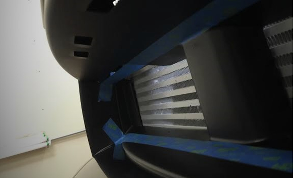
- After double checking all measurements, use the method most comfortable (air saw, utility knife, cutoff wheel, etc.) to you to cut the bumper along the cut line.
TIP: Its much easier to cut less than the desired amount and work your way out than cutting too much the first time. - Once the bumper is cut, loosely install it into place, making sure that you've removed enough material for everything to fit nicely.
- Once the bumper cover has proper clearance, it's time to reinstall everything in the order it was removed. Make sure to double check fitment of all components as well as making sure everything is properly torqued. Also, double check that all hose clamps are tight and secure.
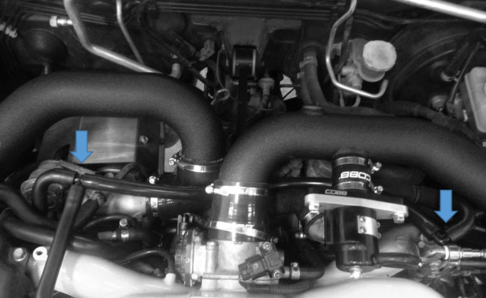
Installing PVC hose / Intake System
- Connect the two PCV lines on the passenger side of the engine bay with the 1/2" Tee. Now slide the 1/2" Elbow into the PCV line of the drivers side. Connect the barbs with the supplied 1/2" silicone hose.
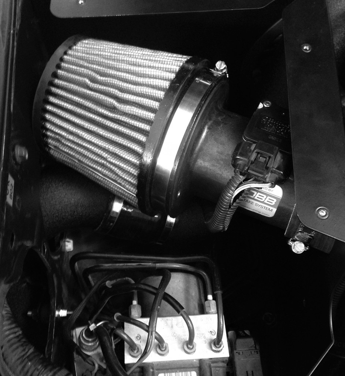
- Install the intake system as normal. The bracket connecting the MAF housing to the car will not be used.
- Once everything is back installed, make sure you're running a proper ECU calibration for your new piece of hardware and get out there and enjoy the fresh, cooler intake temps provided by your COBB FMIC!
Links
COBB Product Install Instructions for Subaru Vehicles
Main Installation Instruction Repository for Subaru Parts
Calibration Map Notes for Subaru Vehicles
Link to Subaru Map Notes to see what map you should be on given the parts you've added
Contact Us:
COBB Customer Support
Web Support and Tech Articles: COBB Tuning Customer Support Center
Email: support@cobbtuning.com
Phone support available 9am to 6pm Monday-Thursday. 9am to 4pm Friday (CST)
866.922.3059
return to www.cobbtuning.com
Copyright 2024 © COBB Tuning Products LLC. All Rights Reserved. | www.cobbtuning.com