315250 - COBB Fuel Pressure Regulator Kit
- Chris Mitchell (Deactivated)
- Brandyn Mowat
- Former user (Deleted)

315250
COBB Tuning Fuel Pressure Regulator Kit Install Instructions
Subaru WRX STi 2008 - 2021
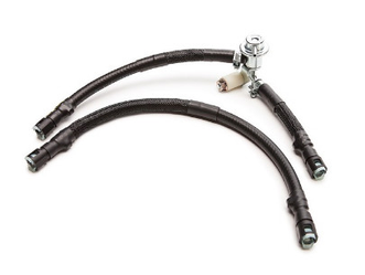
Part List
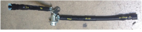
- 1 x Fuel Pressure Regulator
- 1 x Long Assembled Fuel Line (Feed/Upper Line)
- 1 x Medium Assembled Fuel Line (Return/Lower Line)
- 1 x Small Assembled Fuel Line (Return/Lower Line)
- 1 x Spacer
- 1 x M8x35 Flange bolt
- 1 x M8 Flange nut
- 2 x Fuel Injection Hose Clamps
- 6 x Small Zip Ties
- 1 x Manifold Reference Relocation "Tee"
- 1 x Small Black Vacuum Cap
- 1 x Section of 6mm black silicone hose (Tee to FPR line)
- 1 x Section of 4mm black silicone hose (Tee to BPV line)
Tools Needed
- 5/16" or 8mm Fuel Line Disconnect Tool (Available at Professional Tool Sources)
- 7mm Nut Driver
- Flat Head Screw Driver
- 10mm Wrench
- 12mm Wrench
- 10mm Socket
- 12mm Socket
- Ratchet
- Pliers
- Diagonal Cutters or Scissors (Hose Cutting tools suggested for straight cuts)
- Safety Glasses
- Rags
- Silicone Spray or Similar
Important! Before removing your fuel line, make sure to discharge existing fuel pressure from the system. Failure to do so can result in fire and burns!
Removal of Stock Fuel Lines
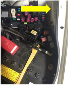
- If possible, discharge the existing fuel pressure from the system. One potential method is to disable the fuel pump by pulling the fuse on the driver’s side of the engine bay (consult the underside of the lid for correct fuse location), then attempt to start the vehicle. Consult the factory service manual for OEM methods.
- Disconnect the vehicle’s negative battery terminal with a 10mm wrench or socket. Ensure no alternate sources of spark or flame are present.
- Prepare spill catch rags in case of fuel spills during OEM line removal.
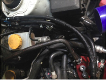
- Remove the factory fuel lines and fuel pressure regulator (FPR) from the fuel rails and feed/return lines using 5/16" or 8mm quick-disconnect fuel line tool (I.E. AST #8028). Removal can be tricky, so please take your time.
When done properly, the connectors will easily slide off.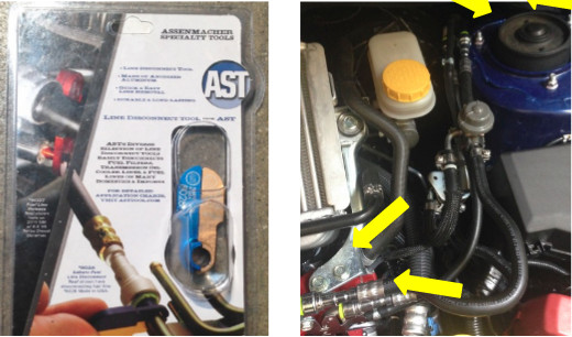
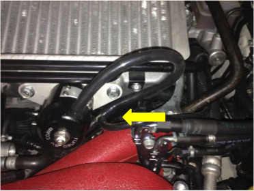
- Remove the fuel line retainer from the metal bracket using a pair of pliers to pinch the tabs and push it through.
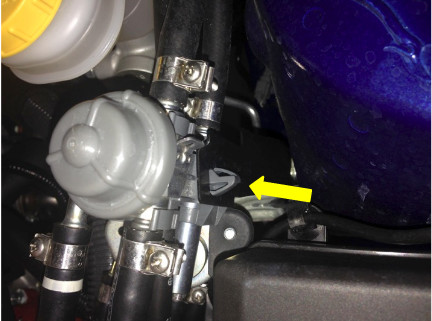
6. Remove the manifold pressure reference from the OEM FPR and remove the assembly from the engine bay. The factory FPR, dampers and hose assembly is no longer needed. Be careful as excess fuel may continue to
drain from the assembly.
Installation of COBB Fuel Pressure Regulator Kit
- Inspect the new components included with the COBB kit. If anything appears out of place, please contact COBB immediately and do not proceed with the installation.
- Assemble the return line by placing the fuel injection hose clamp and fuel line over the open regulator barb and secure the fuel injection clamp using a 7mm nut driver or flat head screw driver
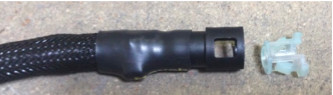
- To install the new fuel lines, remove the inner white cap from the from the connector with a pinching motion. Place the clip over the OEM fuel rail or line, "big side" first. Lubricate the new connector or line using silicone spray or similar, then gently slide the connector onto the fuel line until it clicks firmly in place. Note: DO NOT FORCE THE FITTINGS! Proper installation will require very little effort. The black connector and white clip must be oriented in the same direction for the connector to seat. If the connector and metal line are not properly aligned, damage to the connector's inner seals can occur.
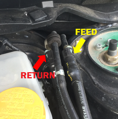
- Return Line Orientation – The longer section connects to the fuel rails, and the shorter section connects to the firewall. The regulator should be oriented so the vacuum port side is on the bottom and the bracket is sticking up
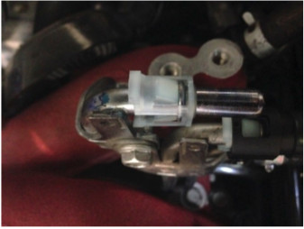
- Secure the regulator to the bracket that held the plastic line retainer using the provided rubber isolater and nuts, along with 2x 10mm wrenches or a 10mm wrench and socket. You may need to slightly bend the bracket towards the driver’s side fender if the regulator is touching the bracket at the bottom of the regulator.
- Feed Line Orientation – Install the feed line with the sheath covered section going towards the fuel rails.
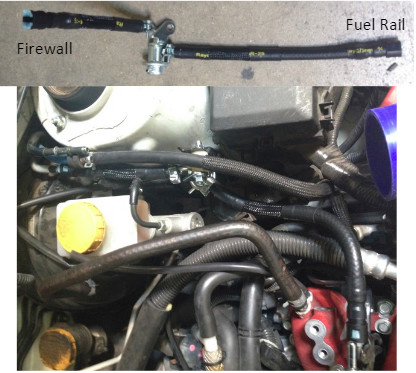
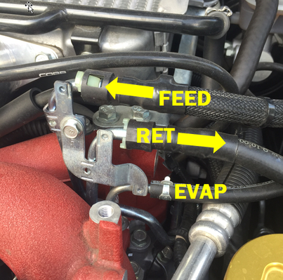
Fuel line feed/return orientation:
- Once installation is completed, reconnect the negative battery terminal and prime the fuel system by cycling the key between the “OFF” and “RUN” positions at 3-second intervals. 4 or 5 cycles will be adequate to re-pressurize the system. CAREFULLY INSPECT FOR LEAKS AND IMMEDIATELY CORRECT IF ANY ARE FOUND!
- Start the vehicle and again inspect for any leaking or abnormalities. Halt immediately if any fuel leaks or other issues are found!
- Installation of the Fuel Pressure Regulator Kit is now complete! We recommend inspecting for any signs of leaking or component deterioration periodically for safety and performance purposes. Enjoy your new COBB Tuning Fuel Pressure Regulator Kit!
Manifold Reference Relocation
The manfiold reference relocation allows for moving the fuel pressure regulator’s manifold pressure reference away from the #4 cylinder runner and into a plenum-based source, similar to the method used on the previous generation 2004-2007 STI. This helps prevent unwanted manifold pulsations from affecting the FPR as the plenum is a “common” area of the manifold that represents the average vacuum/boost of all cylinders rather than a singular cylinder.
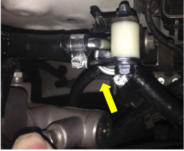
- Remove and set aside the factory rubber hose connected to the small nipple on the intake manifold runner for Cylinder #4. If the vehicle is equipped with an auxiliary boost gauge, like those offered as factory STI/SPT options or an aftermarket unit, we recommend that you now connect those devices directly to this port.Vehicles utilizing Hobbs switches and other similar devices that need a vacuum/boost reference can also be plumbed to this port. If no other devices are connected to the manifold for detecting boost/vacuum, you may cap this port with the included black vacuum cap.
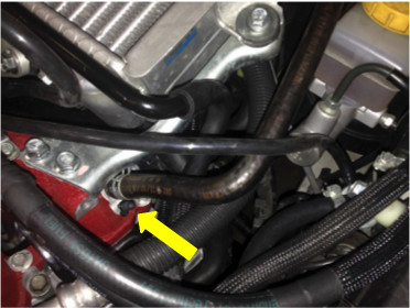
- Cut the OEM bypass valve (BPV) reference hose near the BPV but with adequate material left to allow easy insertion of the new COBB-provided “Tee” fitting. The larger ports will connect to the OEM hose on one side and back to the BPV on the other side using the provided 6mm black silicone hose; the small “Tee” port will now connect directly to the FPR using the provided 4mm black silicone hose. Trim hoses as necessary to allow for shortest length necessary to easily reach all components without being stretched or pinched.
Links
COBB Product Install Instructions for Subaru Vehicles
Main Installation Instruction Repository for Subaru Parts
Calibration Map Notes for Subaru Vehicles
Link to Subaru Map Notes to see what map you should be on given the parts you've added
COBB Customer Support Web Support and Tech Articles: COBB Tuning Customer Support Center Email: support@cobbtuning.com Phone support available 9am to 6pm Monday-Thursday. 9am to 4pm Friday (CST) 866.922.3059 return to www.cobbtuning.comContact Us:
Related content
Copyright 2025 © COBB Tuning Products LLC. All Rights Reserved. | www.cobbtuning.com