843615 - Air/Oil Separator Subaru WRX 2015-2020
- Brandyn Mowat

843615 - Air/Oil Separator Subaru VA WRX
Subaru WRX 2015 - 2021
%20(1).jpg?version=1&modificationDate=1602190866336&cacheVersion=1&api=v2&width=650&height=650)
Congratulations on your purchase of the COBB Tuning Air Oil Separator! The following instructions will assist you through the installation process. Please read them BEFORE beginning the install to familiarize yourself with the steps and tools needed. If you feel you cannot properly perform this installation, we HIGHLY recommend you take the vehicle to a qualified and experienced automotive technician.
Table of Contents
Parts List
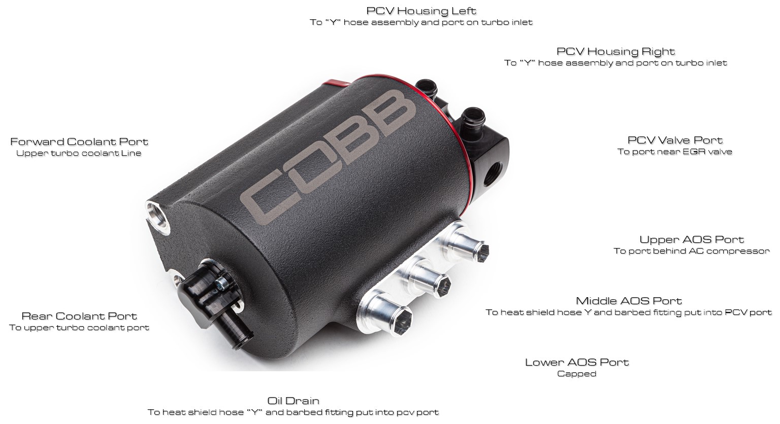
- Air/Oil Separator
- (43") Top coolant hose assembly with bleeder valve 1/2" ID -8ORB
- (15") Bottom coolant hose assembly 1/2" ID -8ORB
- Block Breather Hose Assembly 44" 1/2" hose combined with a 90° fitting
- Oil drain and lower Breather hose assembly
- Upper recirculation housing and o-ring (preinstalled)
- Recirculation hose assembly 30" hose 5/8" ID with Y fitting
- AOS Drain Fitting
- 1/2" Spring Clamp
- Mounting Bracket
- (3) M6x10mm bolt
- 5/8" High temp cap
- 1/2" High temp cap
- (20) 8" Zip tie
- ECU Relocation bracket
- (2) M6x20mm Bolts
- (2) M6 Washers
- 3/8" 90°plastic fitting
- (23") 3/8" PCV Hose
- 3/8" NPT to 5/8" Brass barb fitting
- (2) M6x12mm bolt
Tools Needed
- Phillips head screwdriver
- Flathead screwdriver
- 3/8" 19mm socket
- 1/4" Allen socket
- M3 Allen Socket
- M5 Allen Socket
- 10mm combination wrench
- 12mm combination wrench
- 7/8" combination wrench
- 11/16" combination wrench
- Trim removal tool
- Hose cutter
- Electrical Tape
A Special Note on Hose Installation
When installing the hoses and lines to and from the COBB Air Oil Separator, take special care to route them away from any sources of heat, ensure that they are free of kinks or obstructions, and secure them properly with zip ties to prevent movement and chafing. Additionally keep in mind that the engine will move slightly so leave a small amount of play in the lines where it goes up to the AOS to allow for some movement without causing damage or stress on the lines.
Quick Reference
Instruction By Vehicle
- Park your vehicle in a flat, level area.
- Using a 10mm wrench disconnect the negative of the battery.
Top Mount Intercooler Removal
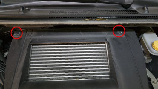
- Remove the two trim clips from the top corners by pulling out on the center portion using a trim tool or flat-blade screwdriver.
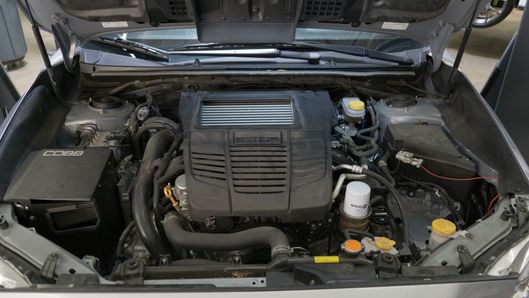
- Remove the engine cover by lifting from the back and pulling it towards you at the front.
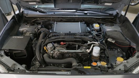
- Remove the 8mm hose clamp securing the factory charge pipe to the passenger's side and pull the pipe free.
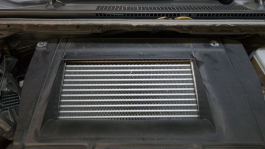
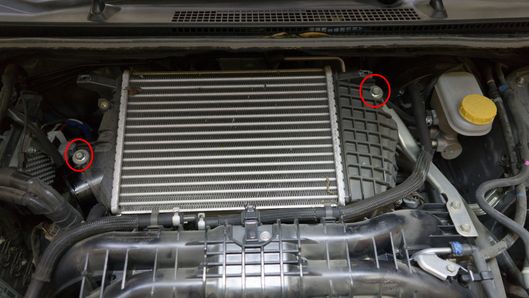
- Remove the 3 12mm bolts holding the intercooler down at opposite corners.
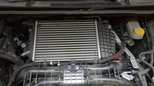
- Remove the driver's side intercooler support bracket.
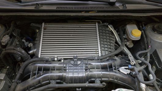
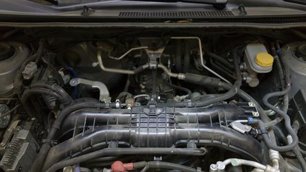
- Gently lift and remove the intercooler from the engine bay.
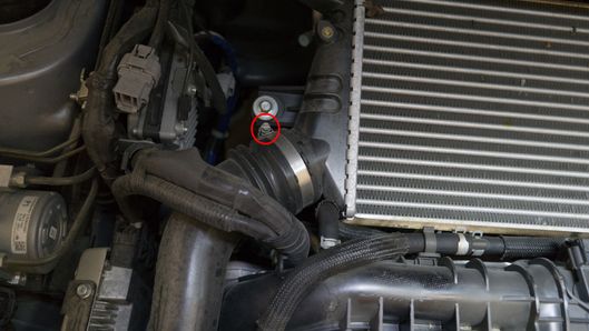
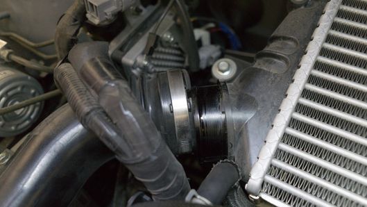
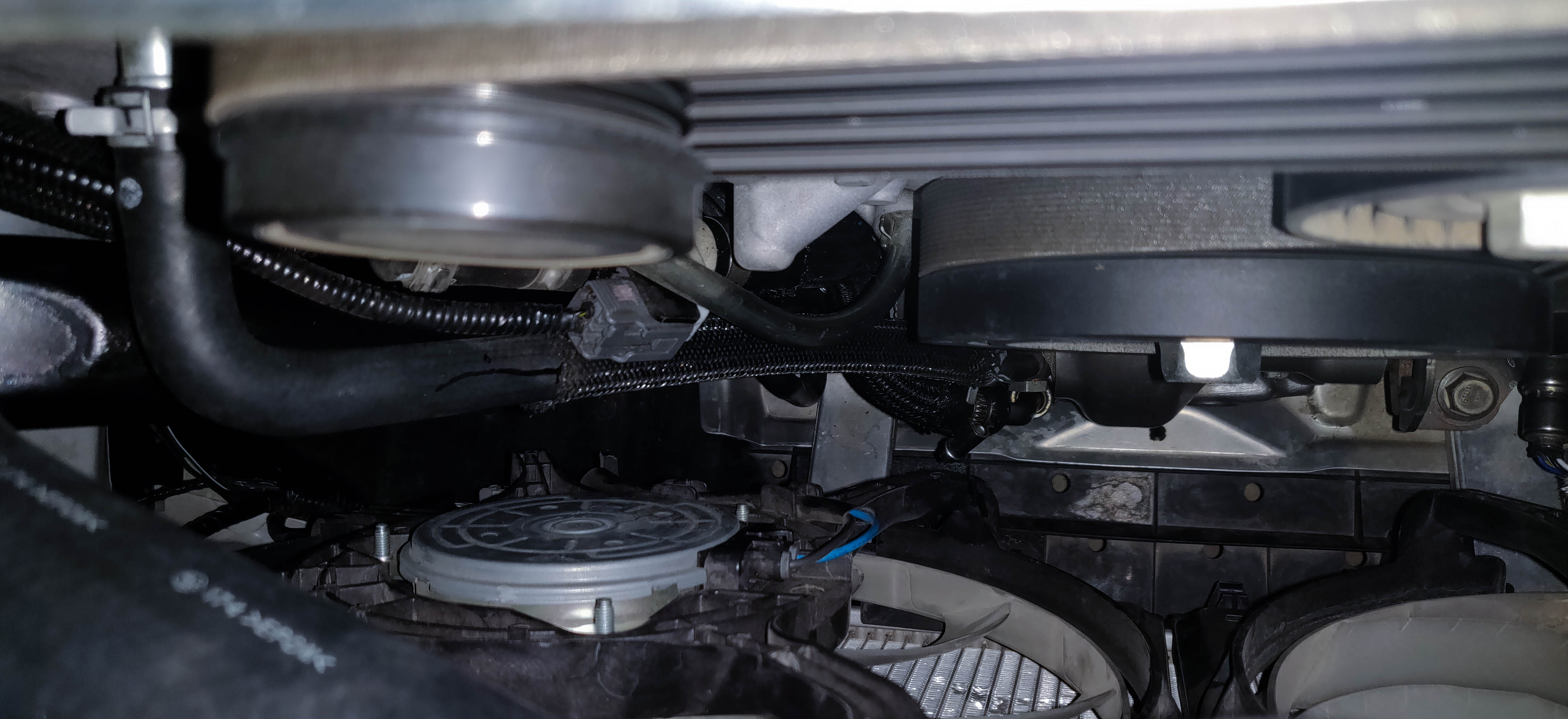
Charge Pipe Removal
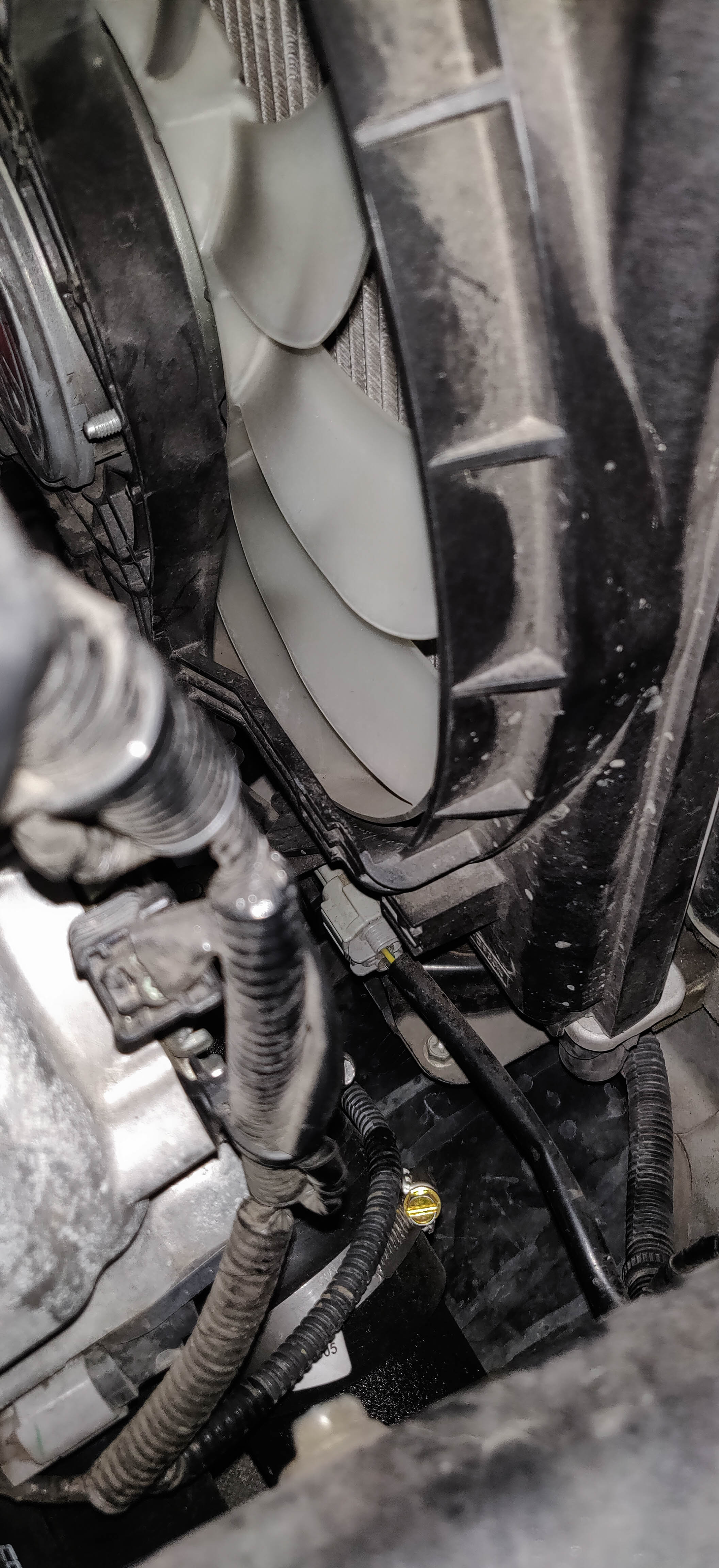
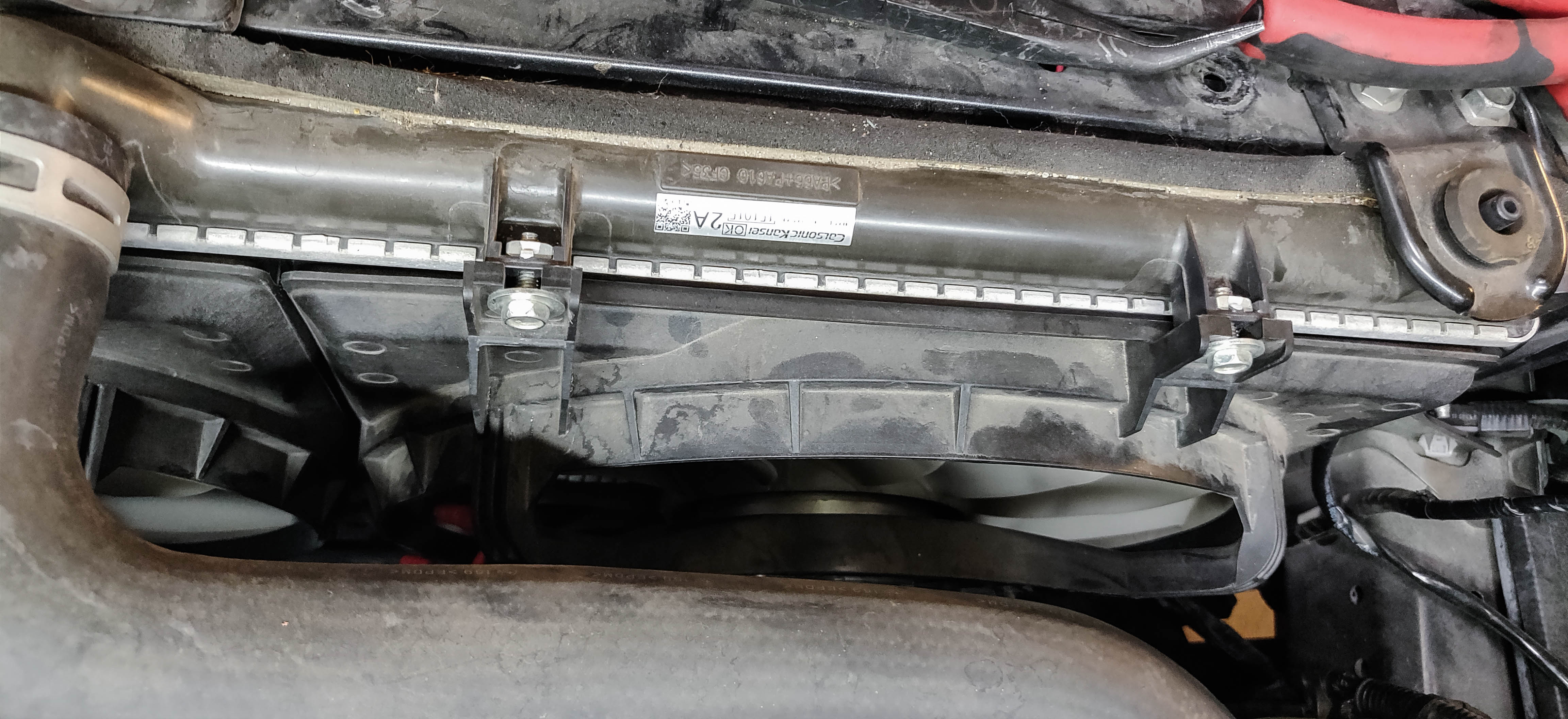
- To get more room for this step and the next, we'll remove the radiator fan on the passenger's side (USDM) Undo the wiring connector on the side at the bottom and unbolt it at the top using a 10mm socket before lifting the entire fan out of the car.
- Loosen the BPV to factory hot pipe clamp as well as the one going to the inlet.
- Remove (2) 12mm bolts on the factory hot pipe to turbo. You will need a 6" extension for one of the bolts.
- Applying a small amount of pressure, remove the BPV from the turbo inlet.
- Pull the BPV away from the factory hot pipe.

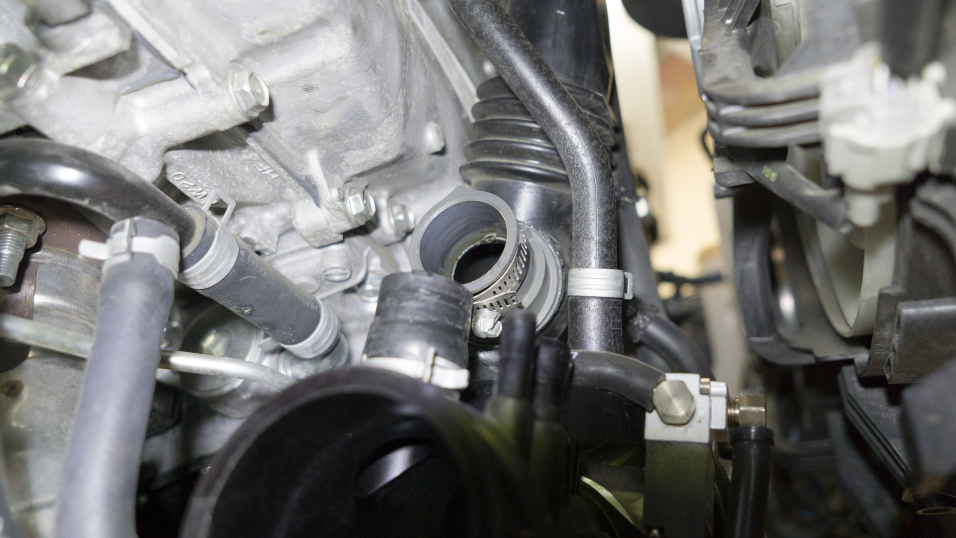
- Loosen the clamp from the intercooler to hot pipe.
- Remove the hot side pipe. Be cautious of the pin and grommet near the intake manifold so make sure to lift it straight over that.
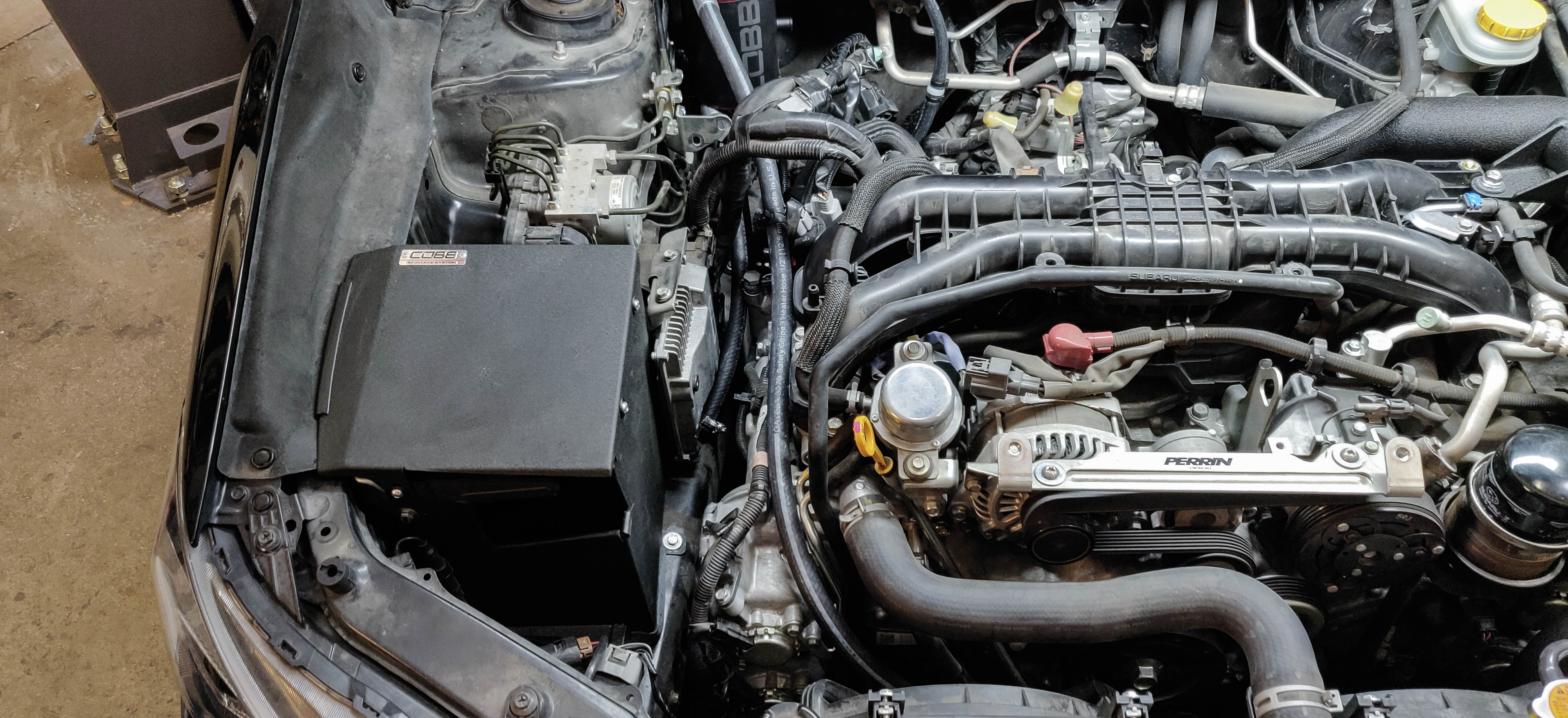
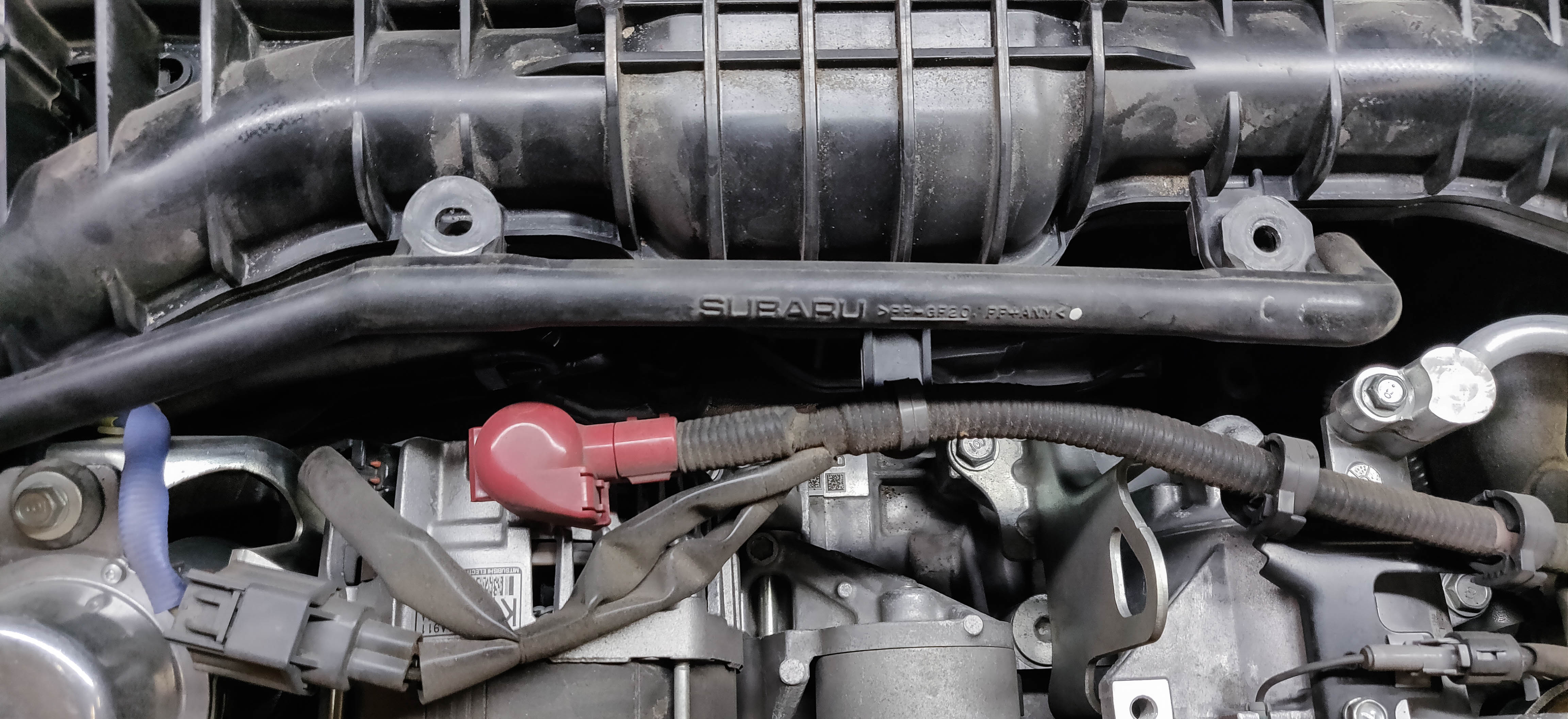
Power Steering Control Module Relocation
15-16 modules have a power steering control module in this location. For 17-18 models you won't have to tackle the wiring or control unit, however the black metal bracket will still need to be removed.
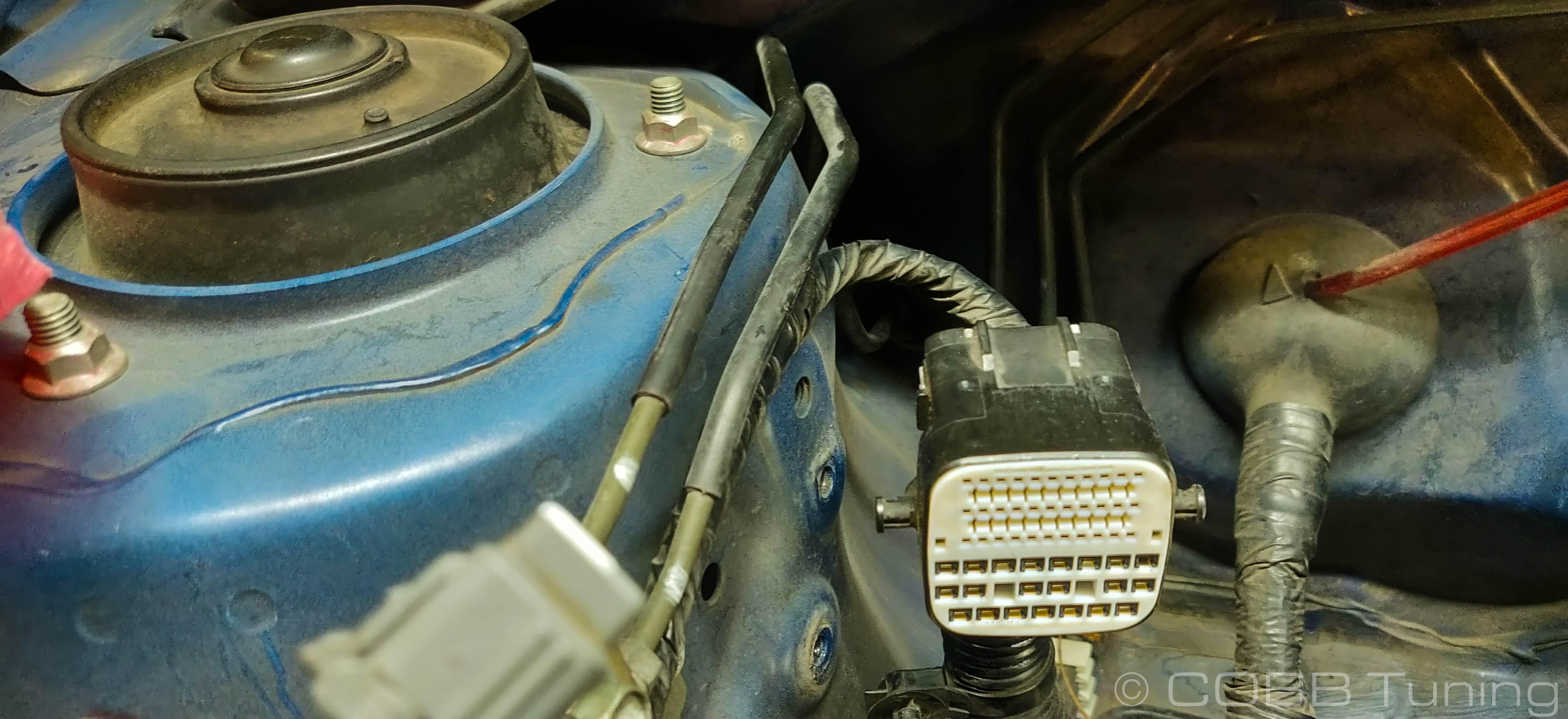
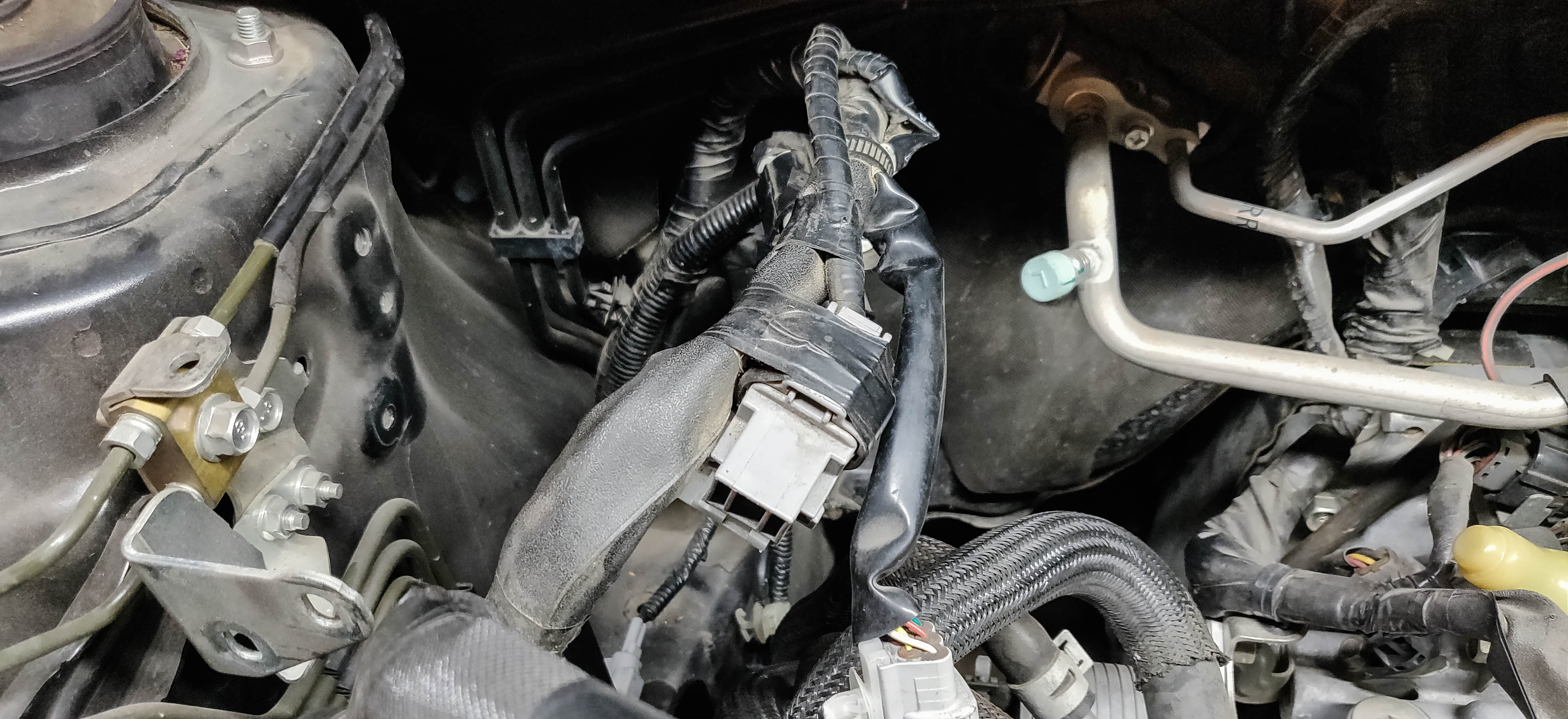
On the rear passenger's side (USDM) of the vehicle's engine bay. Locate this control module. Carefully disconnect the various connectors on it.
The wires going to the control module are designed to move a significant amount of current. You MUST disconnect the battery prior to removing these connectors or risk damage to yourself or the vehicle.
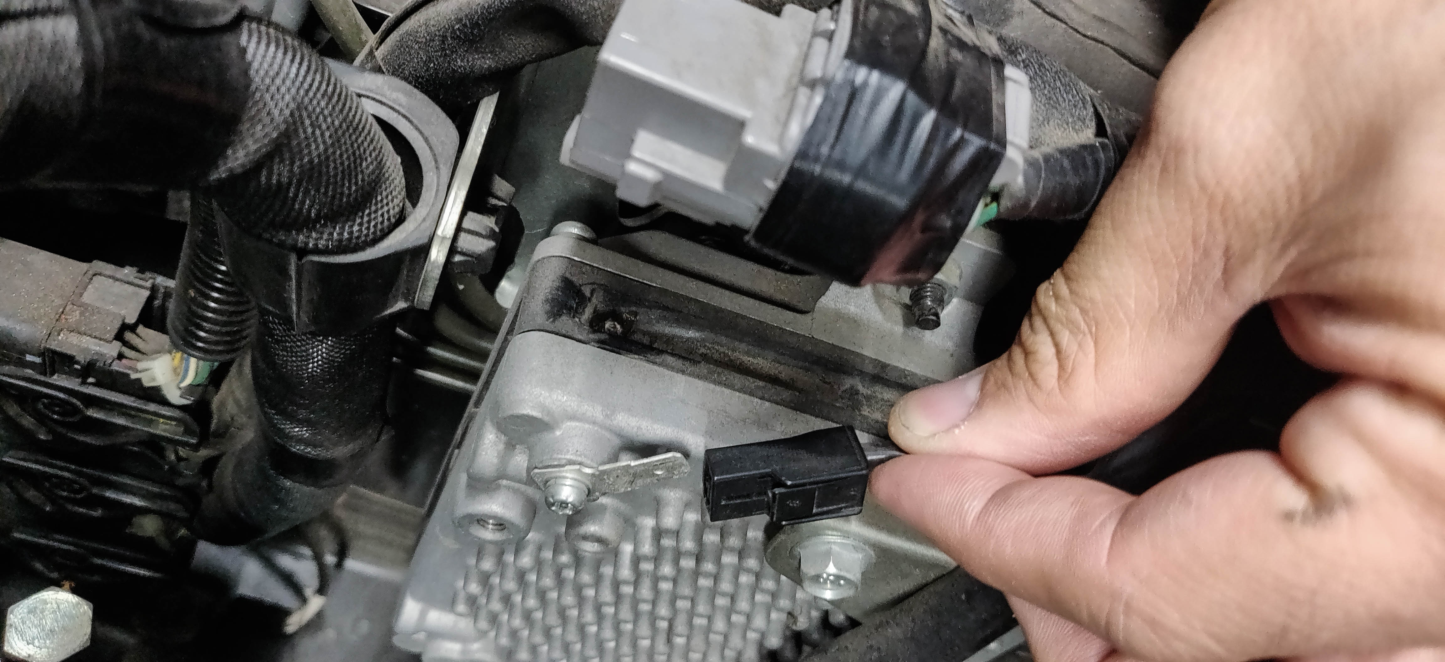

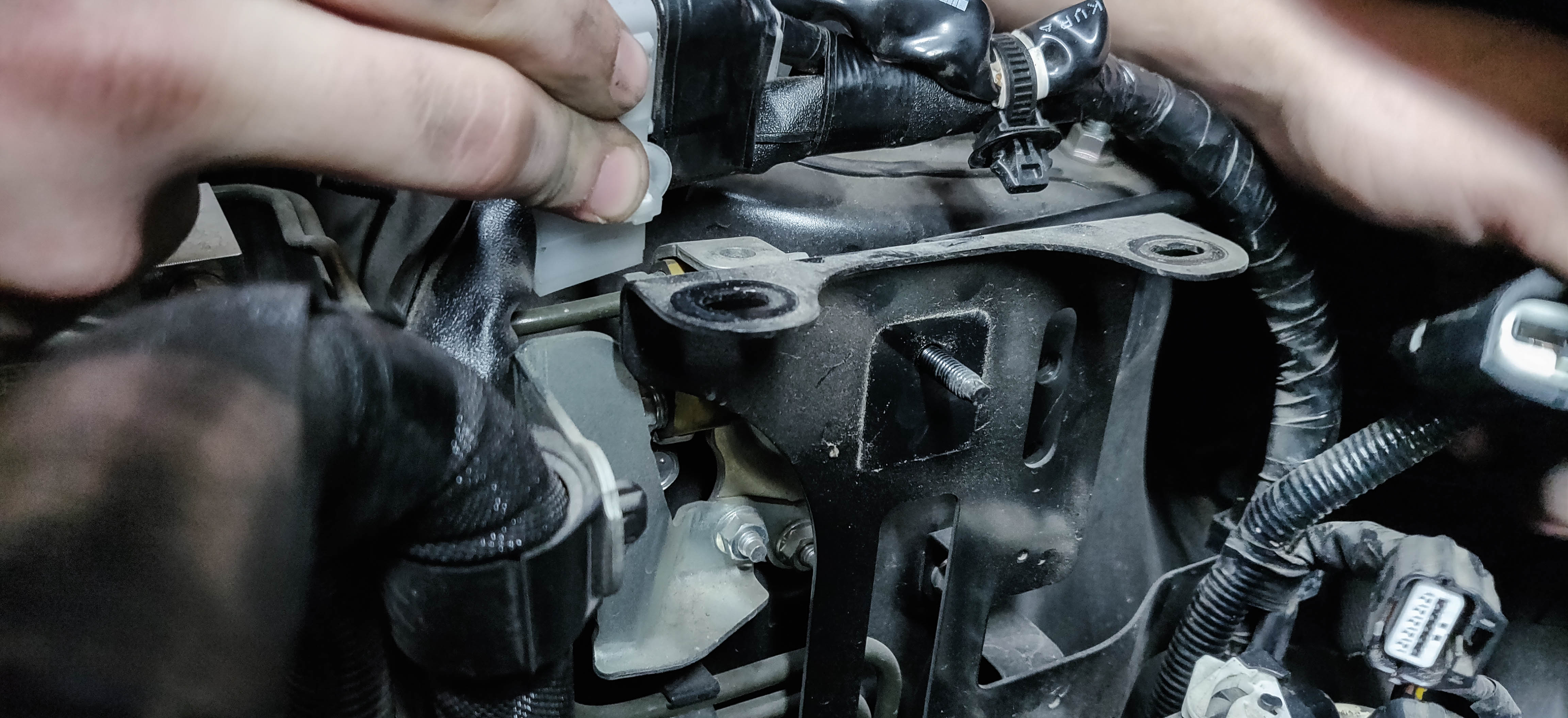
- Remove the grey connector from the bracket mounted on the control unit. The bracket can be removed with a 12mm socket and set aside.
- Unbolt the top and bottom bolts on the control unit using a 10mm socket and set the unit somewhere safe.
- Unclip the remaining harnesses from the black bracket and unbolt it from the car using your 10mm socket on the three remaining bolts attaching it to the car.
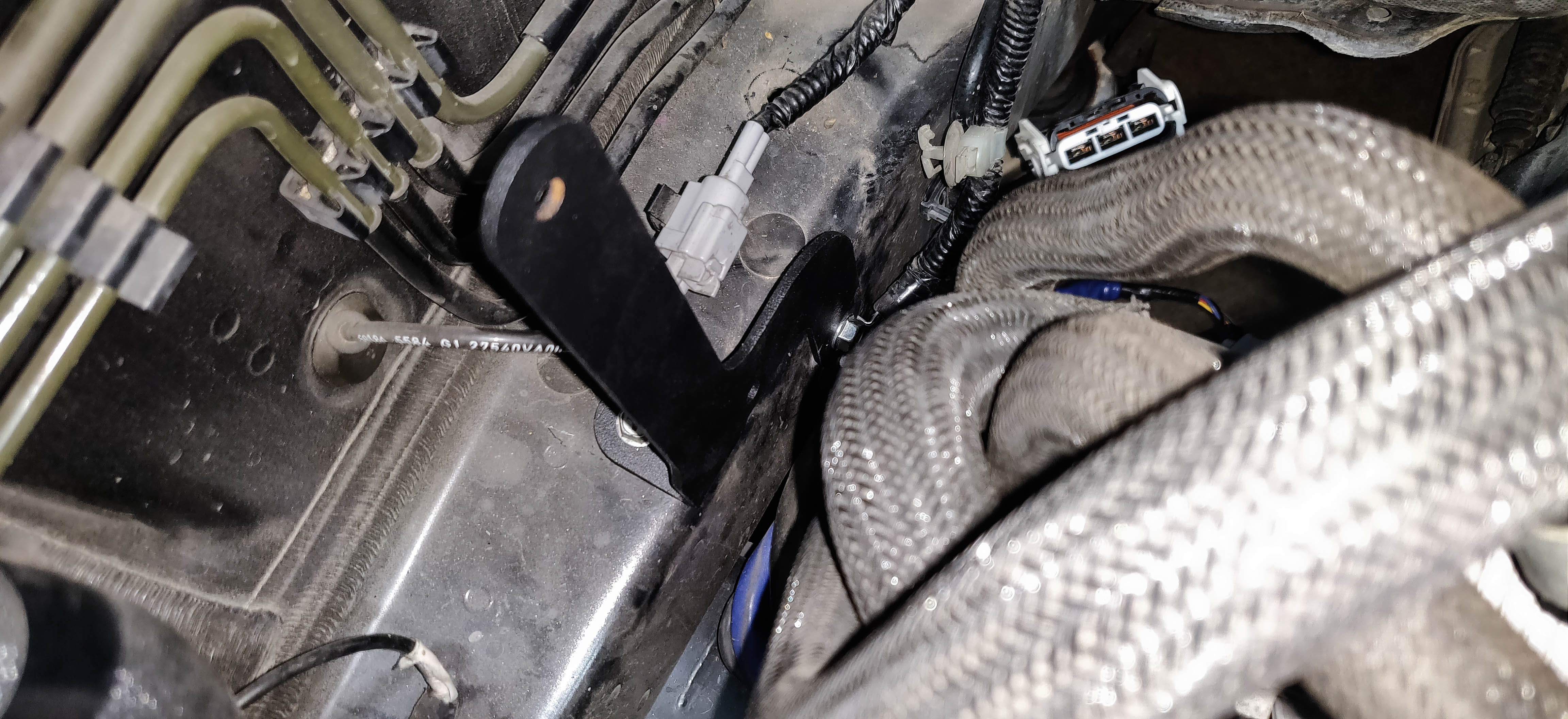
- On the framerail nearby locate a ground strap and a black plug beneath it. The plug can be removed using a trim tool and the ground strap relocated to it's space using your 10mm again.
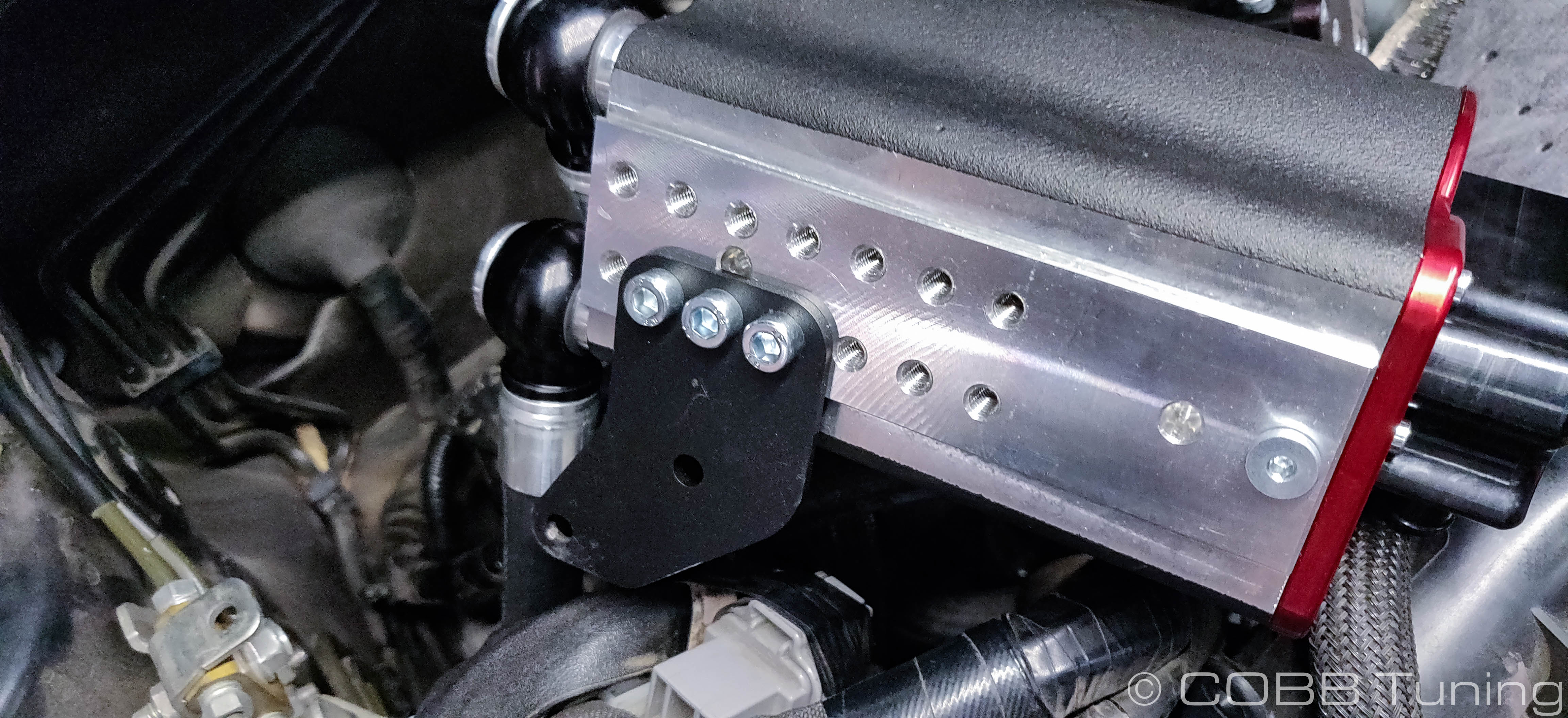
- Using the provided m6 bolts and the original nuts, mount the control unit to the provided bracket.
- Bolt the bracket and control unit to the newly-freed bolt holes on the frame. (Shown without control unit so you can more easily see where it bolts to.)
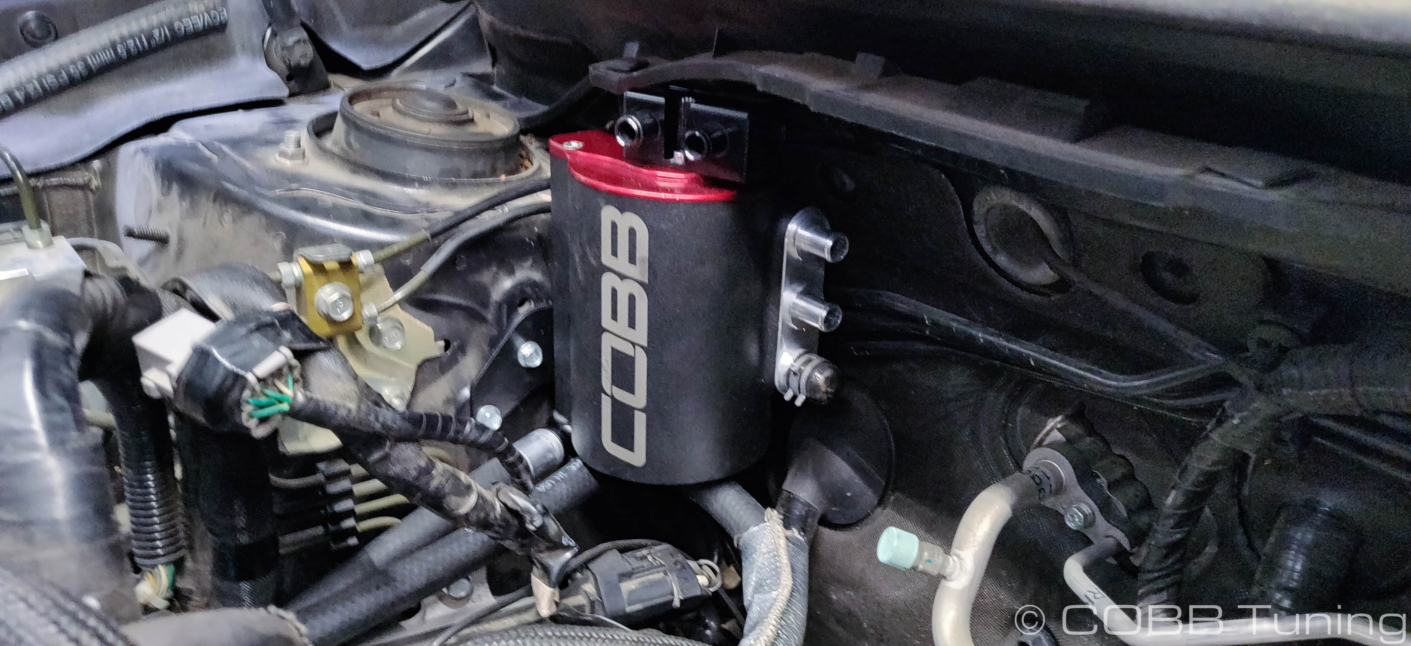
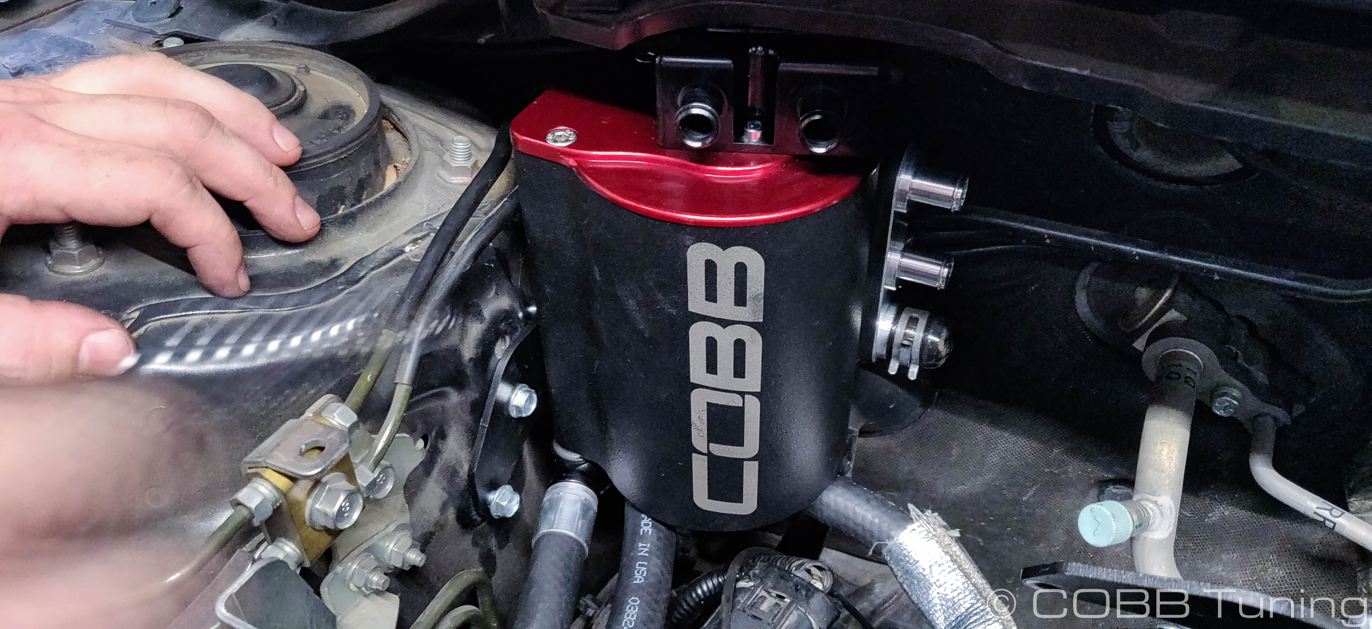
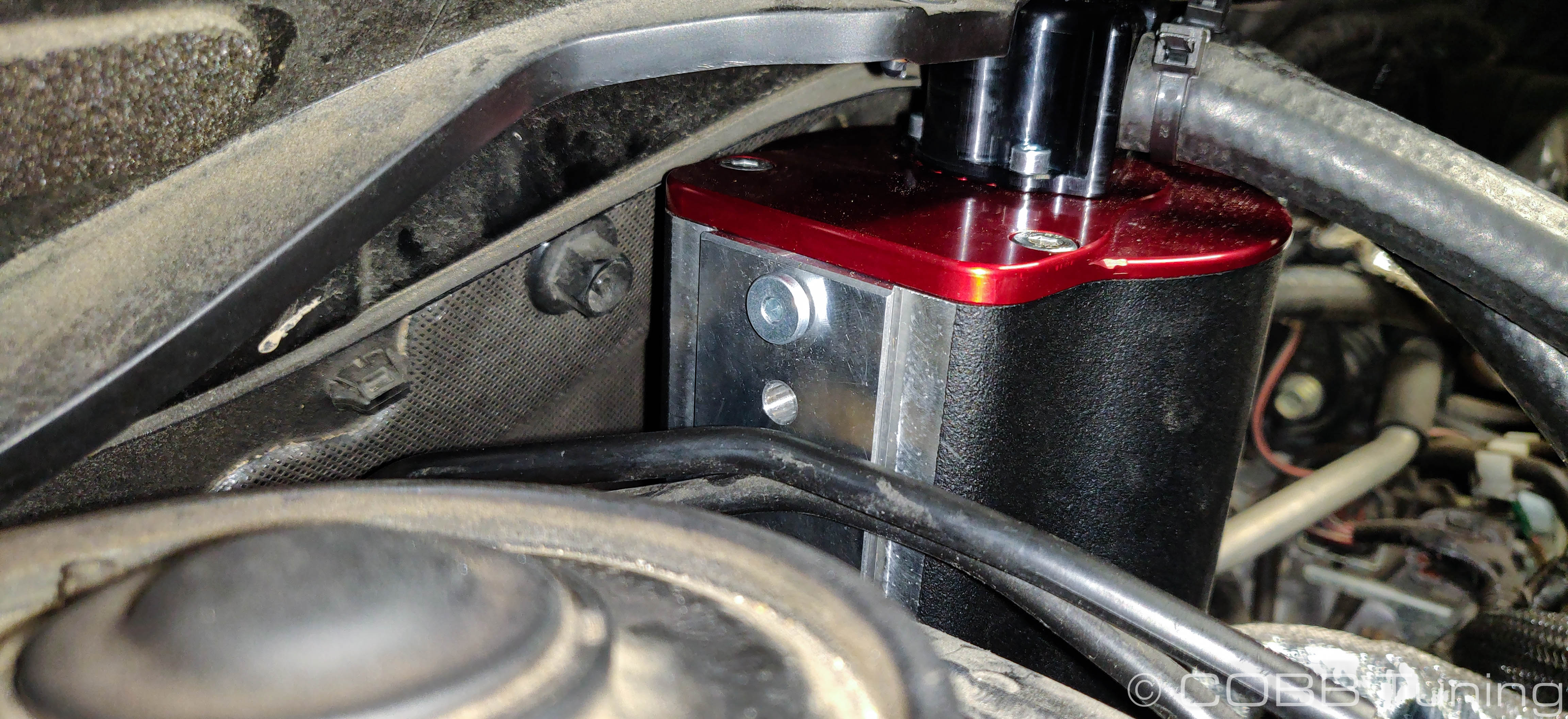
Install AOS Unit
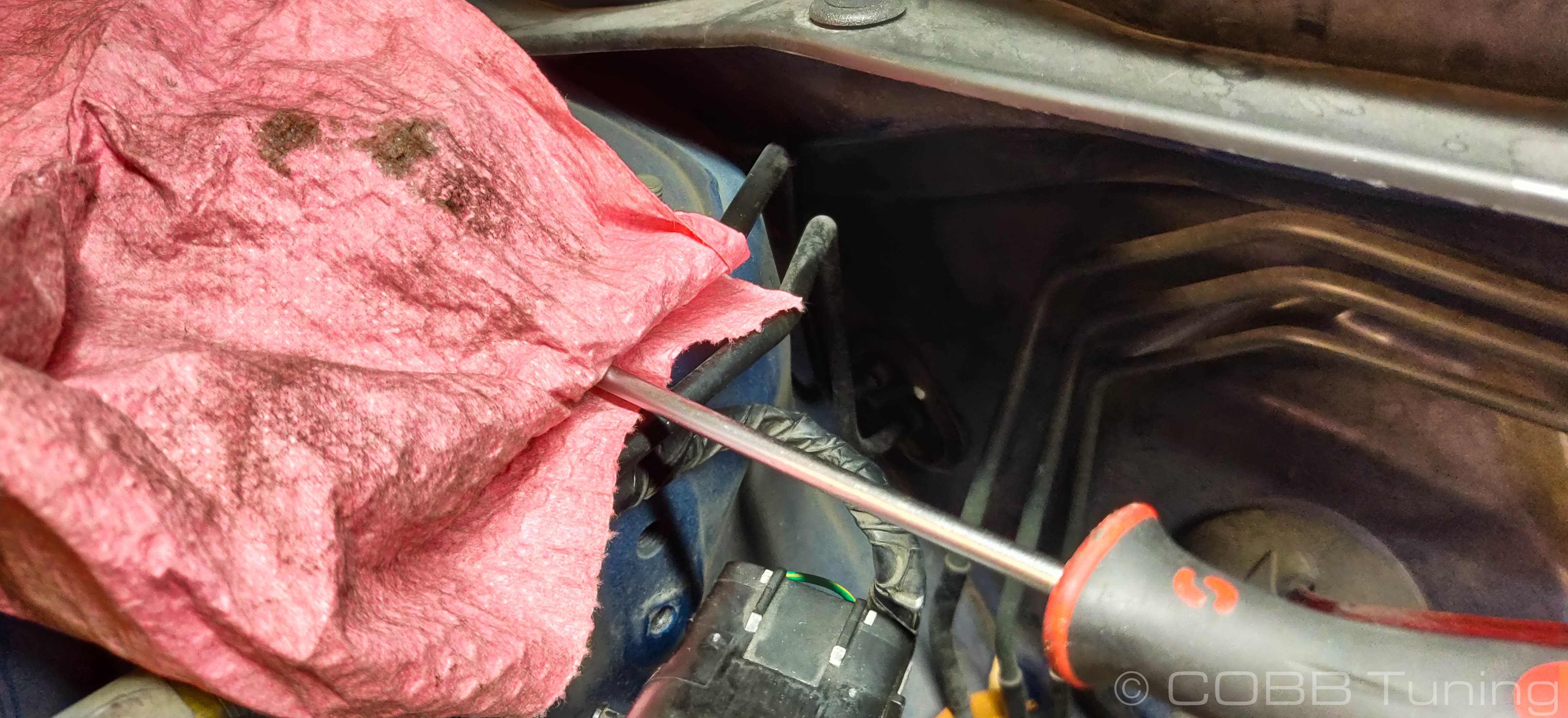
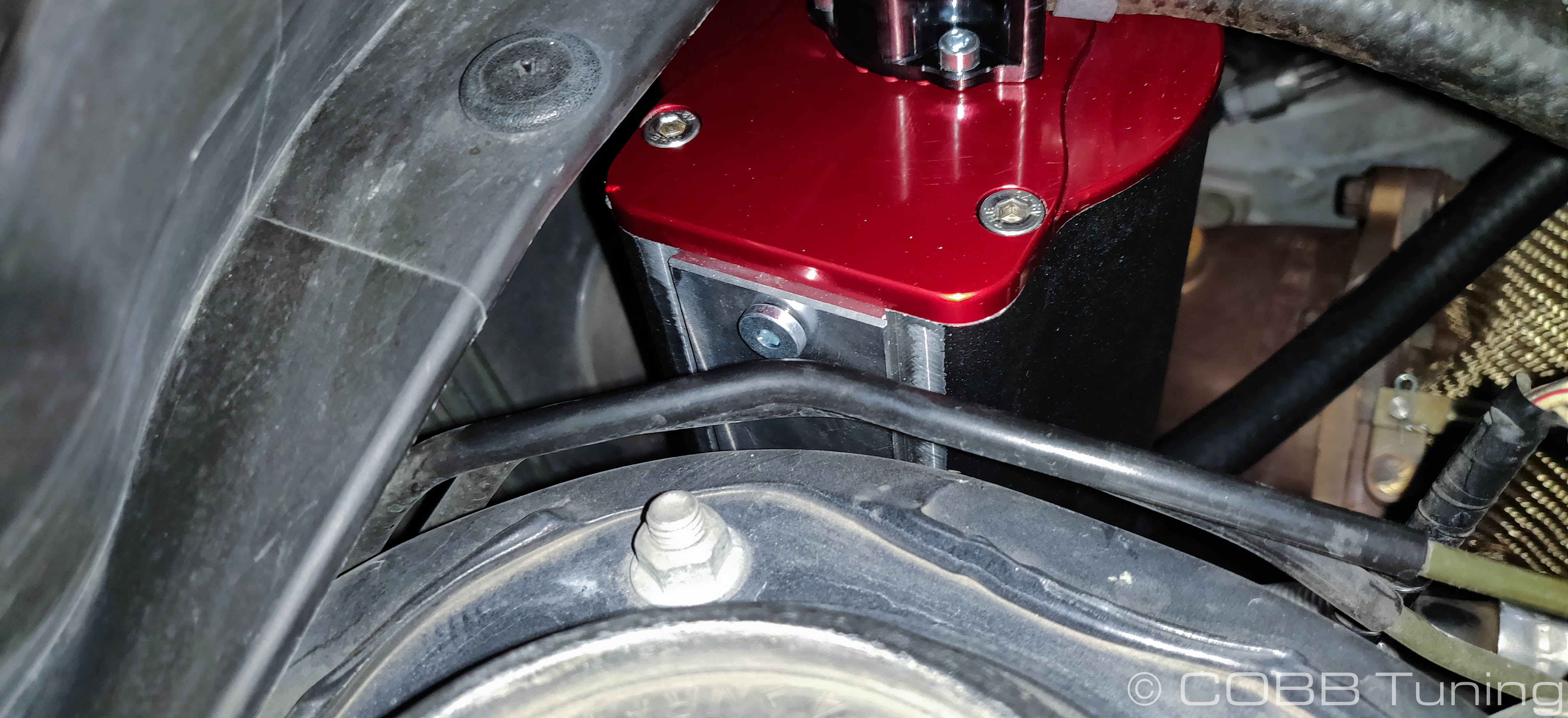
- Bend your brakelines up so that that they are over the level of the top of the strut tower. It's recommended to do this slowly, covering the lines with a rag and moving them one at a time with a screwdriver or small pry bar.
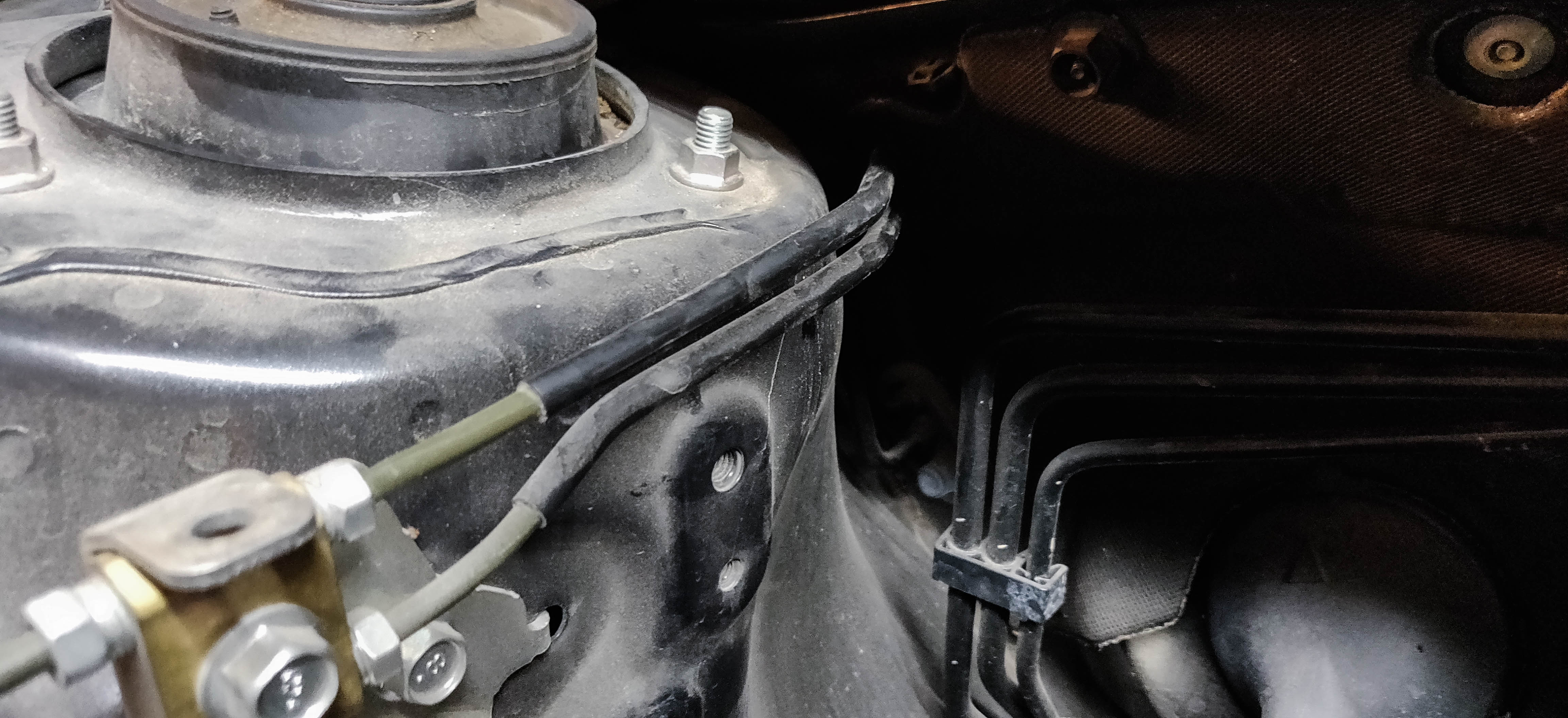
- Install the AOS bracket pointing downwardsin the second from the bottom hole.
- Install the two coolant lines into the bottom of the AOS using a 10mm allen socket tighten to 8nm (6 ft/lbs).
.jpg?version=1&modificationDate=1602191178934&cacheVersion=1&api=v2&width=288&height=250)
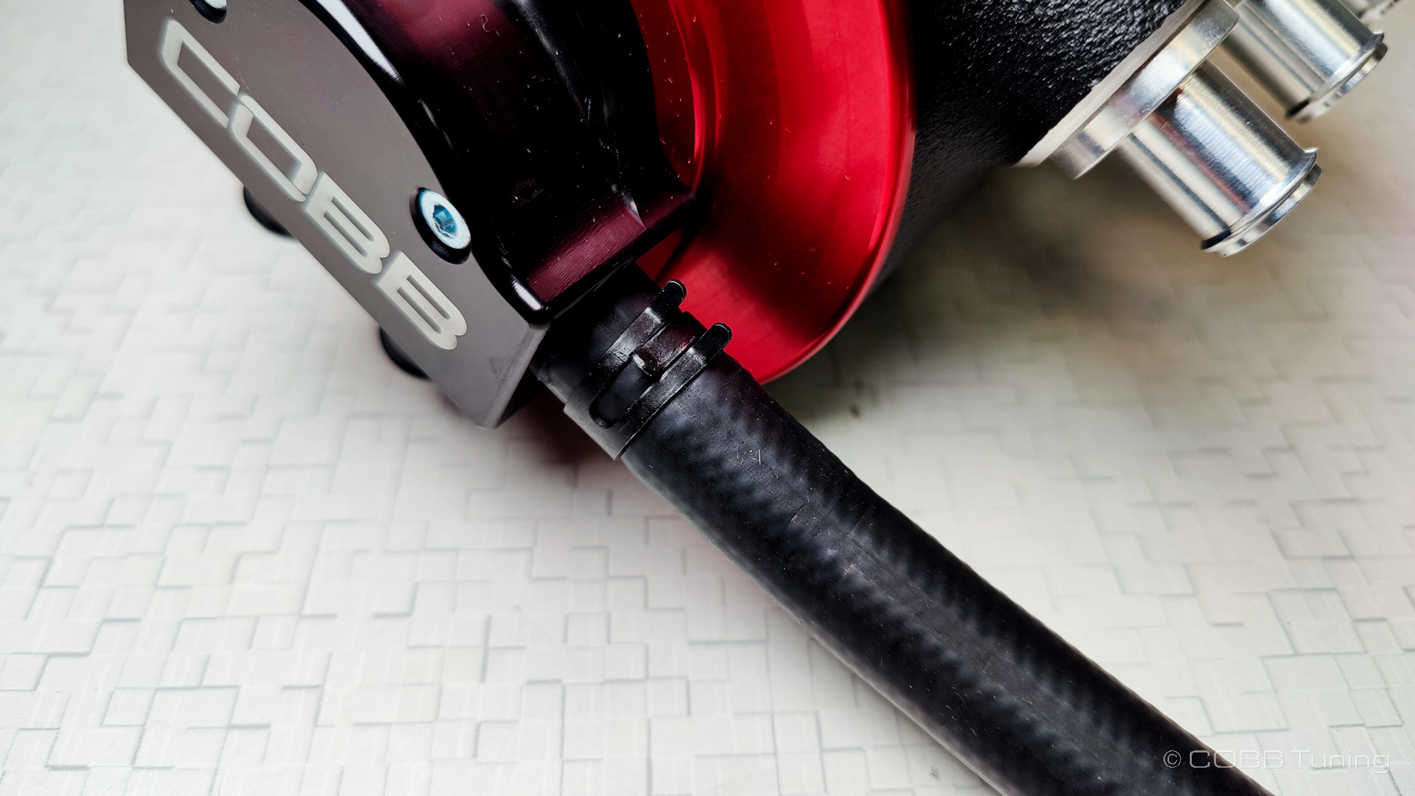
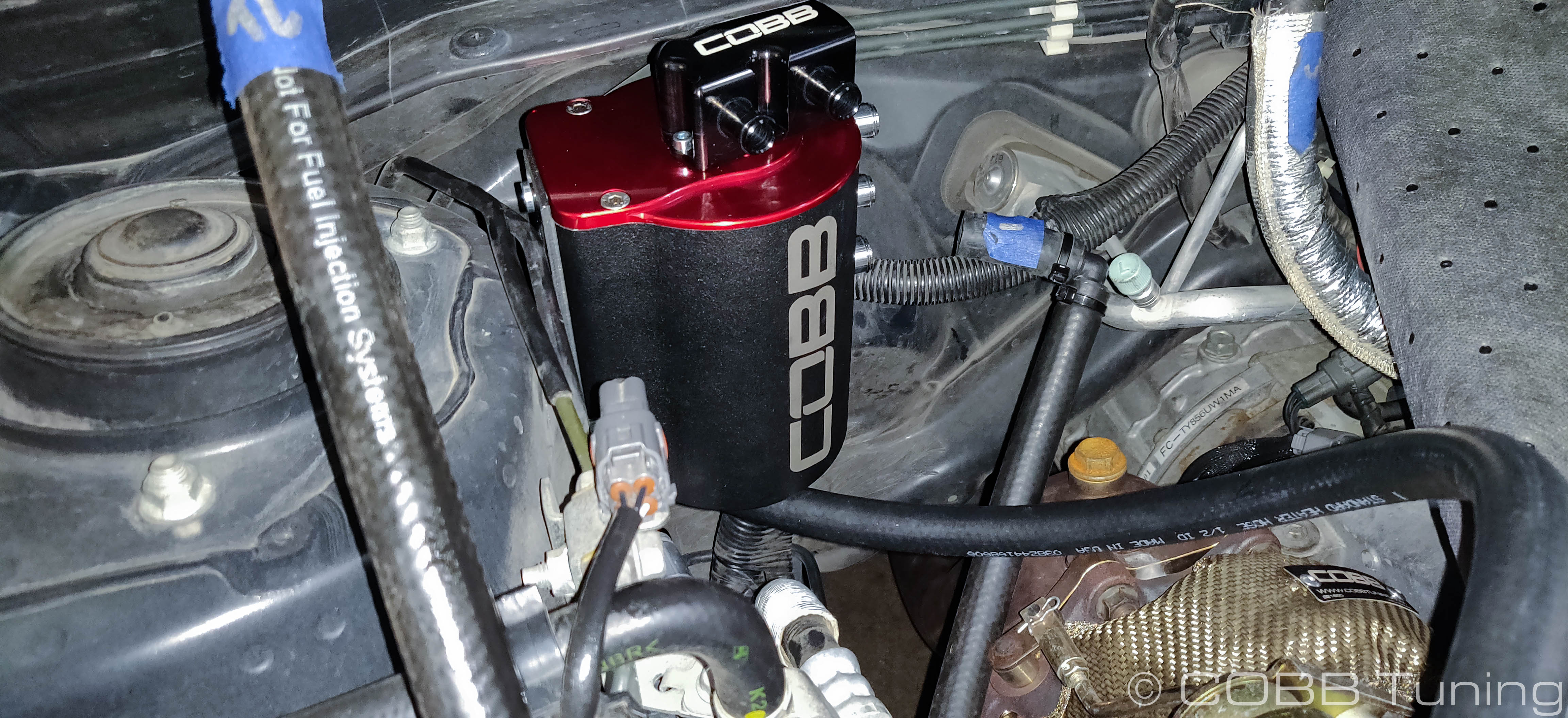
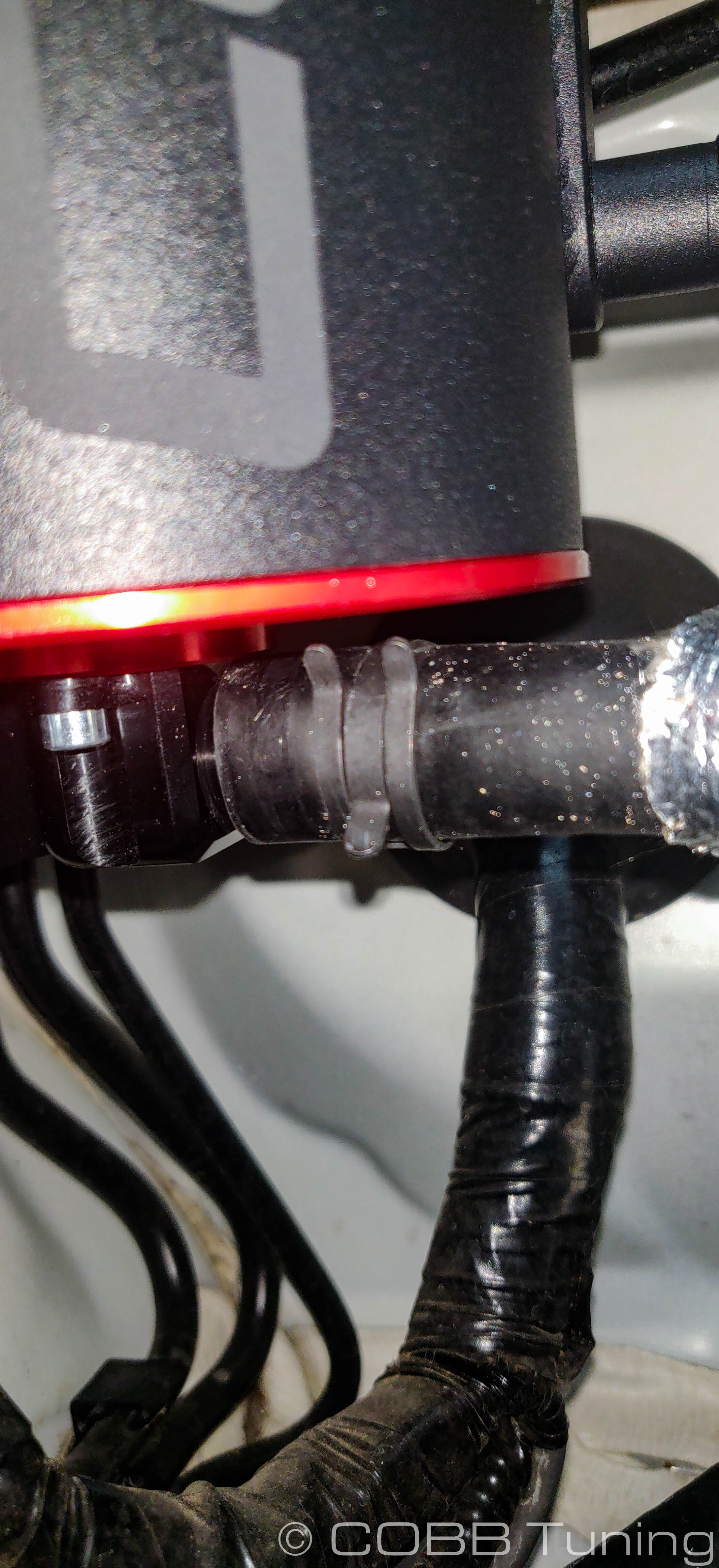
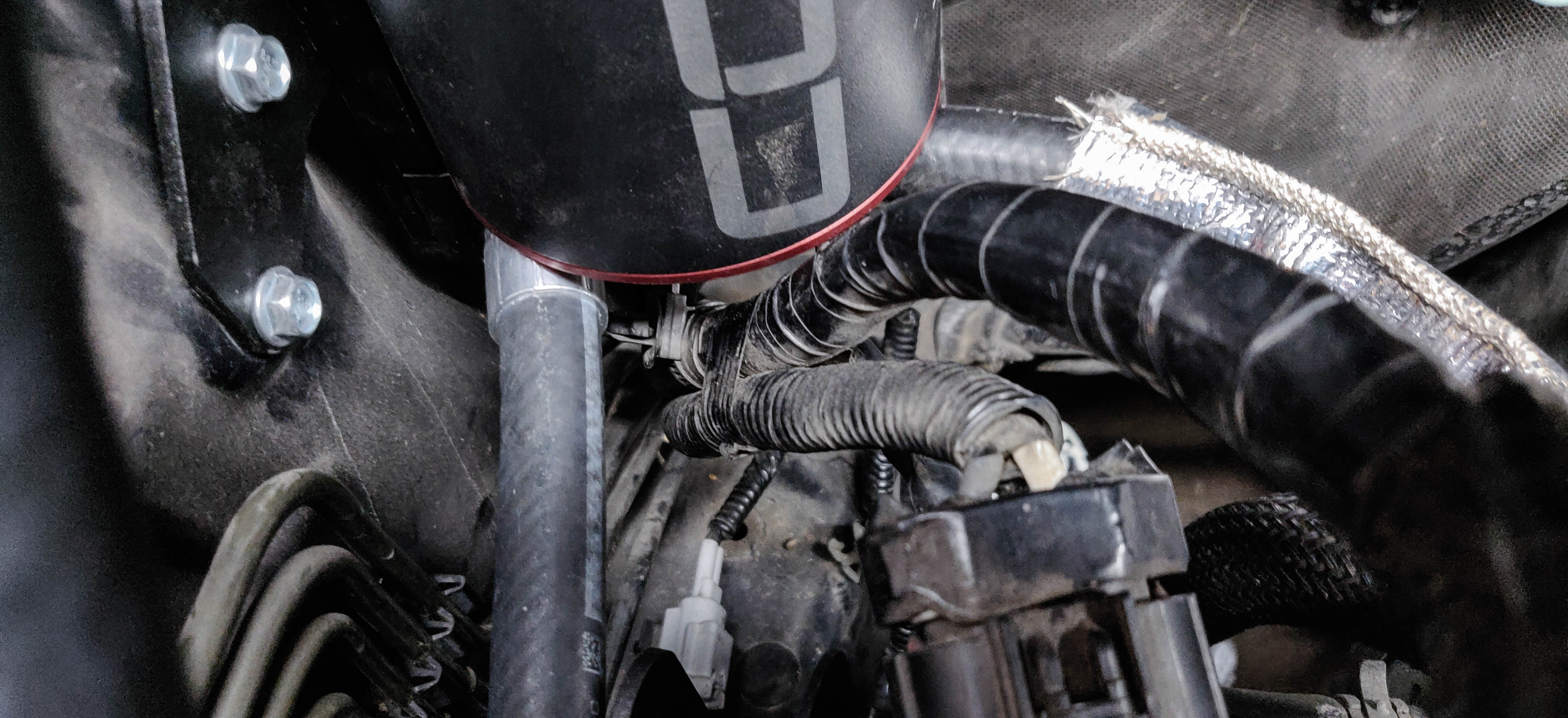
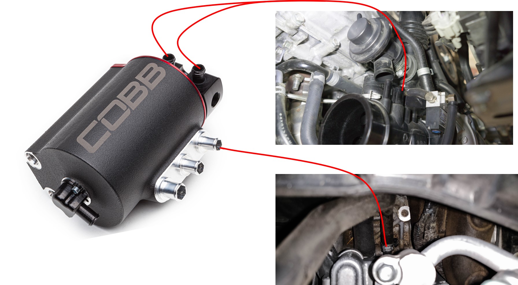
- Add the provided PCV line into the PCV housing port by the COBB logo securing it with a spring clamp. Make sure that the arrow on the PCV valve is pointed towards the engine.
- Bolt the unit into the car over the matching bolt holes on the strut tower using the original m6 bolts. Double check that you have enough clearance for the bleeder port on the back side near the brake lines, if not you may need to adjust them further.
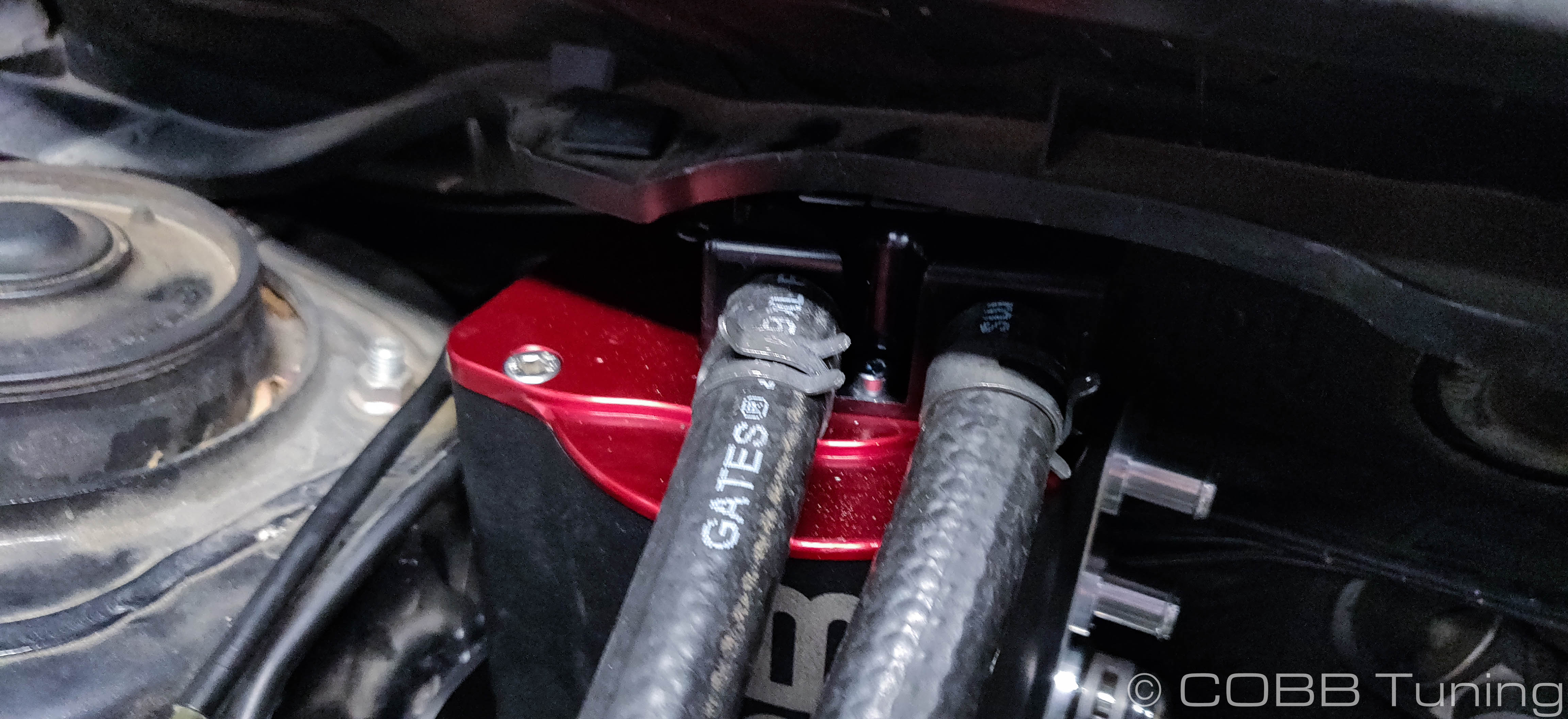
Coolant Line Installation
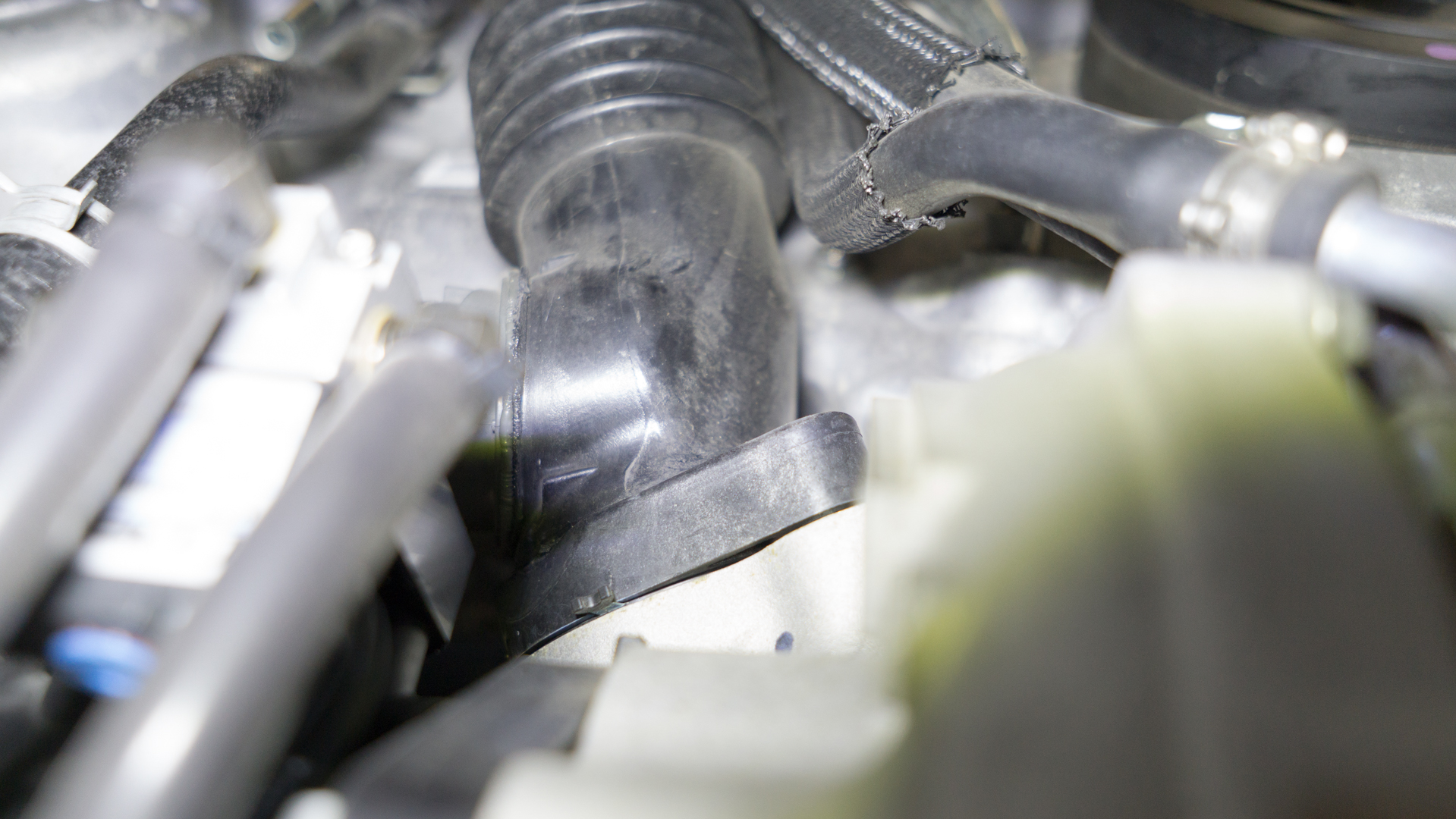
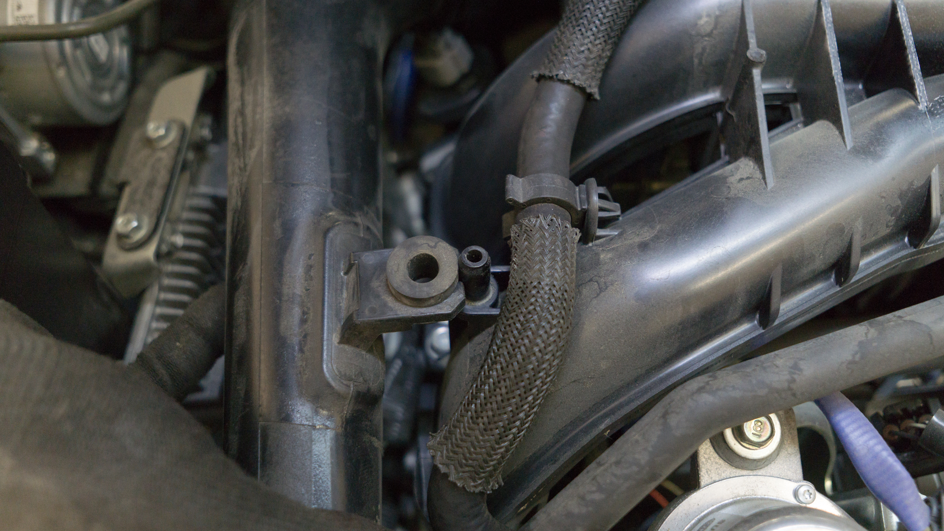
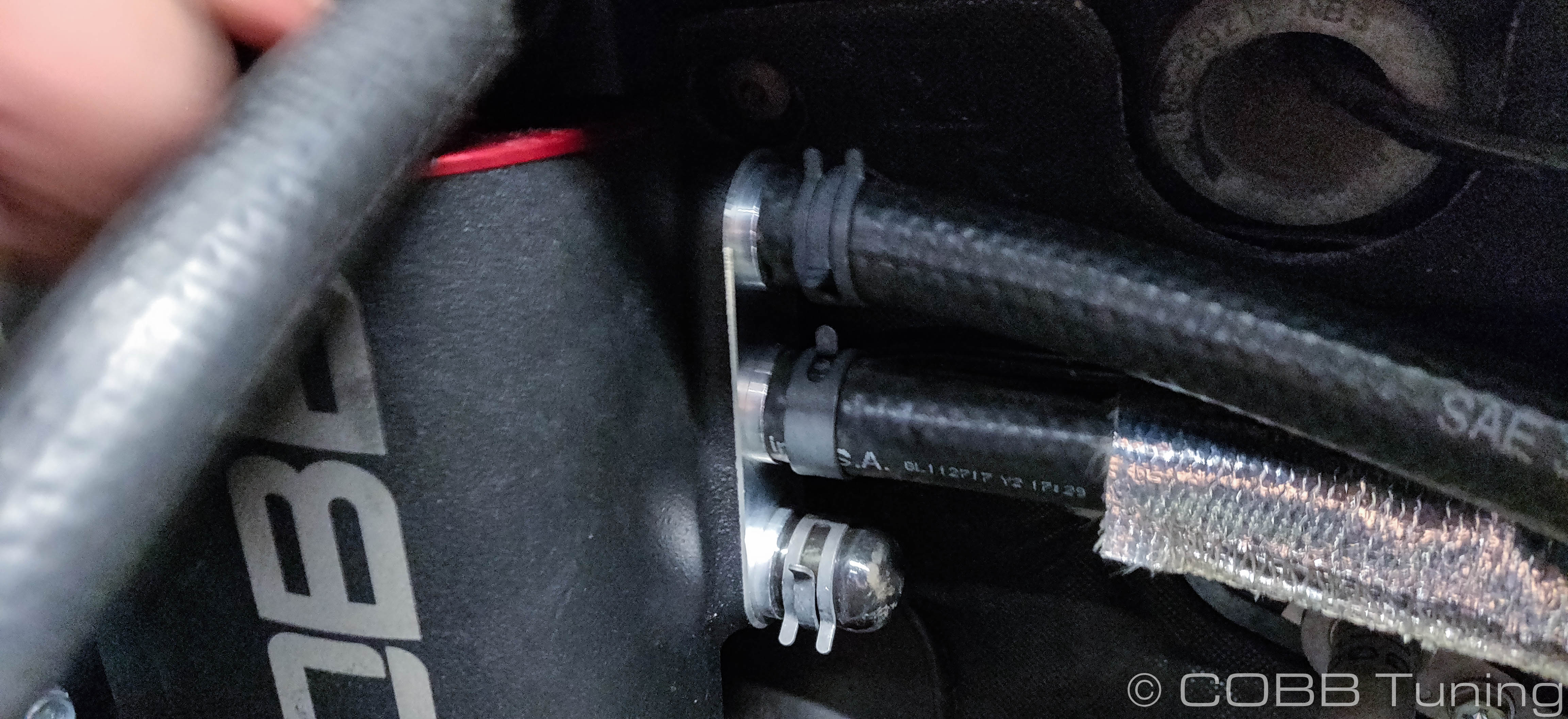
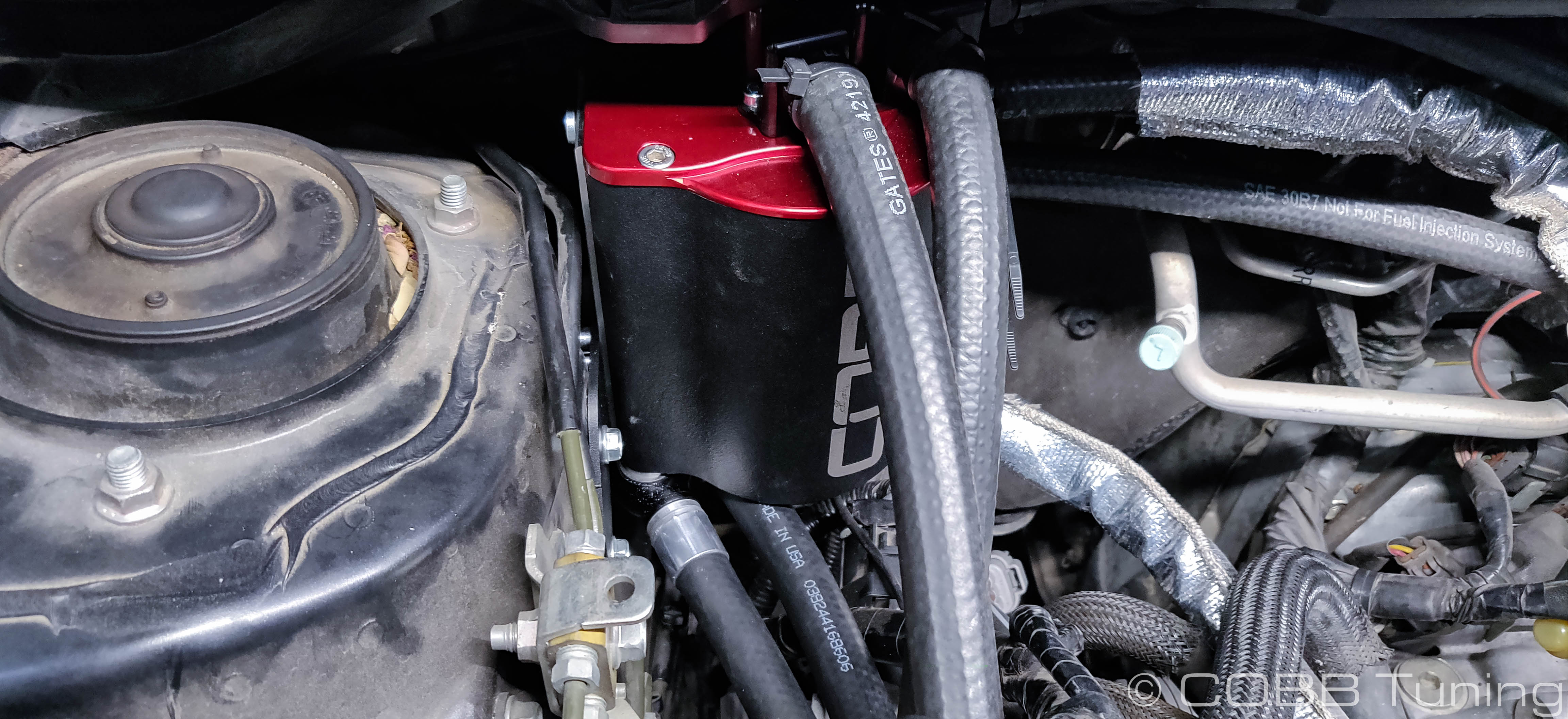
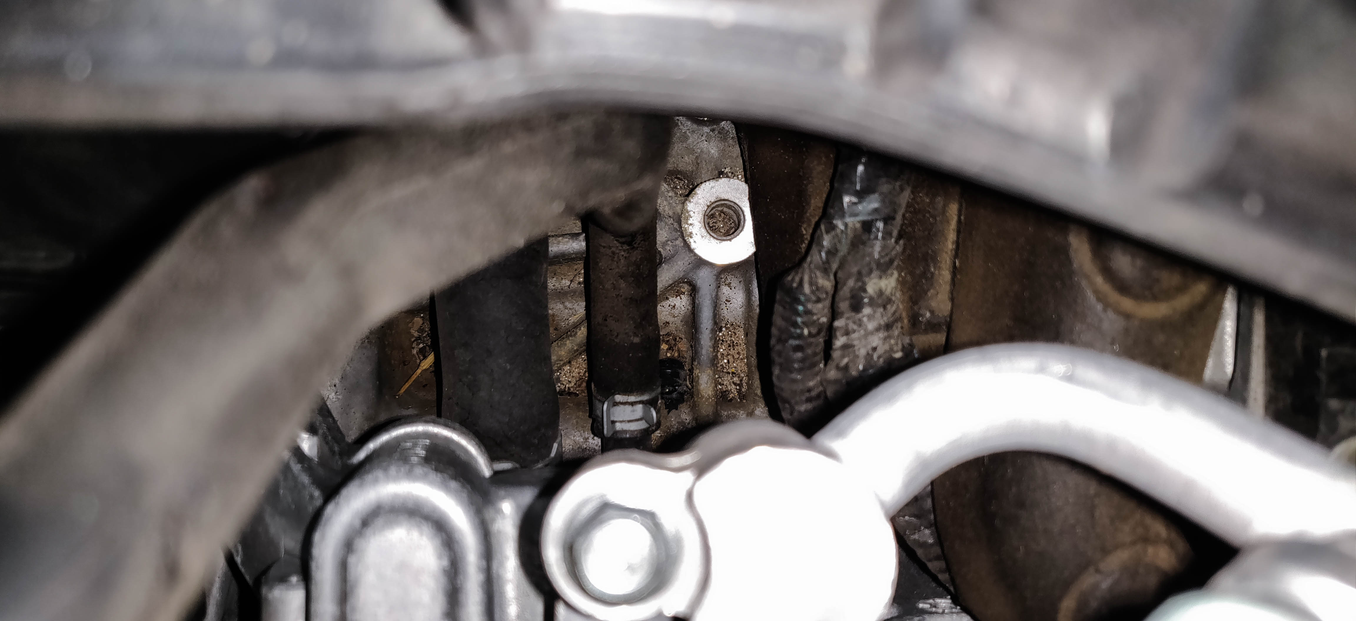
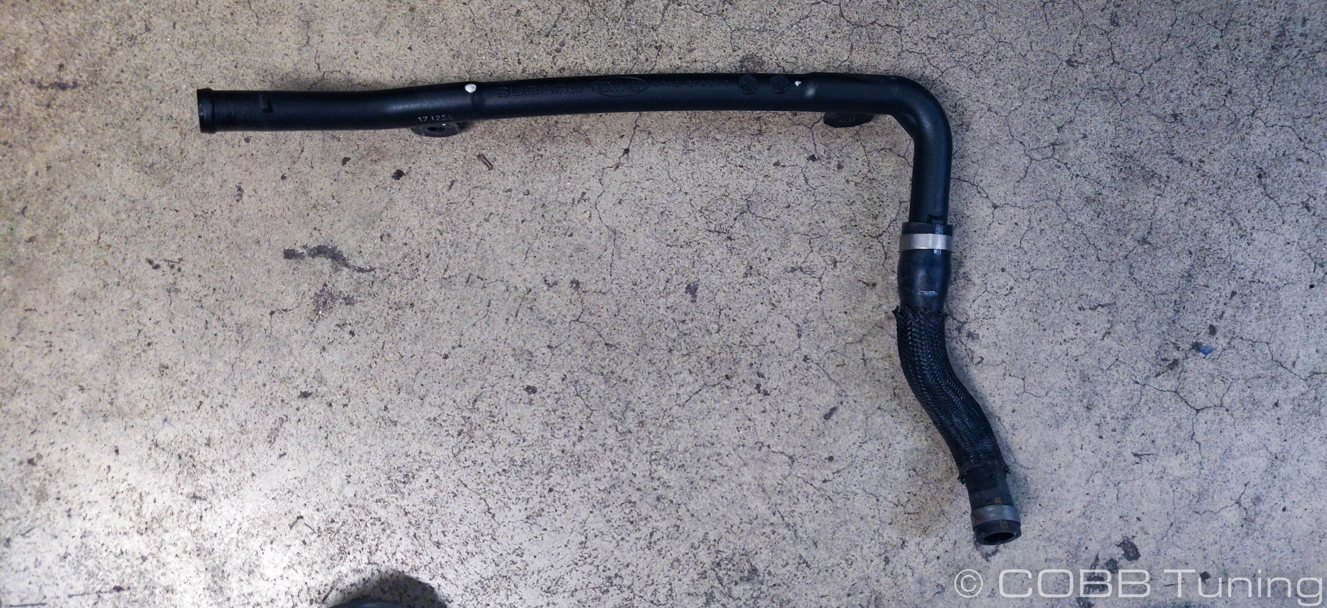
- Locate the 90 degree bent hose coming out of the engine block going to the turbo. This is the coolant line we'll work with.
- Clamp the coolant line with something appropriate for the job.
- Route the two coolant lines along the path you want to run it, it may be worth test fitting the charge pipe back in to make sure it doesn't get in the way.

- The longer hose will connect to the turbo itself. You'll want to move quickly to avoid spilling too much coolant.
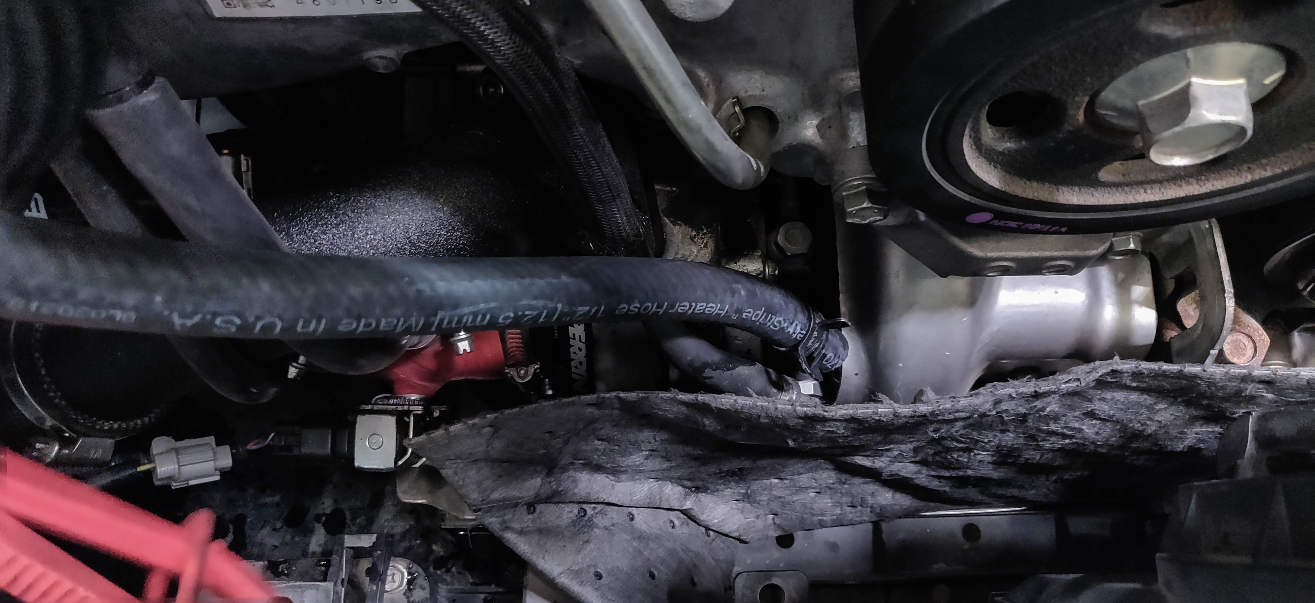
- Take the original line coolant feed lineand rotate it around to the side. You'll want to loosen up the hose clamp to do so.
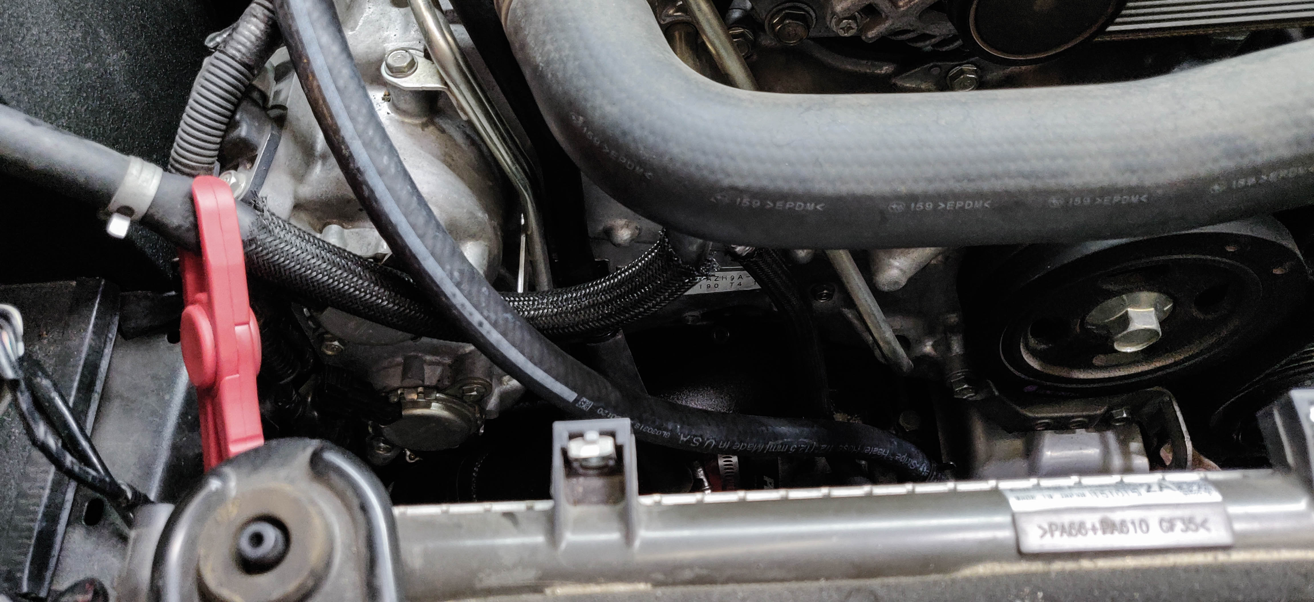
- Route it around to the fitting on the shorter coolant hose from the AOS.

- Once the hose clamps are in place in all spots you can remove the clamp. It's a good idea to double check the hose coming from the block to make sure it isn't crimped where it turns.
Reference Fig.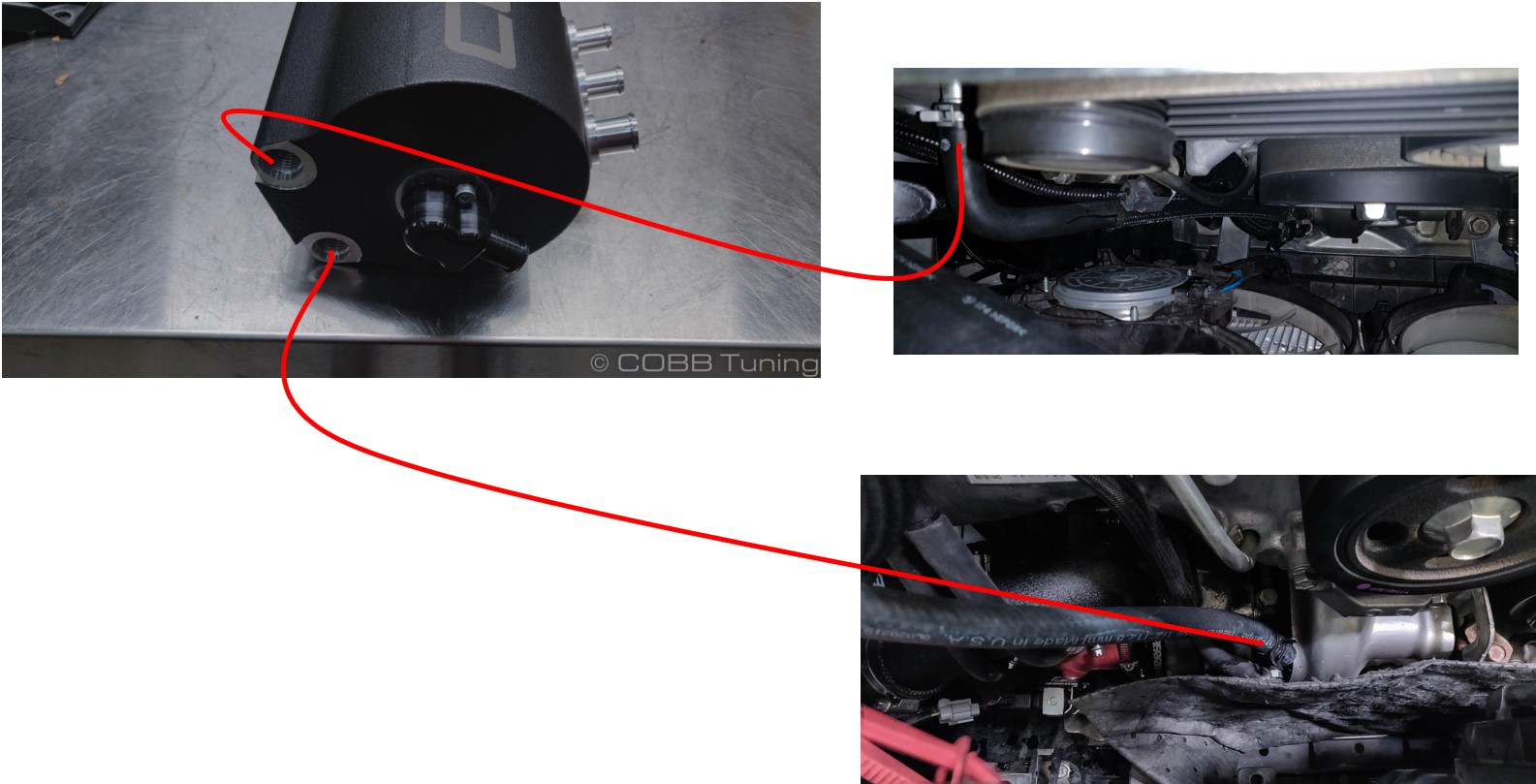
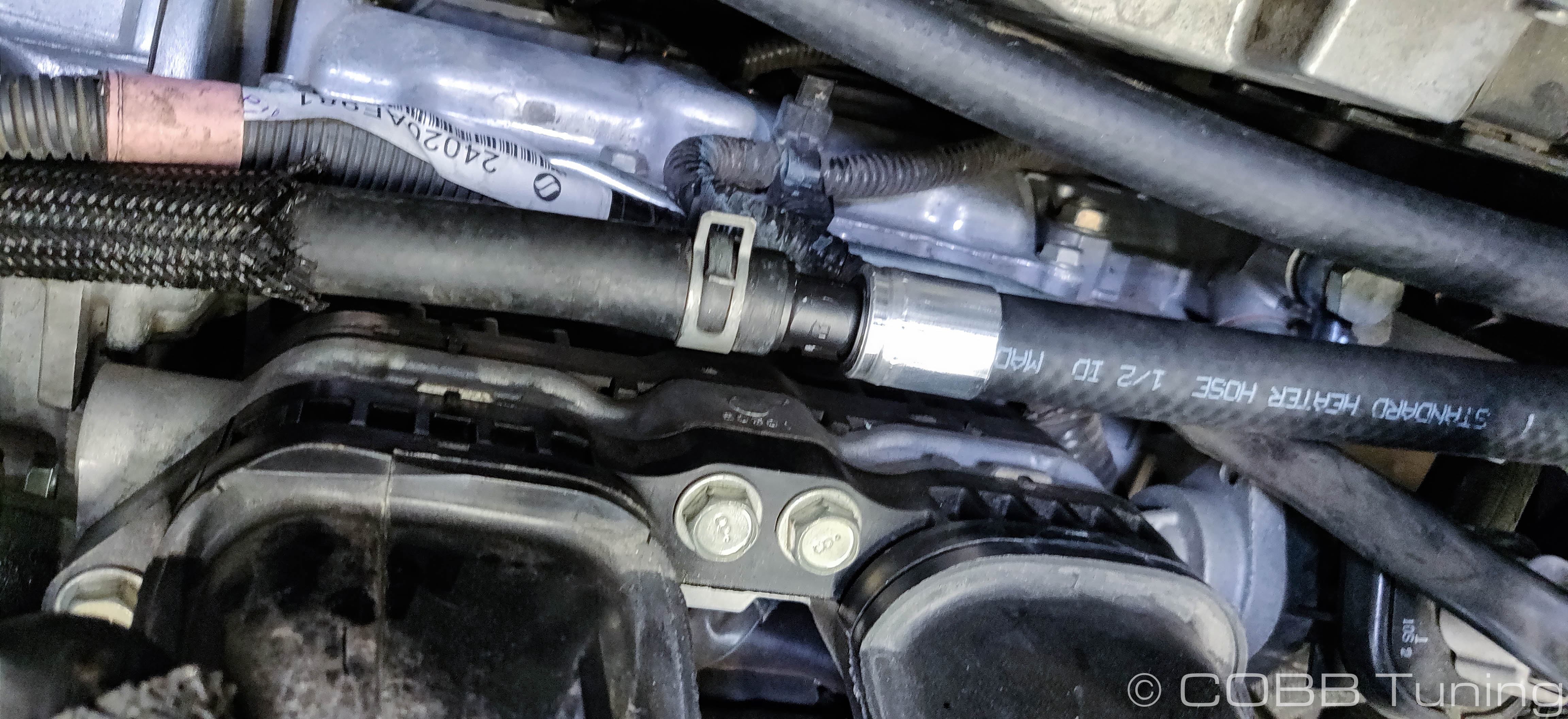
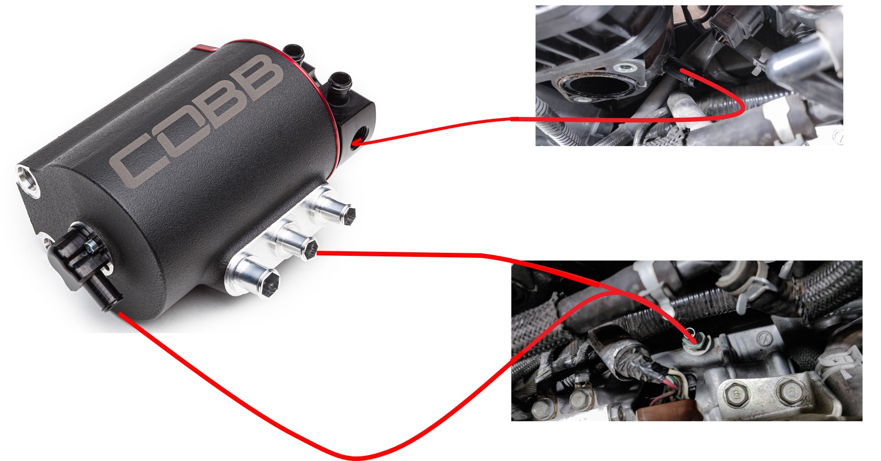
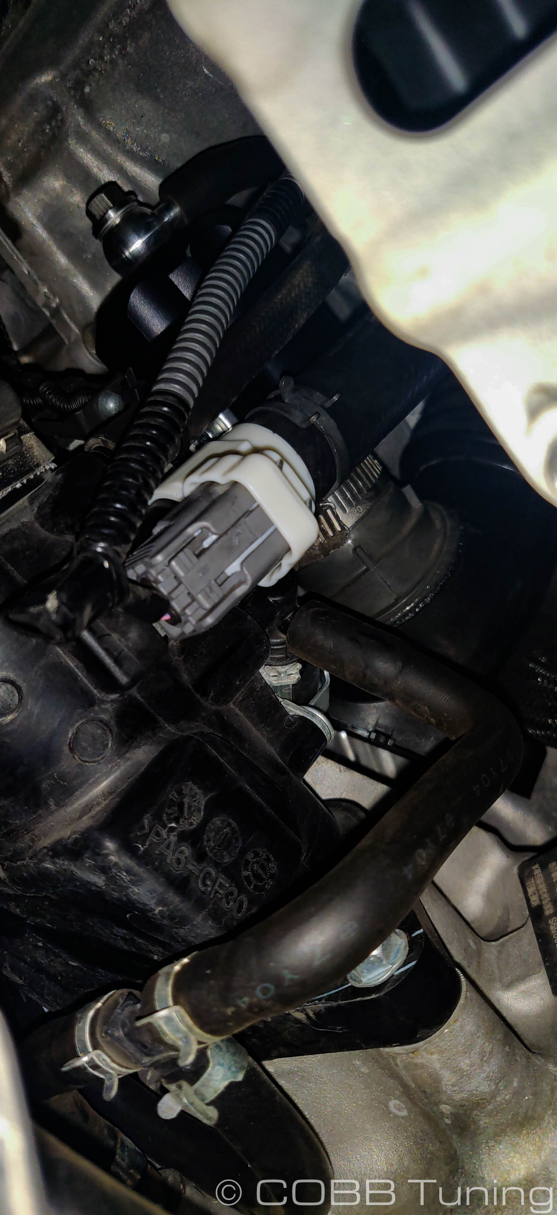
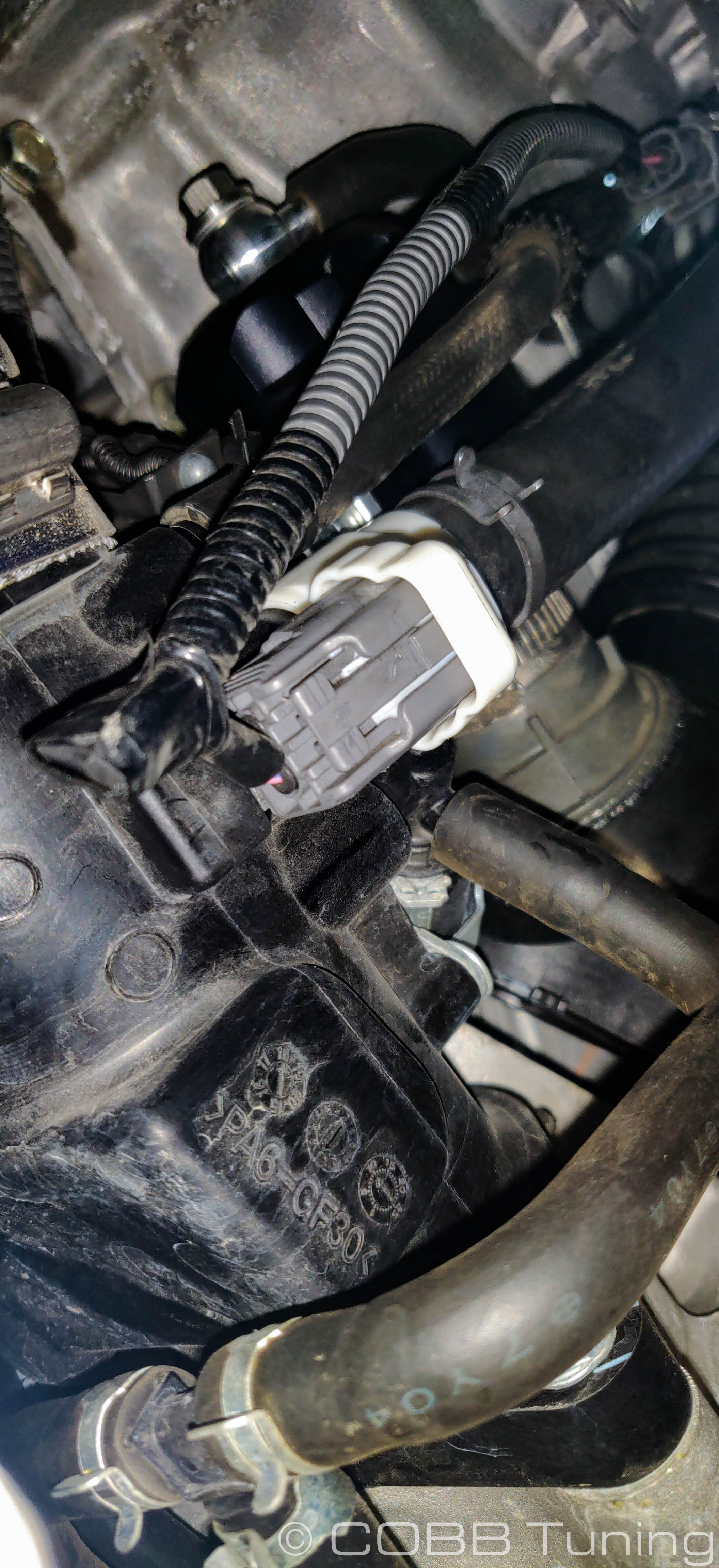
PCV System
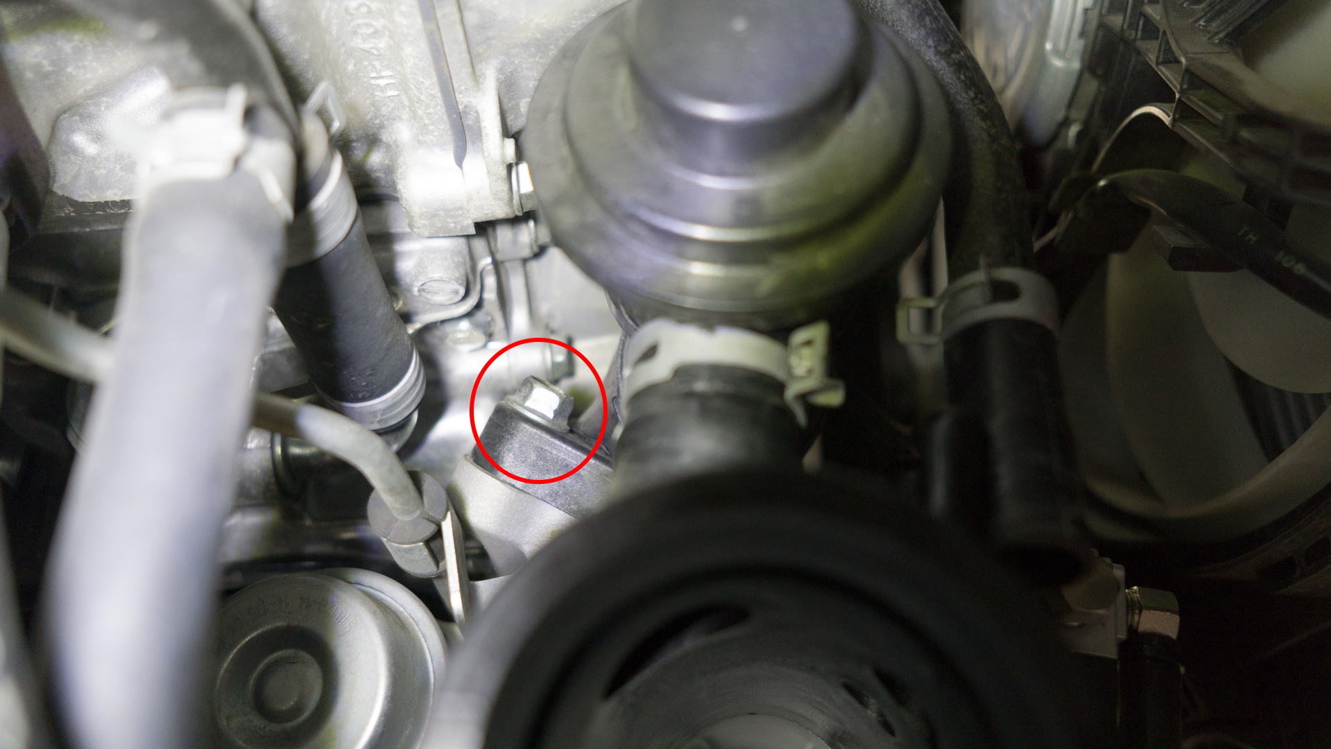
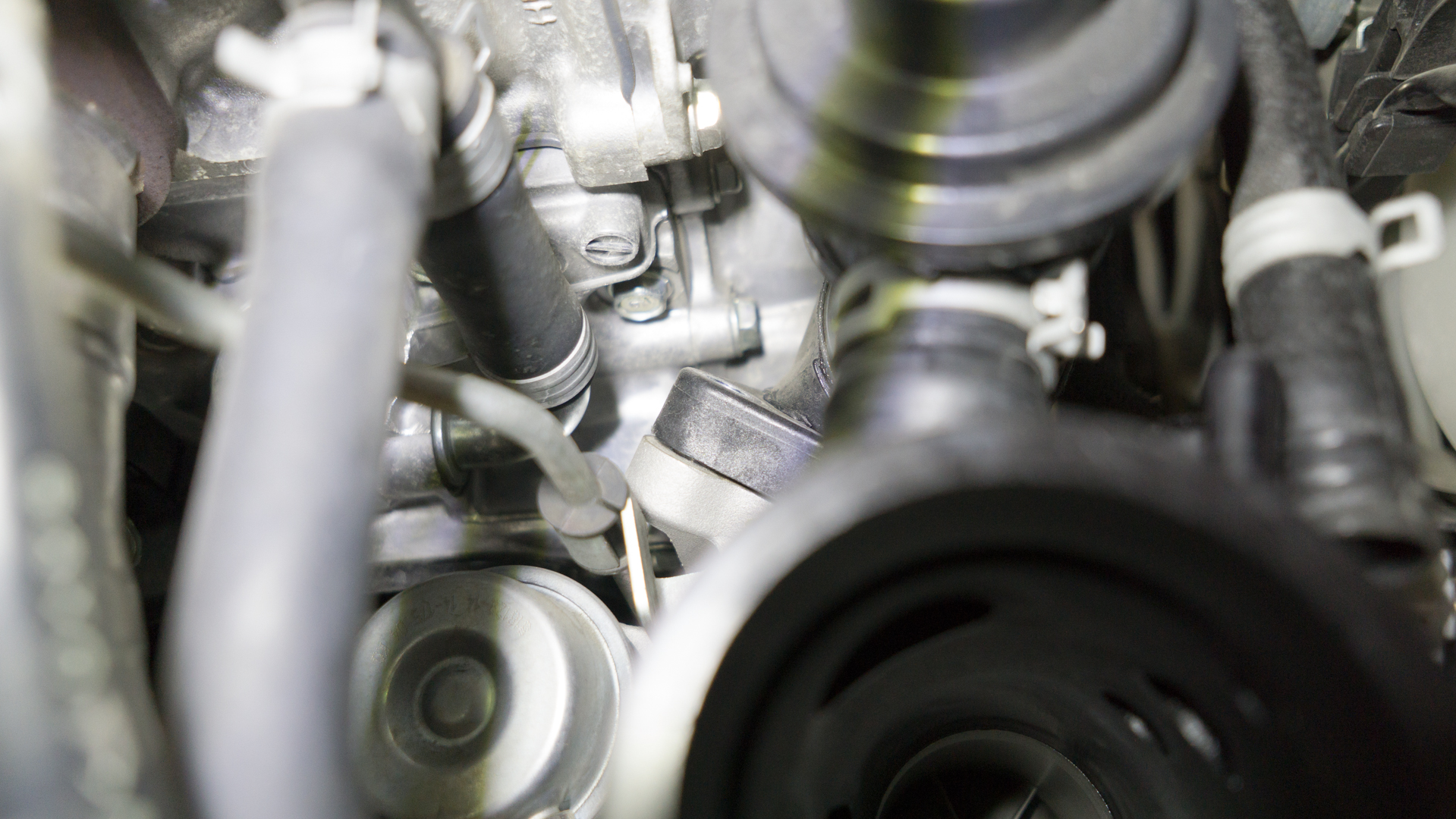
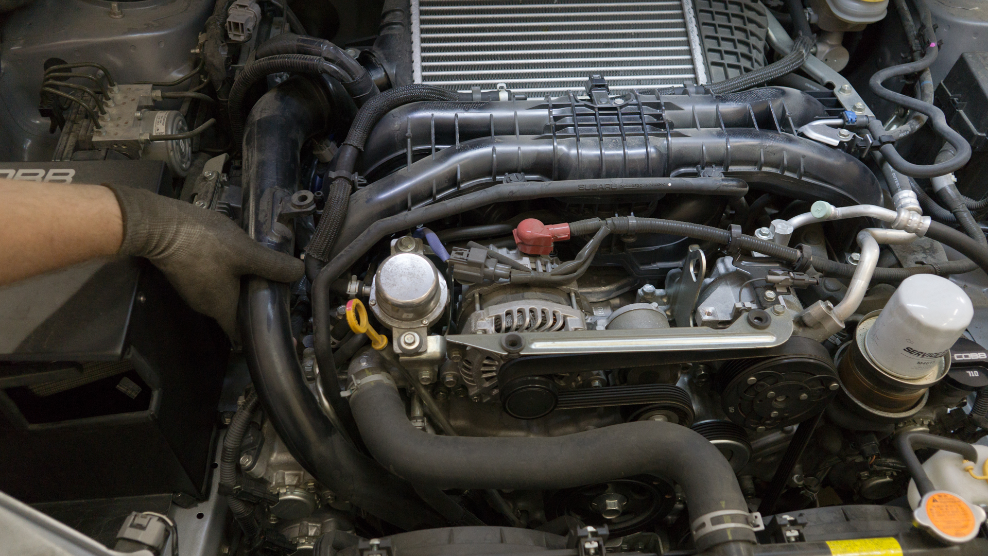
- In order to get a bit more room start by removing the EGR crossover tube by taking the 4 12mm bolts off with your socket. Make sure to inspect the gasket for damage after removal and clean any debris using a light solvent.
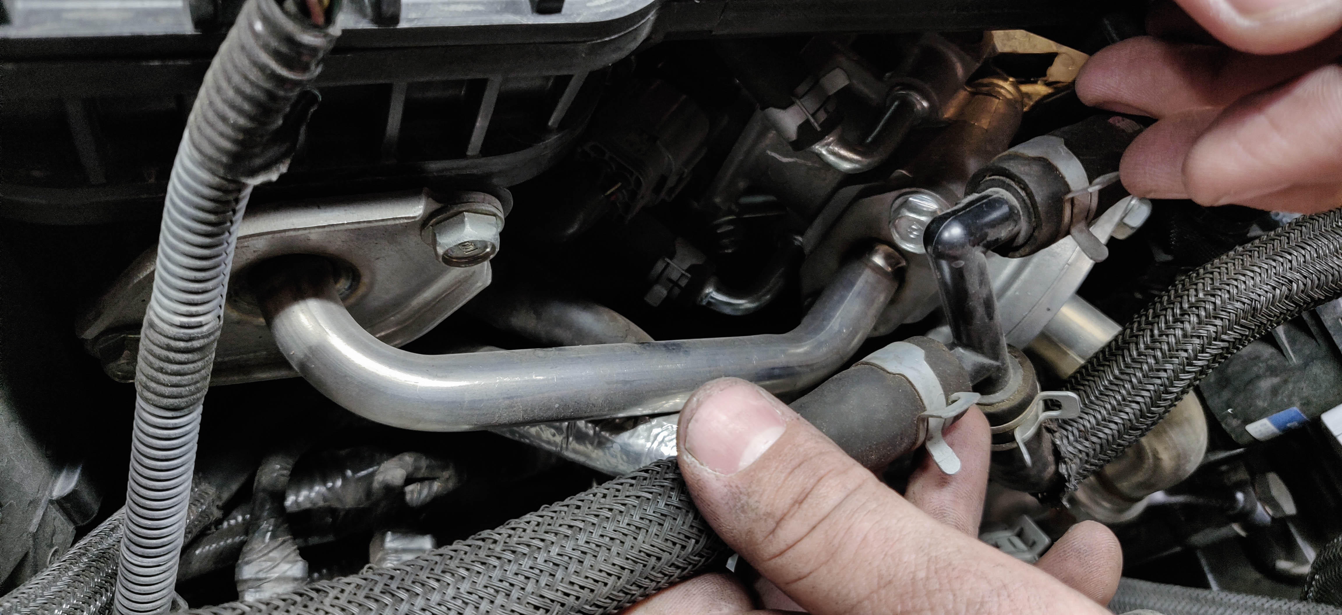

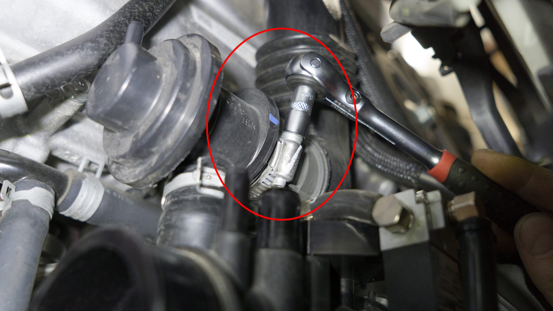
- Remove the hose clamp holding the hose on to the PCV valve on the engine block.
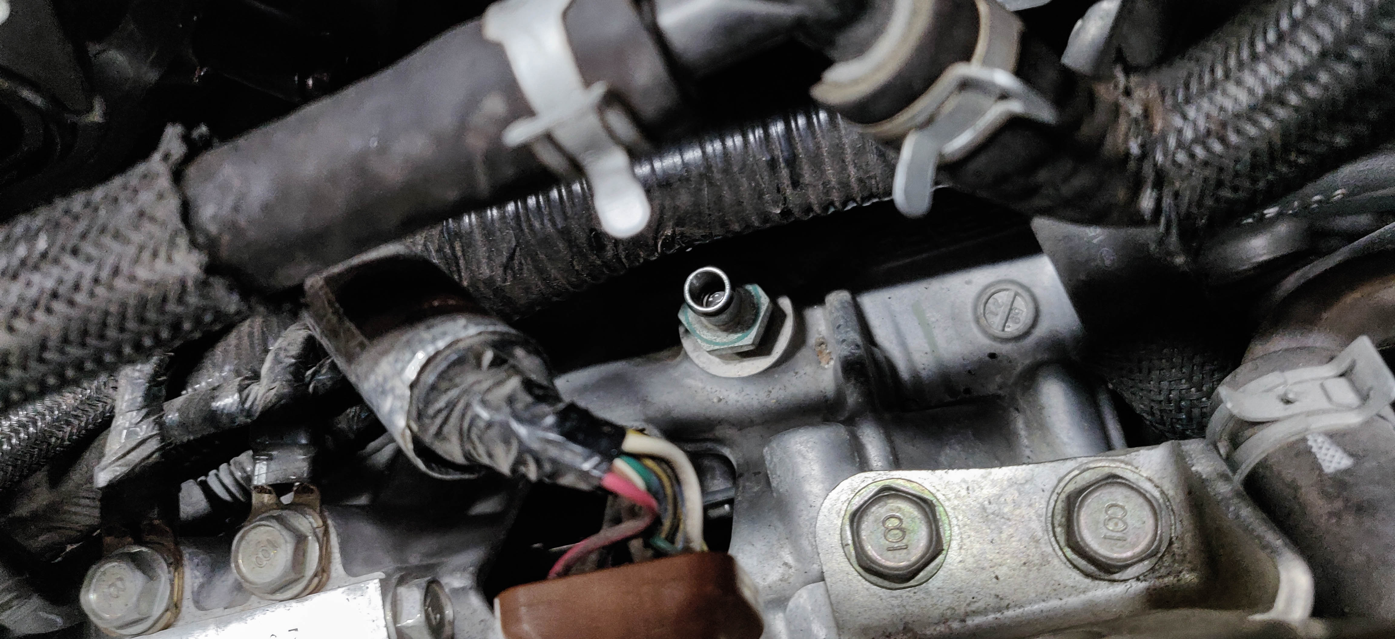
- Remove the valve using a 19mm socket.
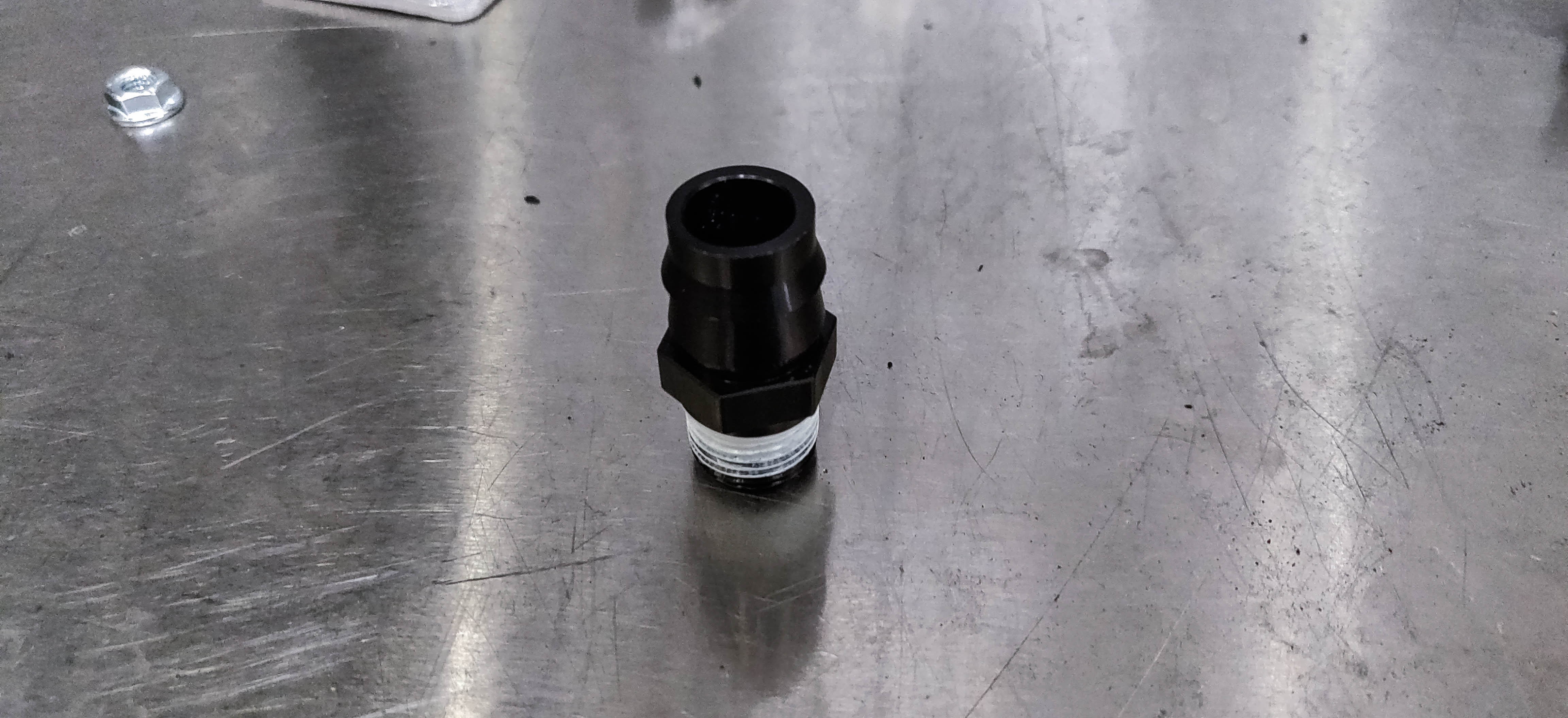
- Install the supplied PCV fitting into the PCV port using your 19mm.
- Install the y-shaped hoses with the large 90 degree bend on the fitting. Secure the fitting with the provided spring clamp
- The shorter of the two hoses will go on the left side and go to the bottom oil drain port of the AOS.
- The Longer hose on the right side will go to the middle port of the AOS and get secured with the provided spring clamp.

- Install the provided cap over the lower AOS port. Secure it with the provided spring clamp.
- With those lower hoses now in place it's a good time to route the wiring and connect it to the power steering control unit. If you need additional slack taking out this electrical tape on the harness can give slightly more freedom.
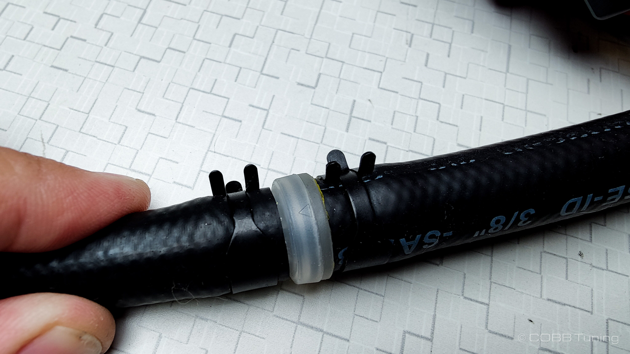
- Install the provided 90 degree fitting into the original PCV hose using the factory spring clamps. Leaving it installed on the manifold. Connect the line coming from the AOS with the in line PCV valve to that 90 degree fitting and secure it with the provided spring clamp.

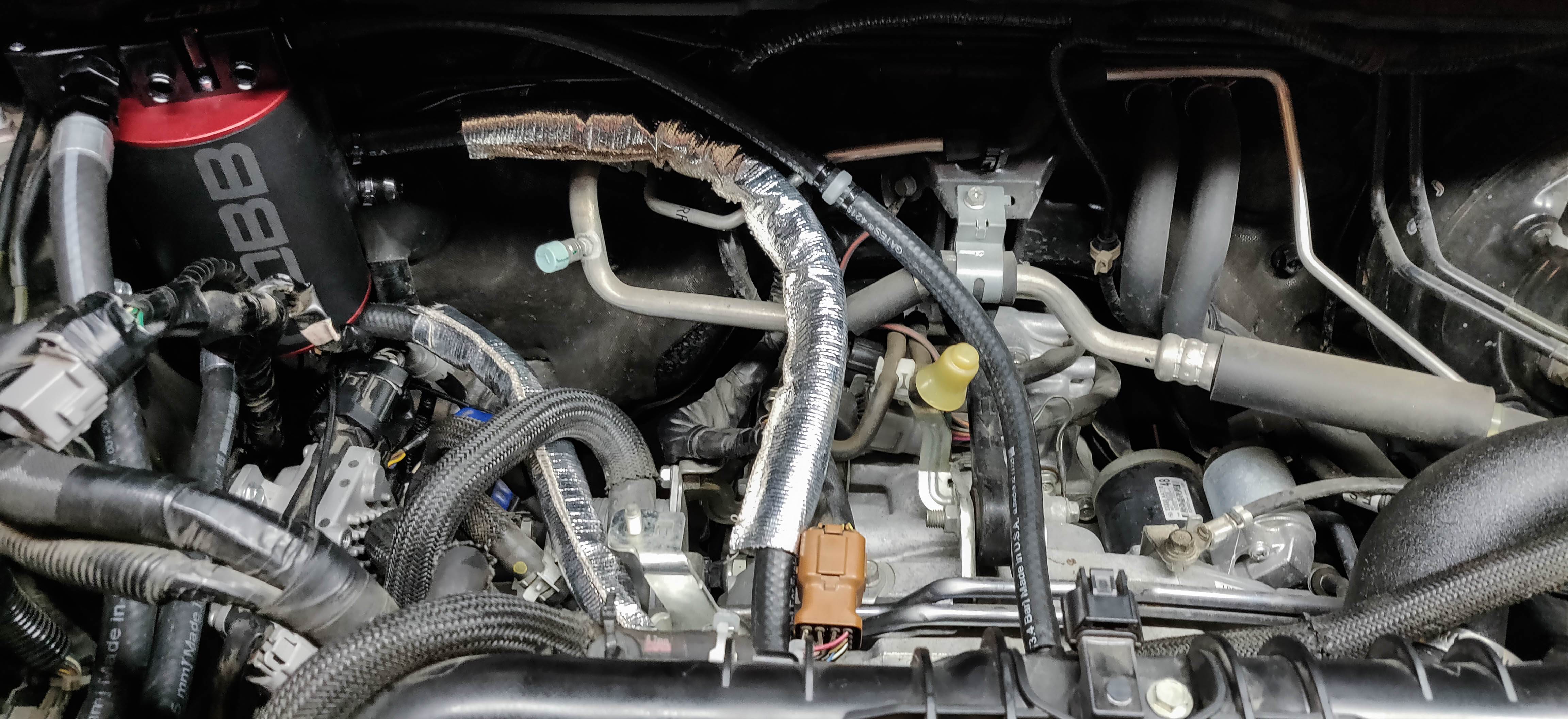
- Reinstall the EGR tube and torque to spec (14 ft lbs). Be careful not to overtorque as it can cause danger to manifold.
Reference Fig.
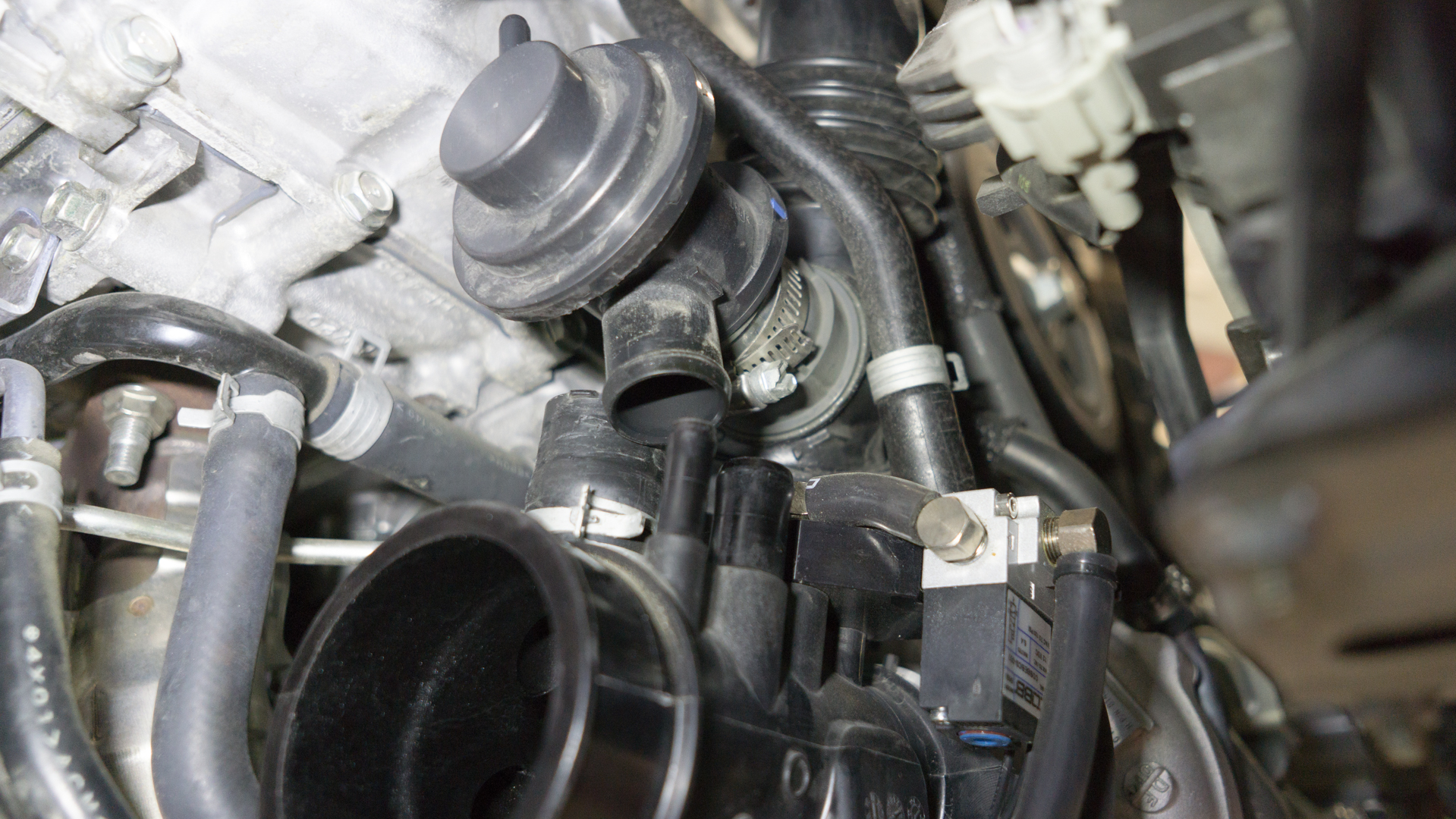
Crank Breather
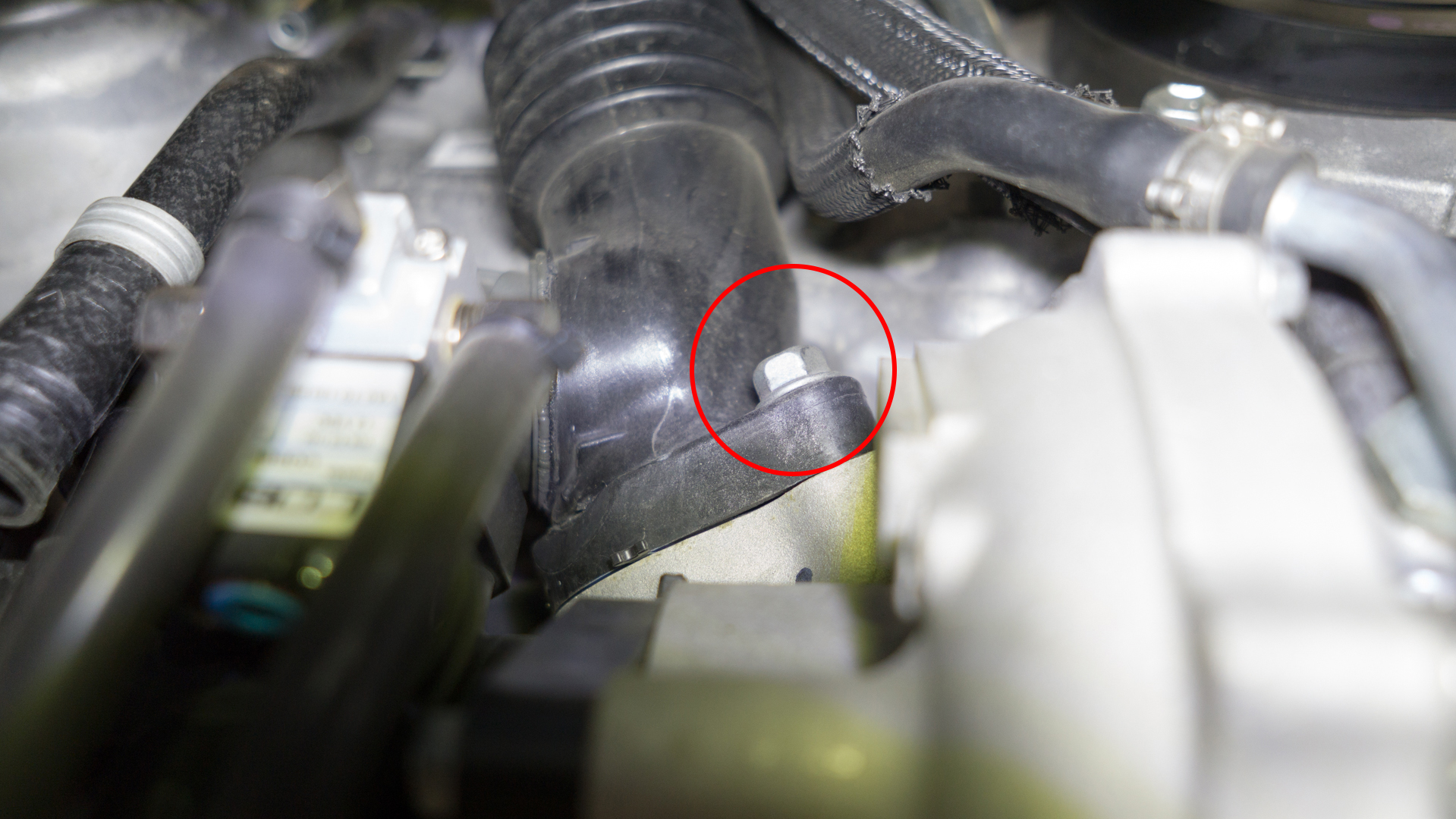
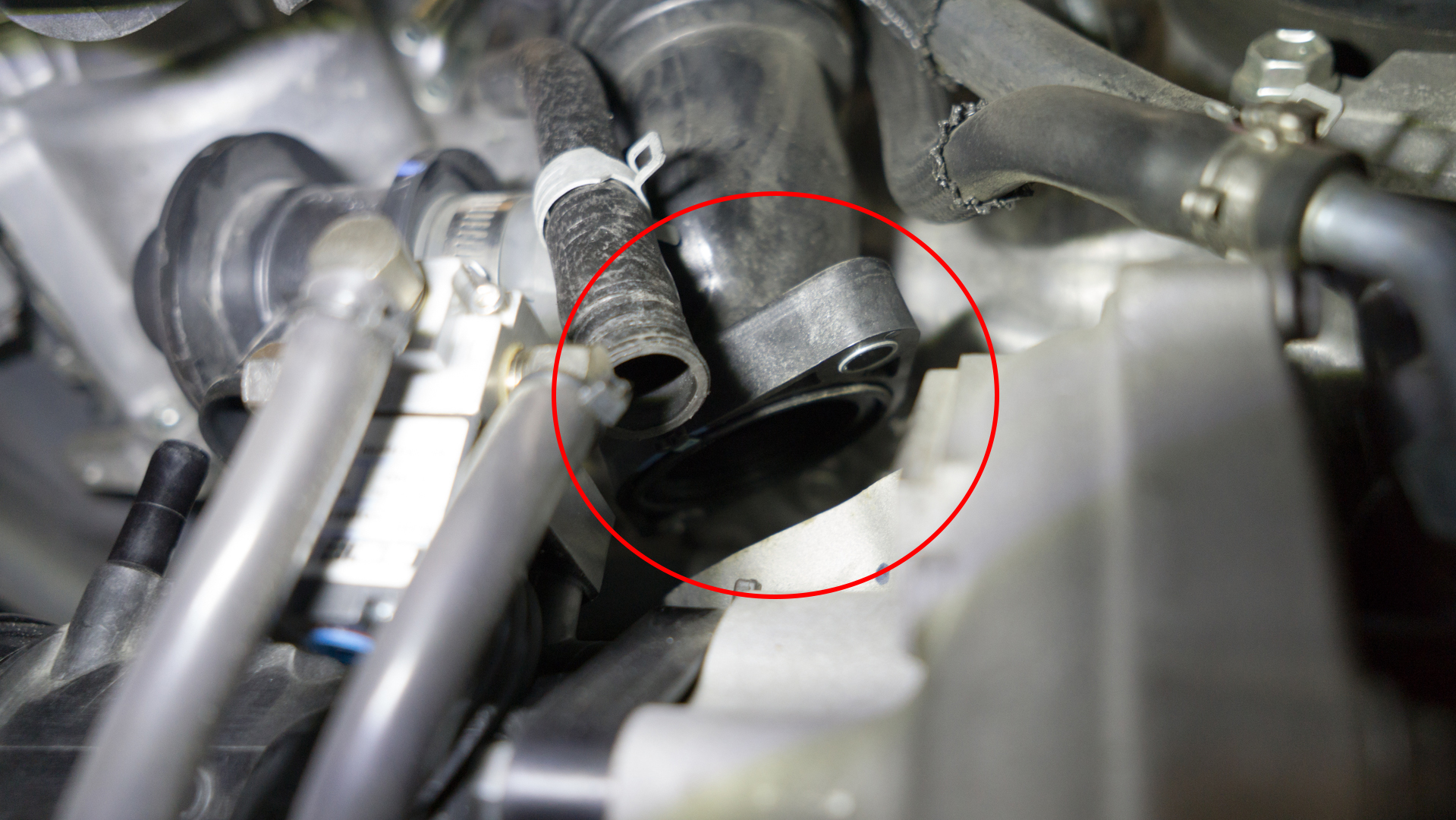
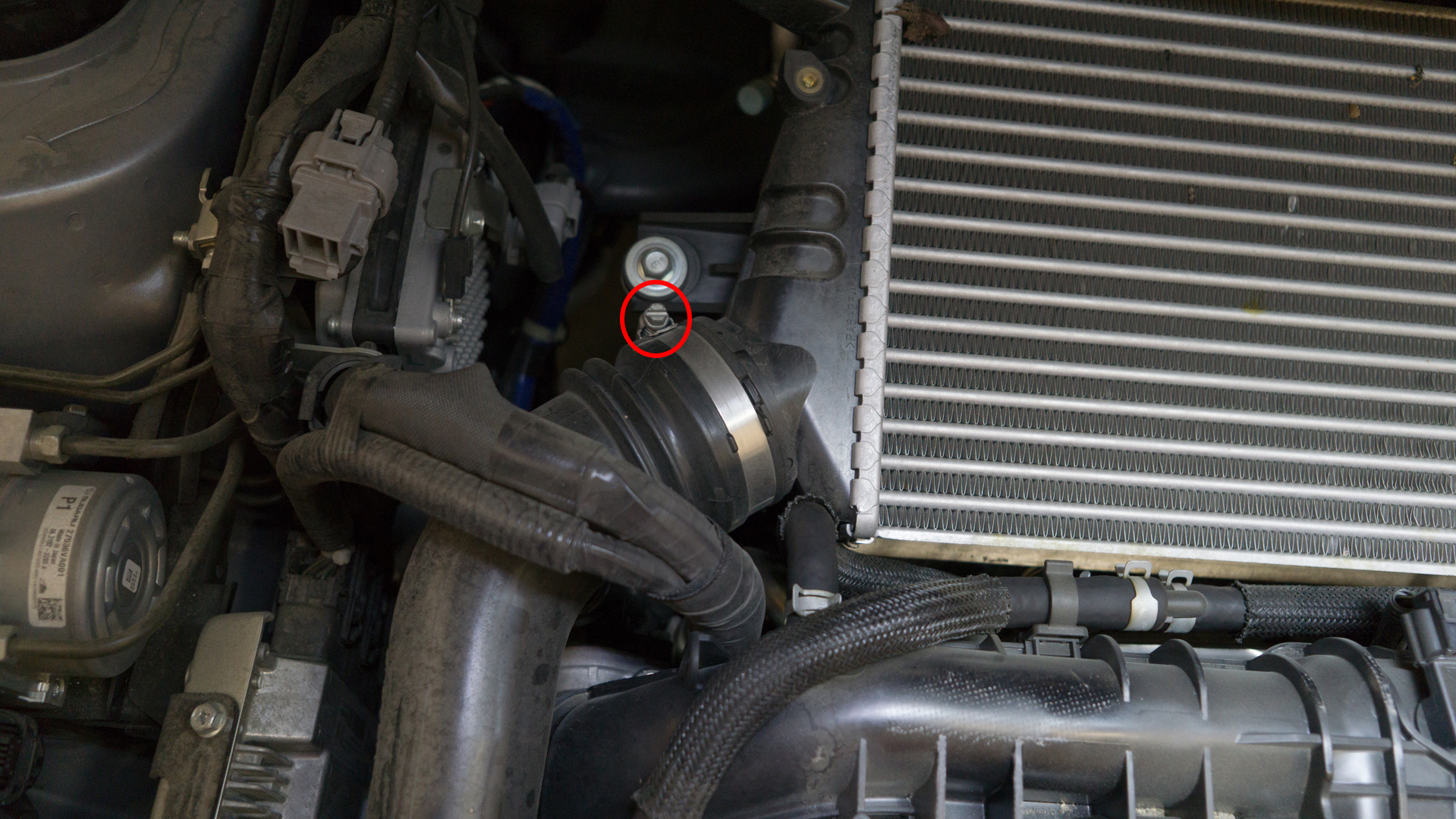
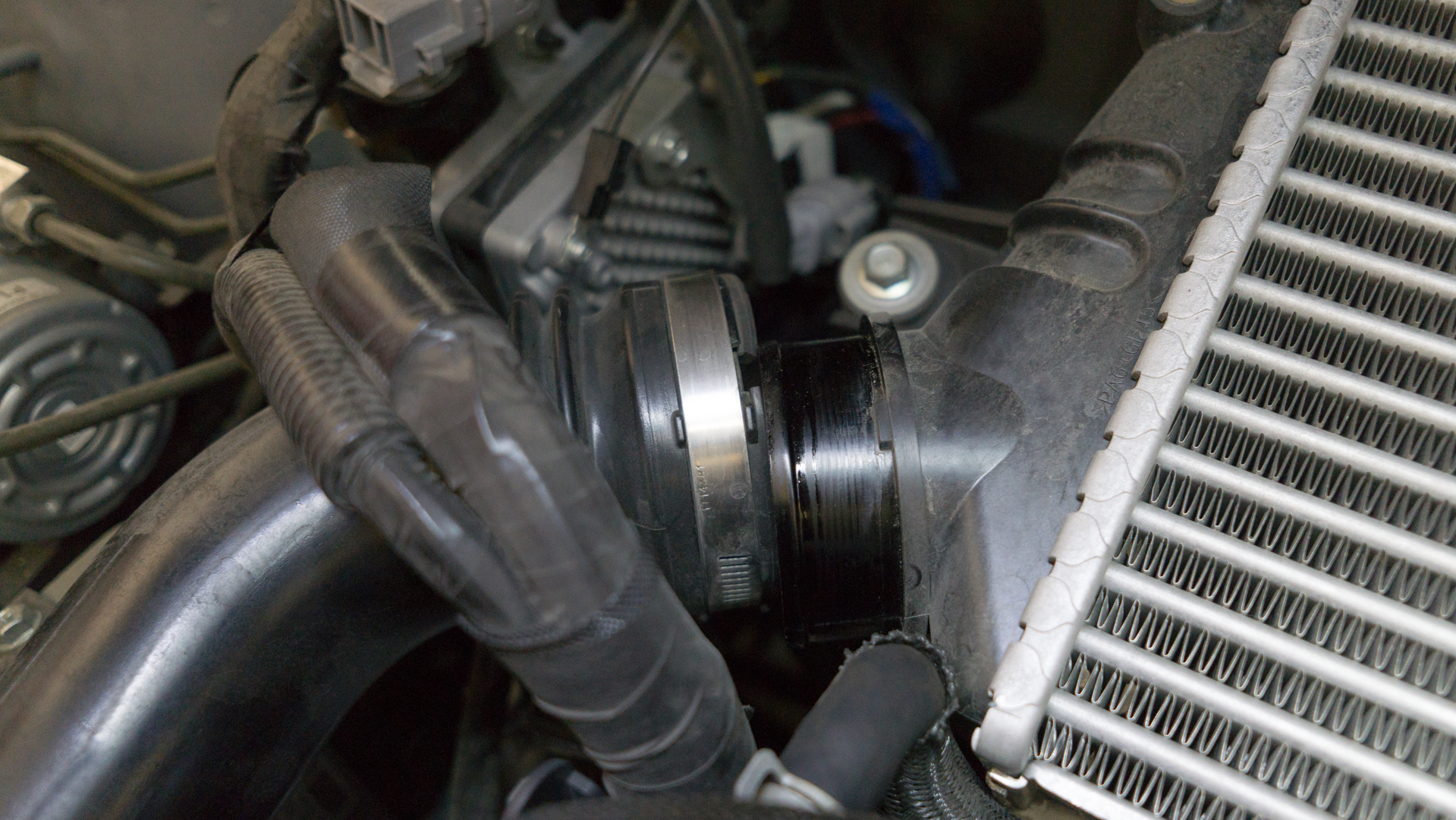
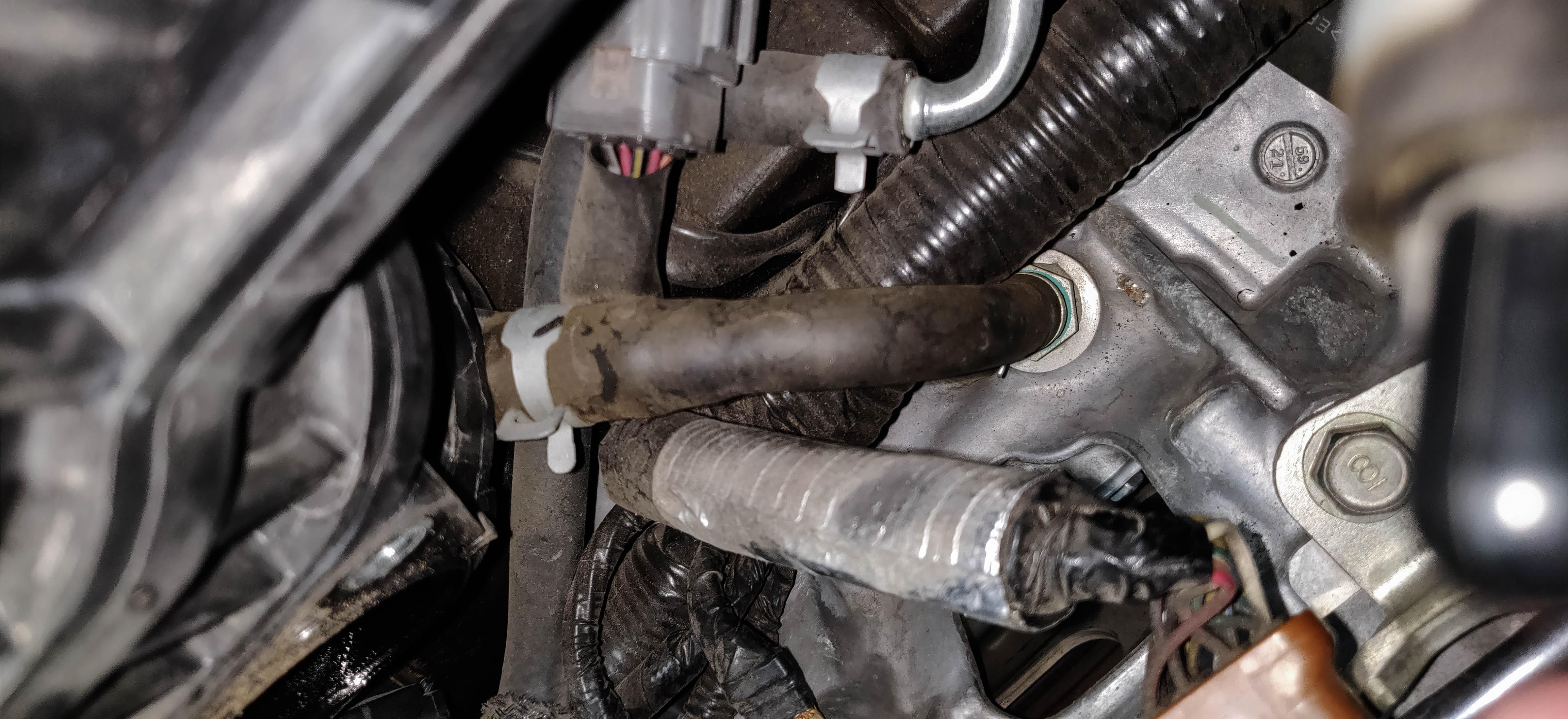
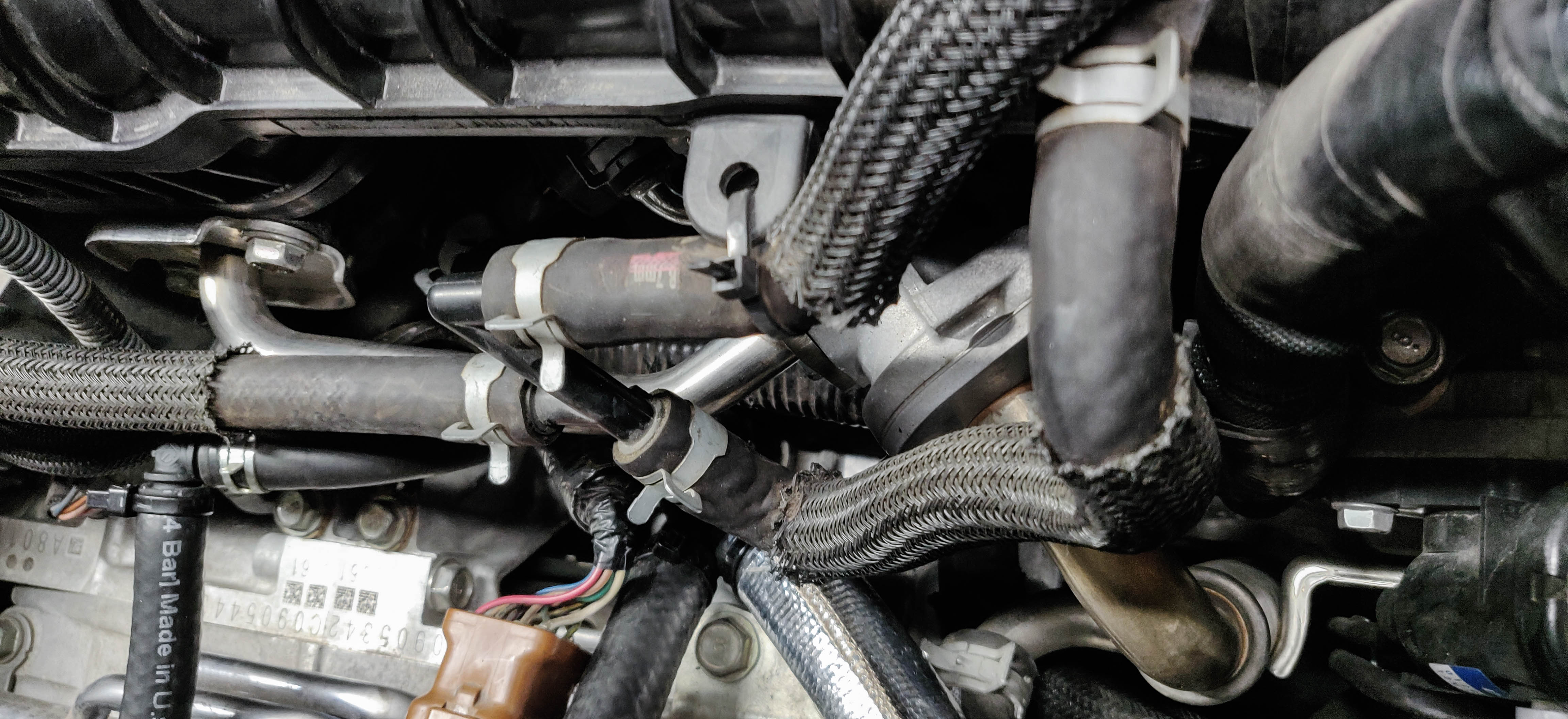
- Undo the connectors holding the crossover tube to the intake manifold by turning the center portion a quarter turn then popping them out with a trim tool.
- Unhook the tube from the turbo inlet side and the connector underneath the AC Compressor. On the 18+ models you'll need to undo the electrical connection and remove the sensor assembly from the inlet with the hose. Removing the hose clamp from the side with the AC is sometimes easier to cut the rubber out from under the permanent metal ring, then remove the ring after the hose is out.
- 18+ only. Remove the white blow-by sensor and install it into the single hose side of the large y-pipe, securing the connection with the provided spring clamp.
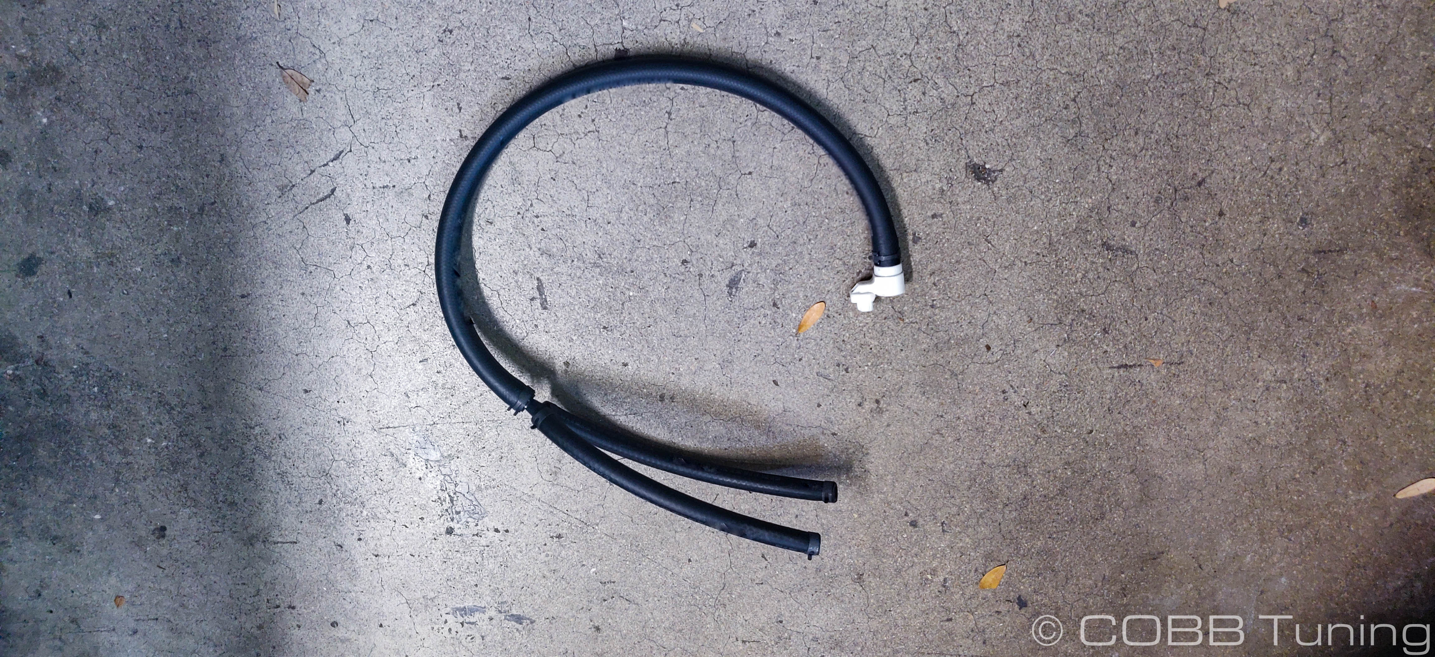
- Install the double sided end of the y-hoses to the top of the AOS using spring clamps to hold them tightly in place
- Now route the other end around and down to the inlet either securing it with a spring clamp, or for models equipped with the blow-by sensor, by reinstalling the sensor onto the inlet with the new hose fitted.
- Take the remaining hose and install it over the fitting behind the AC compressor using a spring clamp.
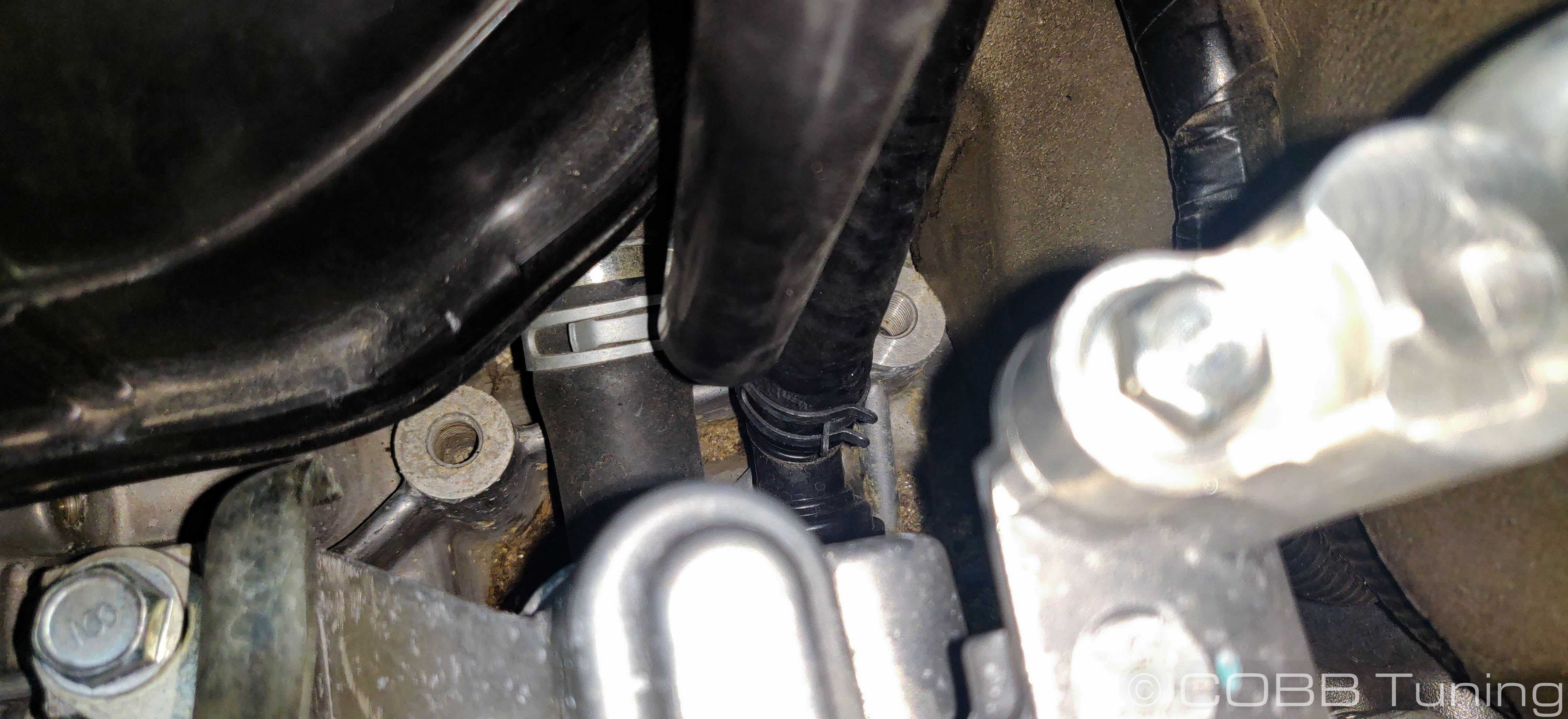
- Route it to the final remaining port (upper side port) and secure it with a hose clamp. For the cleanest look we routed it under the intake manifold.
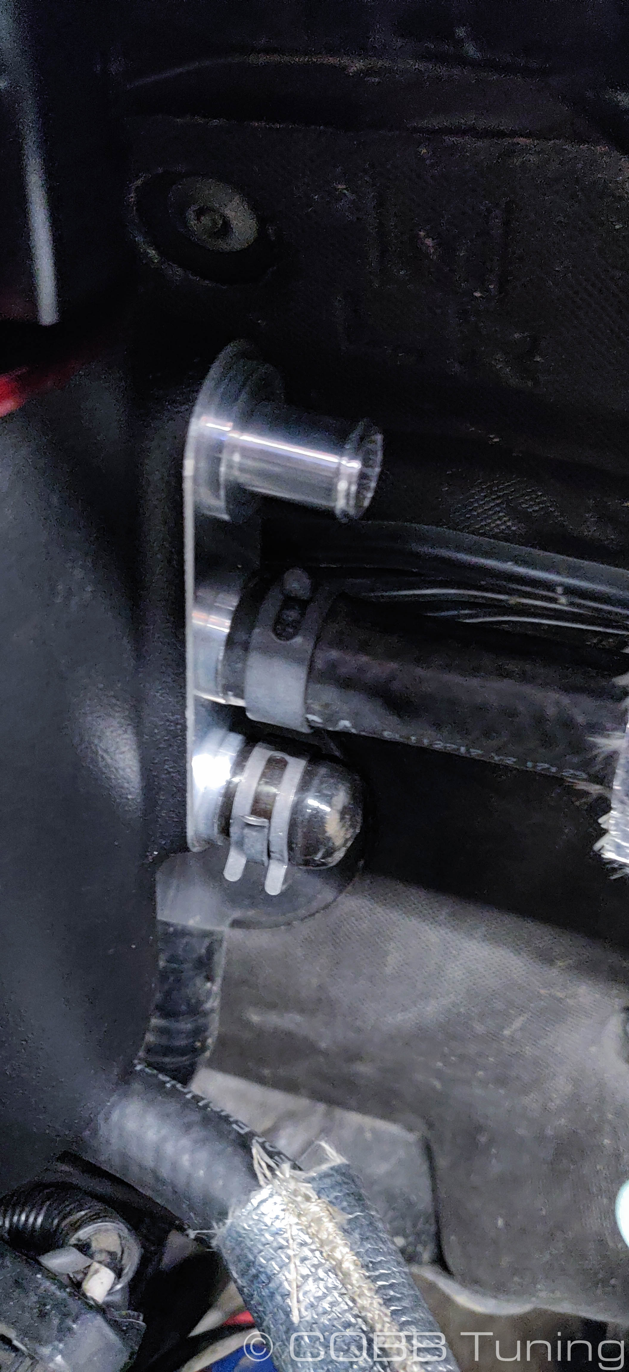
Reference Fig.
COBB AOS Coolant Bleeding Addendum
- Now it's time to bleed the coolant. Ideally you won't have lost a lot of coolant, however this is an important step and can get a little bit time consuming, however any pockets of air can cause issues with overheating or incorrect coolant temperature settings.
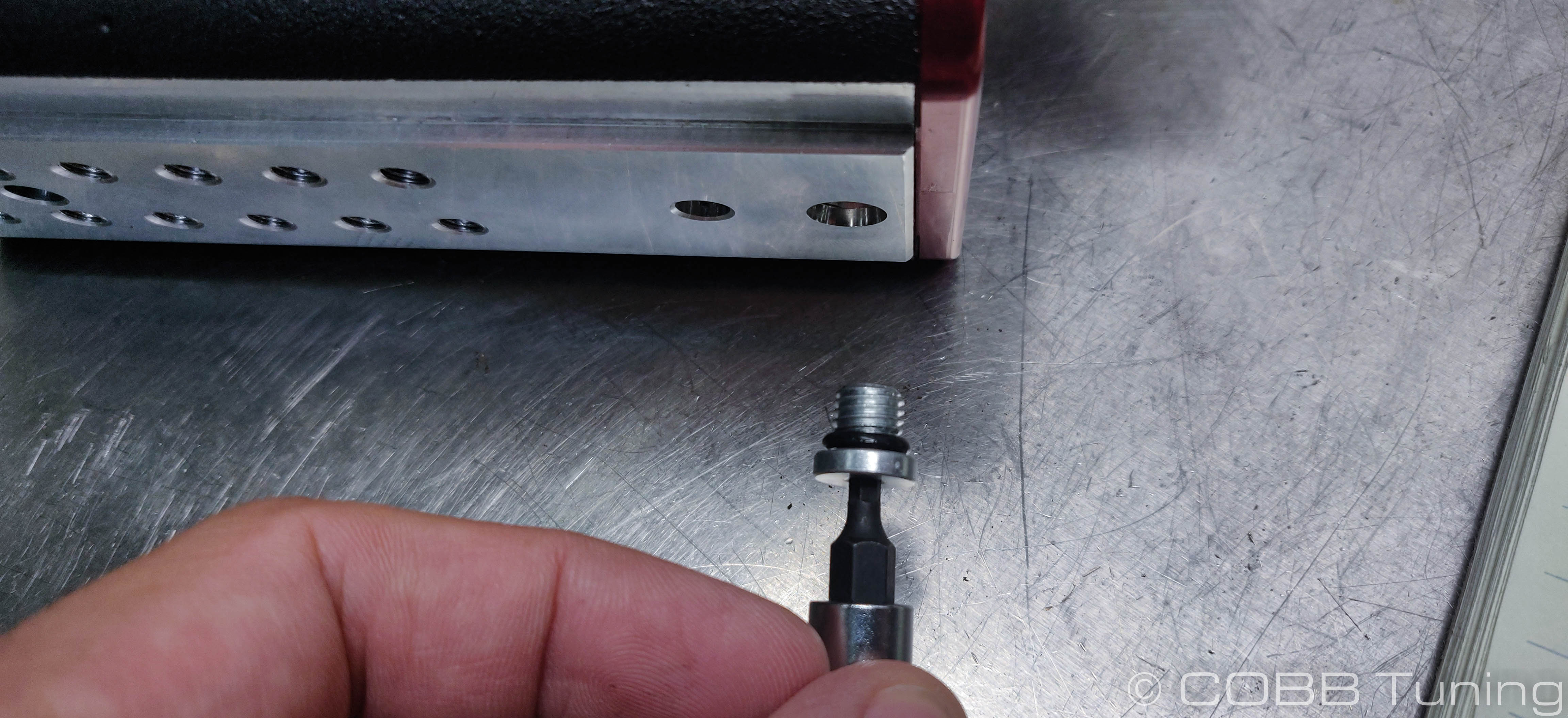
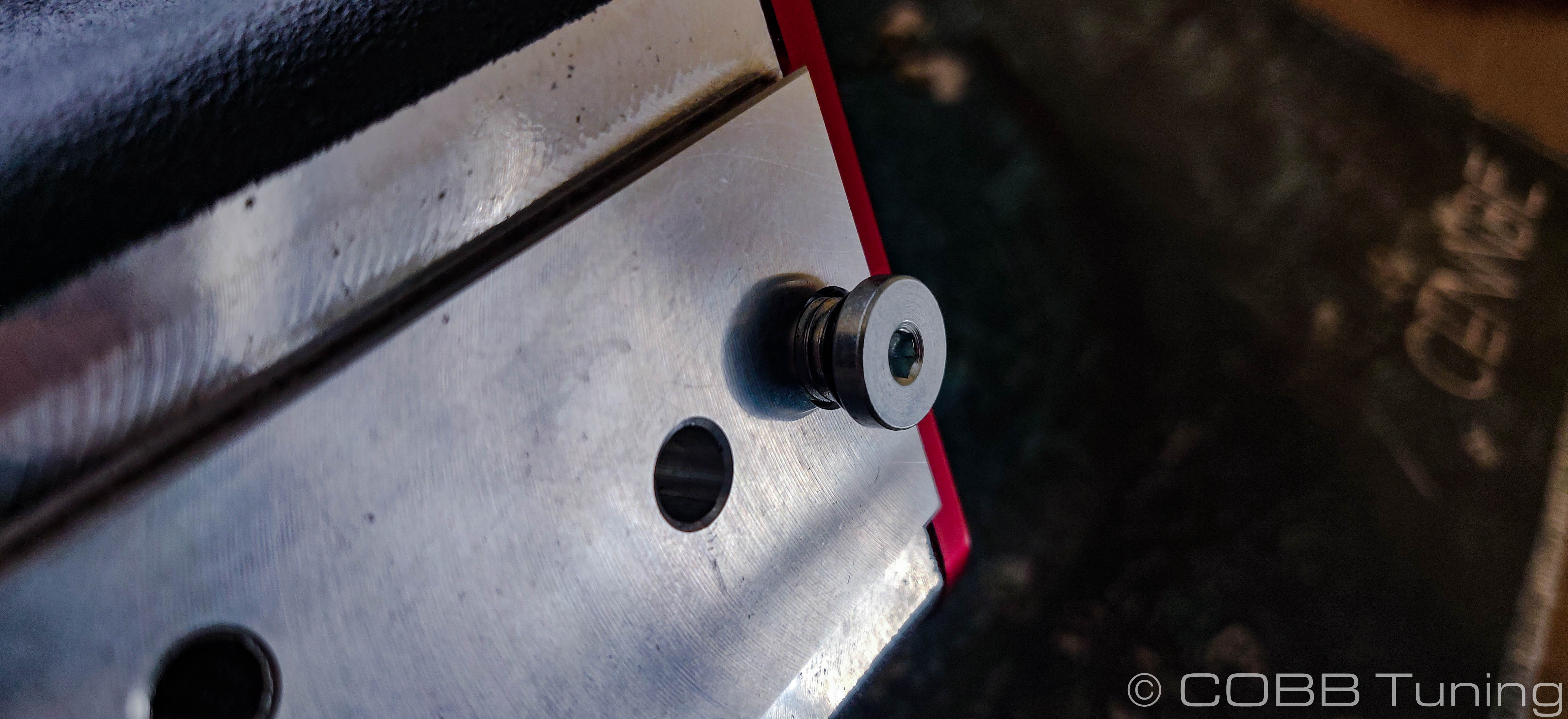
The back of the AOS now comes with this convenient bleeder screw. With the car cold but running, use a 1/8" allen wrench to remove the o-ringed bolt. The fitting should allow coolant and air to come out of the weep hole. Do this until no more air comes out and then re-install the plug hand tight. Over Tightening may cause damage to the sealing o-ring and cause a leak later on.

Optional Full System Coolant Bleeding
- While not necessary bleeding the entire cooling system can ensure no air is still in the system. Using a coolant bleeding funnel like this one can make things a whole lot easier as they come with fittings to mount directly to the cap and allow the system to bleed and fill itself at the same time. (Shown on an STI but the process will be identical using a radiator cap)
Keep in mind that any coolant in the funnel will get just as hot as the rest of the coolant in the engine so use caution to avoid burns.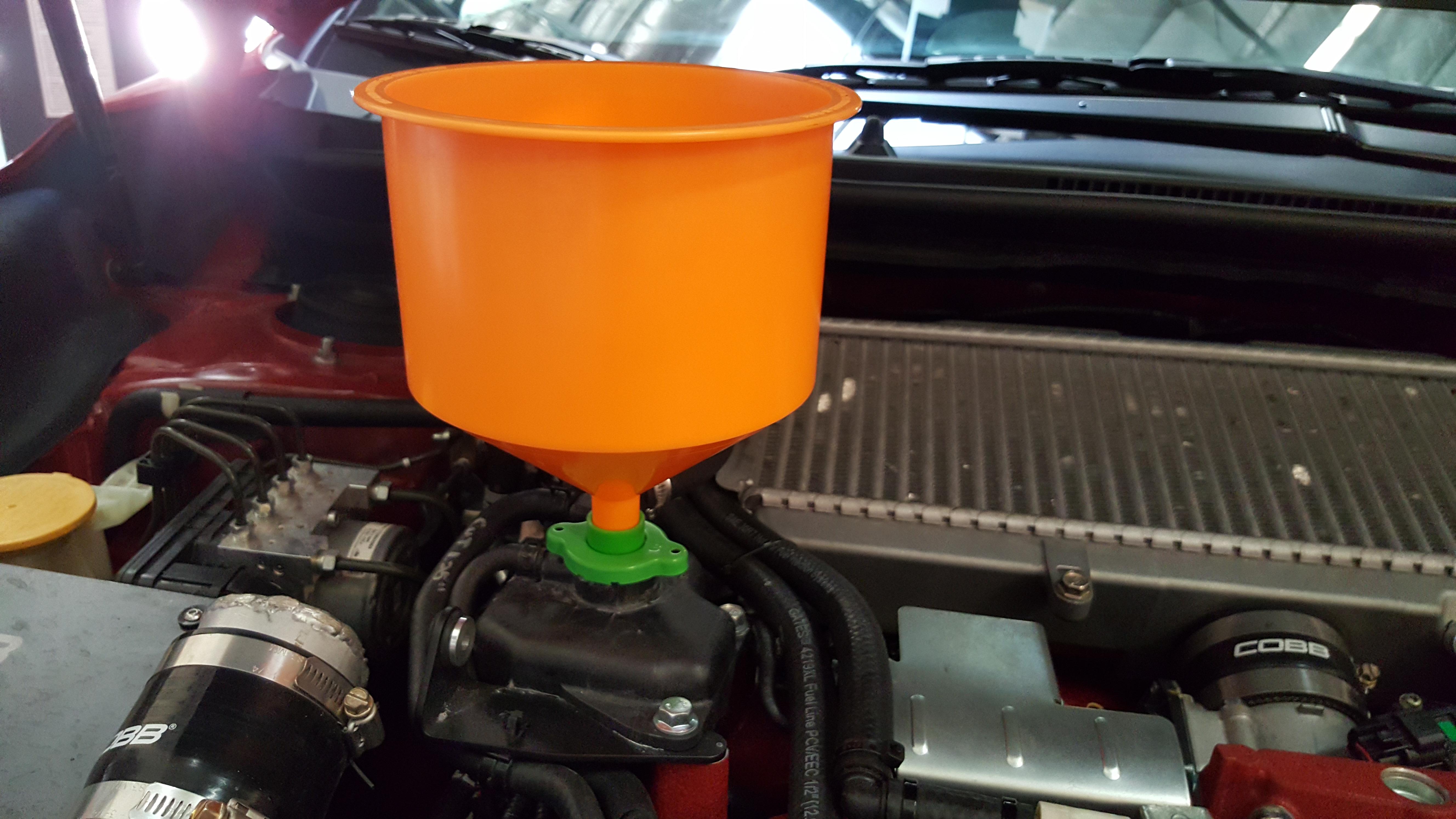
- With the system full turn on the vehicle and crank up the heater all the way. By having the heater on the coolant can circulate through the heater core which will remove air bubbles from that portion of the system. Make sure to keep an eye on your coolant levels at the tank or in the funnel so that the car doesn't add any more bubbles into the system.
- Once the coolant stops bubbling you're all done with the bleeding! This can take a while (it took around 30 minutes on our car). While it's bleeding make sure to keep an eye on the coolant temperature in order to make sure your car isn't overheating and that the fans are cycling on and off properly.
While idling the radiator will got very hot quickly, be careful to avoid burns.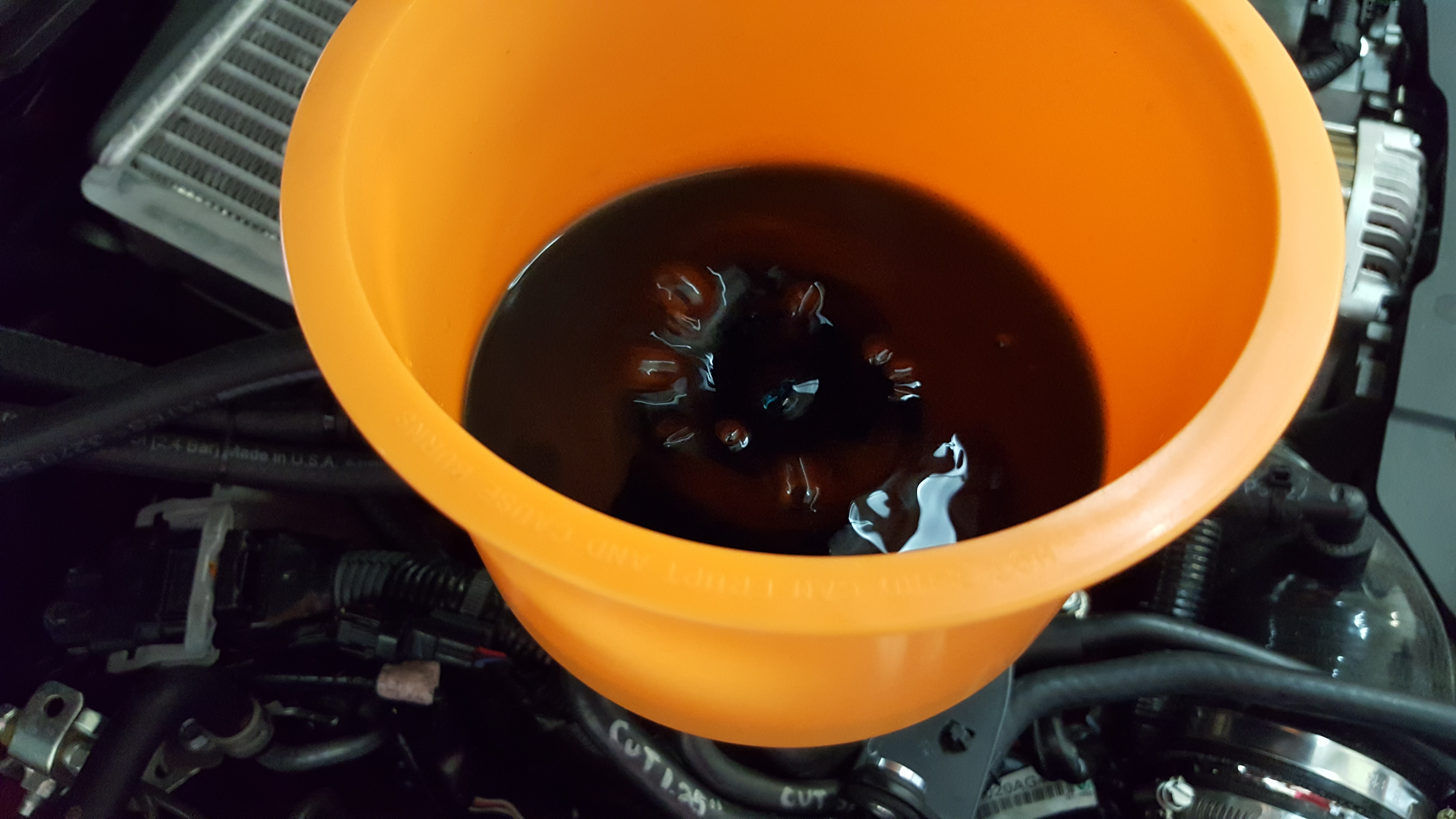
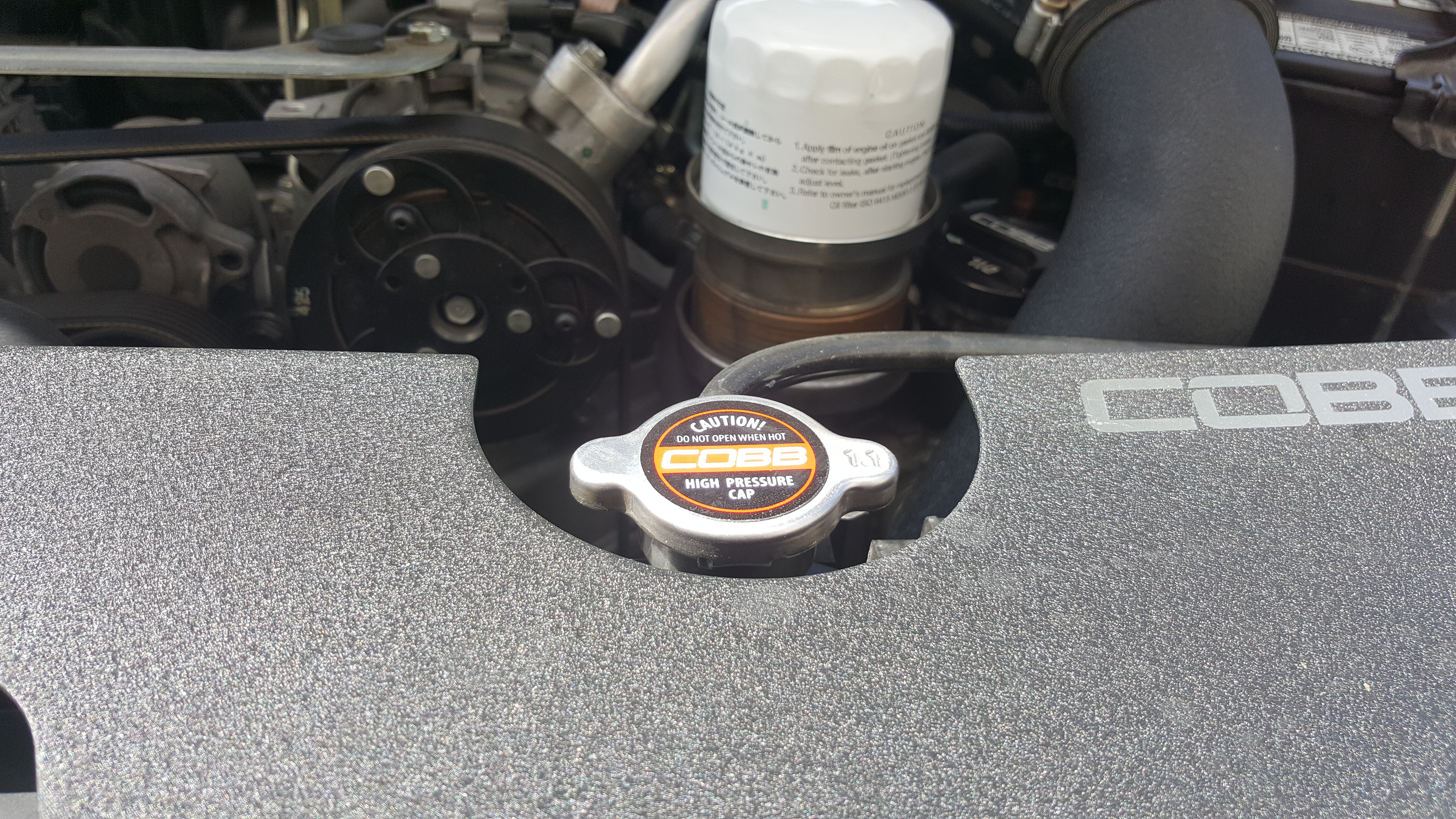
- Place the plug securely down in the funnel and remove it from the car. Put remaining coolant back in the bottle.
- Reinstall the radiator cap.
The back of the AOS now comes with this convenient bleeder screw. With the car cold but running, use a 1/8" allen wrench to remove the o-ringed bolt. The fitting should allow coolant and air to come out of the weep hole. Do this until no more air comes out and then re-install the plug hand tight. Over Tightening may cause damage to the sealing o-ring and cause a leak later on.
- While not necessary bleeding the entire cooling system can ensure no air is still in the system. Using a coolant bleeding funnel like this one can make things a whole lot easier as they come with fittings to mount directly to the cap and allow the system to bleed and fill itself at the same time. (Shown on an STI but the process will be identical using a radiator cap)
Links
COBB Product Install Instructions for Subaru Vehicles
Main Installation Instruction Repository for Subaru Parts
Contact Us:
COBB Customer Support
Web Support and Tech Articles: COBB Tuning Customer Support Center
Email: support@cobbtuning.com
Phone support available 9am to 6pm Monday-Thursday. 9am to 4pm Friday (CST)
866.922.3059
return to www.cobbtuning.com
Related content
Copyright 2025 © COBB Tuning Products LLC. All Rights Reserved. | www.cobbtuning.com