Old Subaru Fuel Pressure Sensor Kit [Discontinued]
These instructions are for the discontinued old kits including the old 312650. For the new ones go HERE
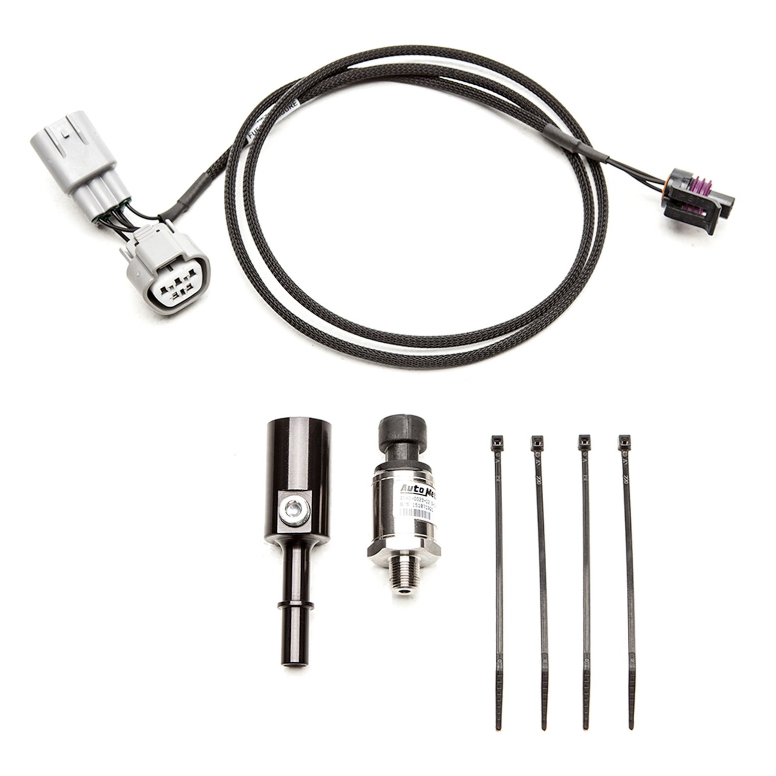
315650 – COBB Fuel Pressure Sensor Kit (5-pin)
Subaru STi 2007 - 2021
Subaru WRX 2008 - 2021
Legacy GT MT 2010 - 2012
Outback XT MT 2010 - 2012
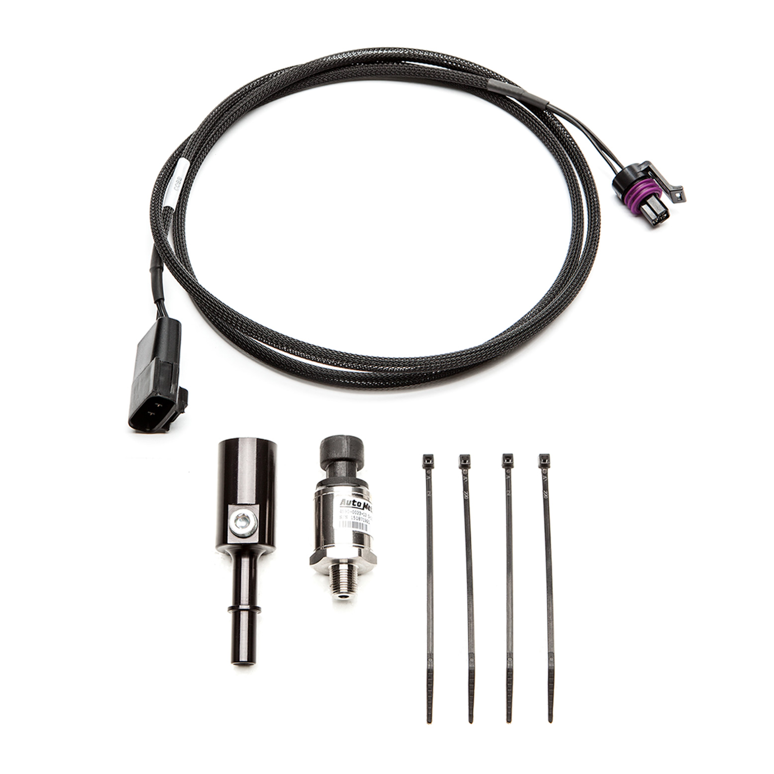
312650 – COBB Fuel Pressure Sensor Kit (3-pin)
Subaru STi 2004-2006, Subaru WRX MT 2006-2007, Forester XT MT 2005
312660 – COBB Fuel Pressure Sensor Kit (3-pin)
Forester XT MT 2006 - 2008
Legacy GT MT 2005 - 2009
Outback XT MT 2005 - 2009
Congratulations on your purchase of the COBB Tuning Fuel Pressure Sensor Kit. The following instructions will assist you through your installation process. Please read them first BEFORE beginning the install and familiarize yourself with the steps and tools needed. If you feel that you cannot properly perform this installation, we HIGHLY recommend you take the vehicle to a qualified and experienced automotive technician.
IMPORTANT! Installing this kit will require custom tuning or utilizing an appropriate Stage Power Package map that allows the TGV to be used for sensor input. Please consult with COBB or an authorized ProTuner in your area.
This Kit is intended to be installed in conjunction with the Cobb Flex Fuel kit for real time Fuel Pressure feedback - a safety feature required for OTS maps. Please refer to the Flex Fuel Kit page for instructions on removing the fuel lines.
Part List
- 1 x Fuel Pressure Sensor
- 1 x COBB 1/8 - 10mm Billet Fuel Line Adapter
- 1 x TGV Harness
- 4 x Zip Ties
- 1 x Loctite 545 thread sealant
Tools Needed
- 5/16" or 8mm Fuel Line Disconnect Tool (Available at Professional Tool Sources)
- 1/2" 7/8" Deep Socket
- 1/2" Ratcheting Wrench
- 3/16" Hex key
- Flat Head Screwdriver
- Diagonal Cutters or Scissors; (Hose Cutting tools suggested for straightest cuts)
- Safety Glasses
- Rags
- Silicone Spray or Similar
Installation
First off you'll need to decide where you're going to install the sensor, use the table below to find the best place for your sensor. While it can work in other positions these are where we typically recommend they get installed. 315650, 312660 Where to install the sensor Installs straight onto the provided AN adapter for the fuel rails While it can be installed onto the flex fuel sensor this can cause problems with the length of the pre-made lines and cause things not to fit or rub in places so if you choose to install it in this way, make sure everything fits appropriately. 312650 Installs straight onto the provided AN adapter for the fuel rails While it can be installed onto the flex fuel sensor this can cause problems with the length of the pre-made lines and cause things not to fit or rub in places so if you choose to install it in this way, make sure everything fits appropriately.Fuel Pressure Sensor by Itself Flex Fuel Fuel Rails Flex Fuel and Fuel Rails Install on the 5/16" feed line using the 300100 adapter Can be installed to the 5/16" feed line using the 300100 5/16 to quick connect adapter Installs straight onto the provided AN adapter for the fuel rails
2005-2006 non-quick connect fuel line carsRequires the 3/8" fitting 300110 straight onto the feed line Installs to the flex fuel sensor directly using the 300110 3/8 to quick connect adapter Installs straight onto the provided AN adapter for the fuel rails
Installation Prep
Important! Before removing your fuel line, make sure to discharge existing fuel pressure from the system. Failure to do so can result in property damage, fire, and severe burns!
- With your car parked in a flat, level area pop the hood and remove the fuel pump fuse.
- Go ahead and start the car up and let it idle.
- Continue to let the car idle until it stumbles and dies.
- Turn the key to the "OFF" position and remove them from the ignition
- At this point, the fuel system has been mostly discharged. You may want to wait a few minutes for any potential pressure remaining in the system to dissipate before proceeding.
- Disconnect the negative terminal on the battery
Installation Using Billet Adapter
Using Billet Adapter
The COBB Fuel Pressure Sensor installs in the lines between the intake manifold side fuel line connector and the regulator. In our example we're still using the factory regulator so we'll be installing the sensor on our feed line. Our Flex Fuel Sensor and/or Fuel Pressure sensor do not restrict fuel flow and will not cause any hindrances. It's also mandatory that you install either sensor pre-regulator, regardless of application, to ensure accurate readings. The flow of fuel is as such:
- Fuel tank → firewall side fuel hardline connection point → (INSTALL SENSOR(S) HERE) → intake manifold side fuel hardline connection point → fuel rail (OEM fuel pressure regulator) → combustion → manifold side fuel hardline connection point → firewall side fuel hardline connection point → fuel tank
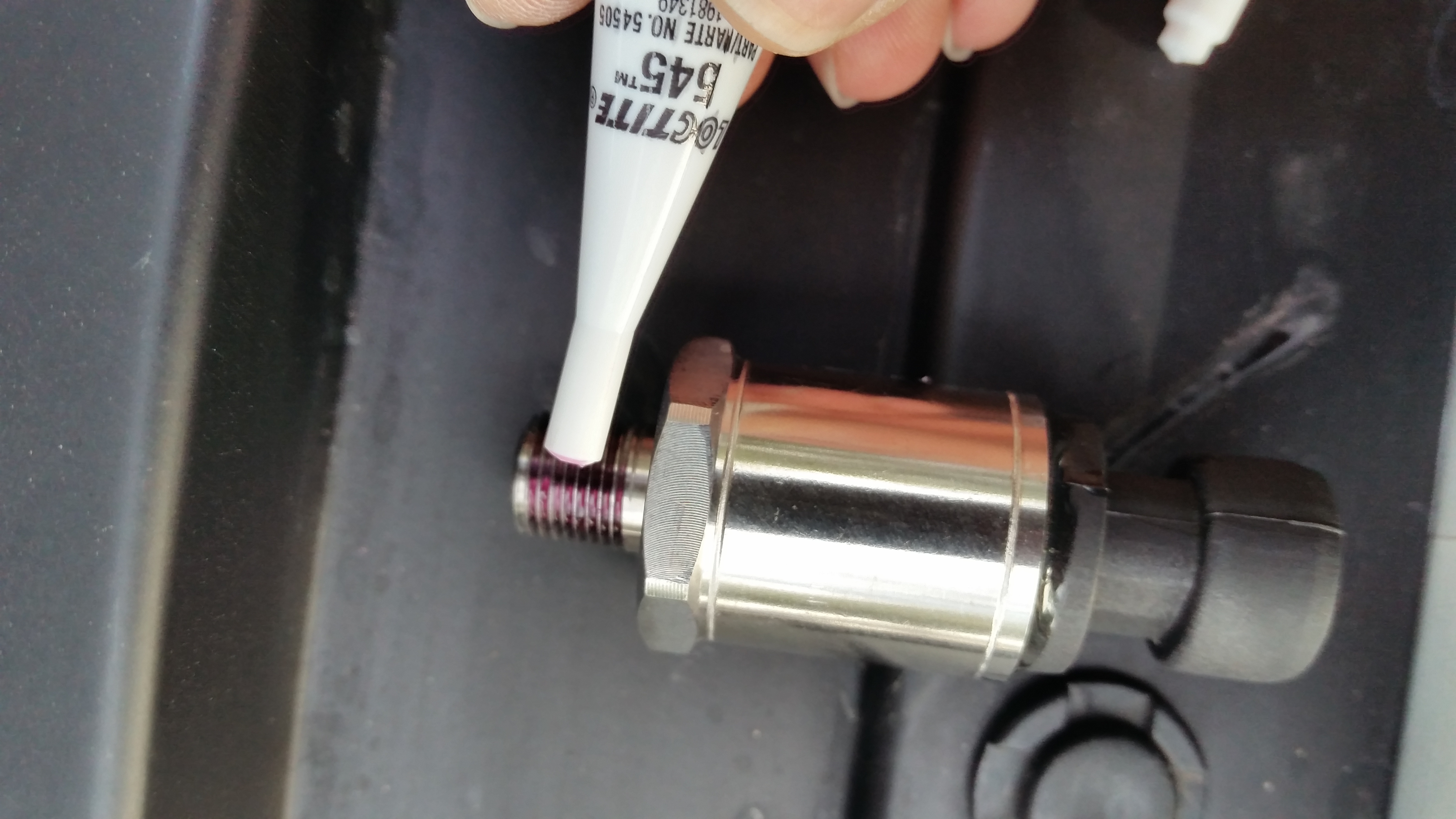
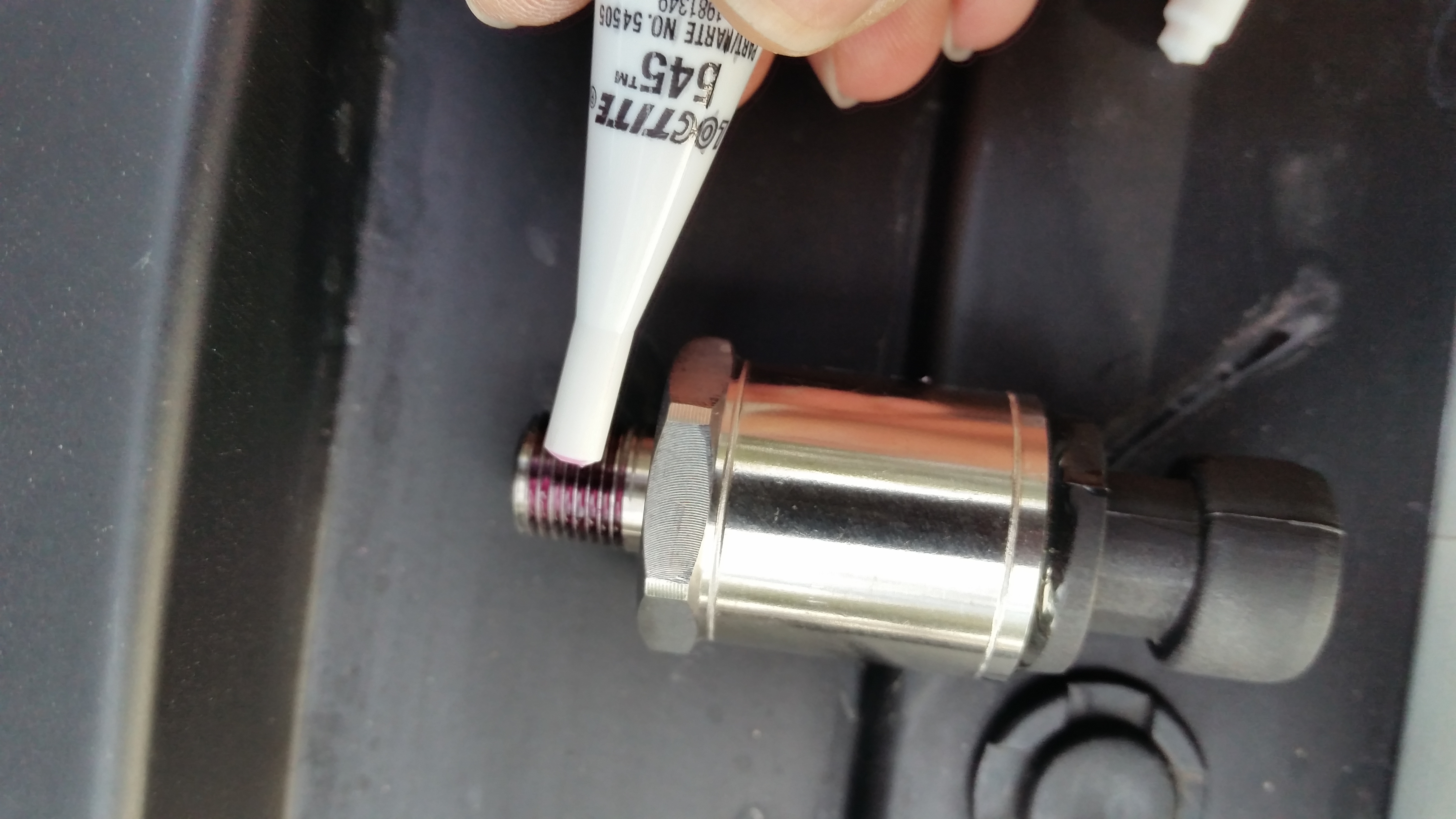
- Using the included thread sealant, coat the threads of the pressure sensor, making sure to ONLY coat the threads so the sealant cannot contaminate the fuel.
- Install the fuel pressure sensor into the adapter. The threads are tapered so the sensor does not need to be down all the way in order to be sealed so once it's tight you should still see quite a few threads still showing. As shown in the picture, it is quite close to the line and installing it too far can cause it to hit the line and either prevent the assembly from being installed or potentially damage the sensor/line.
Note: The picture is at a slight angle and is without the retainer and o-rings found in the fitting. While the sensor doesn't need much exposure since there will be close to zero flow needed at the sensor, there will be more sensor exposure than is shown. The picture is intended as a representation to show you how things fit together and the consequences of tightening it too much - Tighten the sensor using a 7/8" Deep Socket and socket wrench - do not hand tighten.
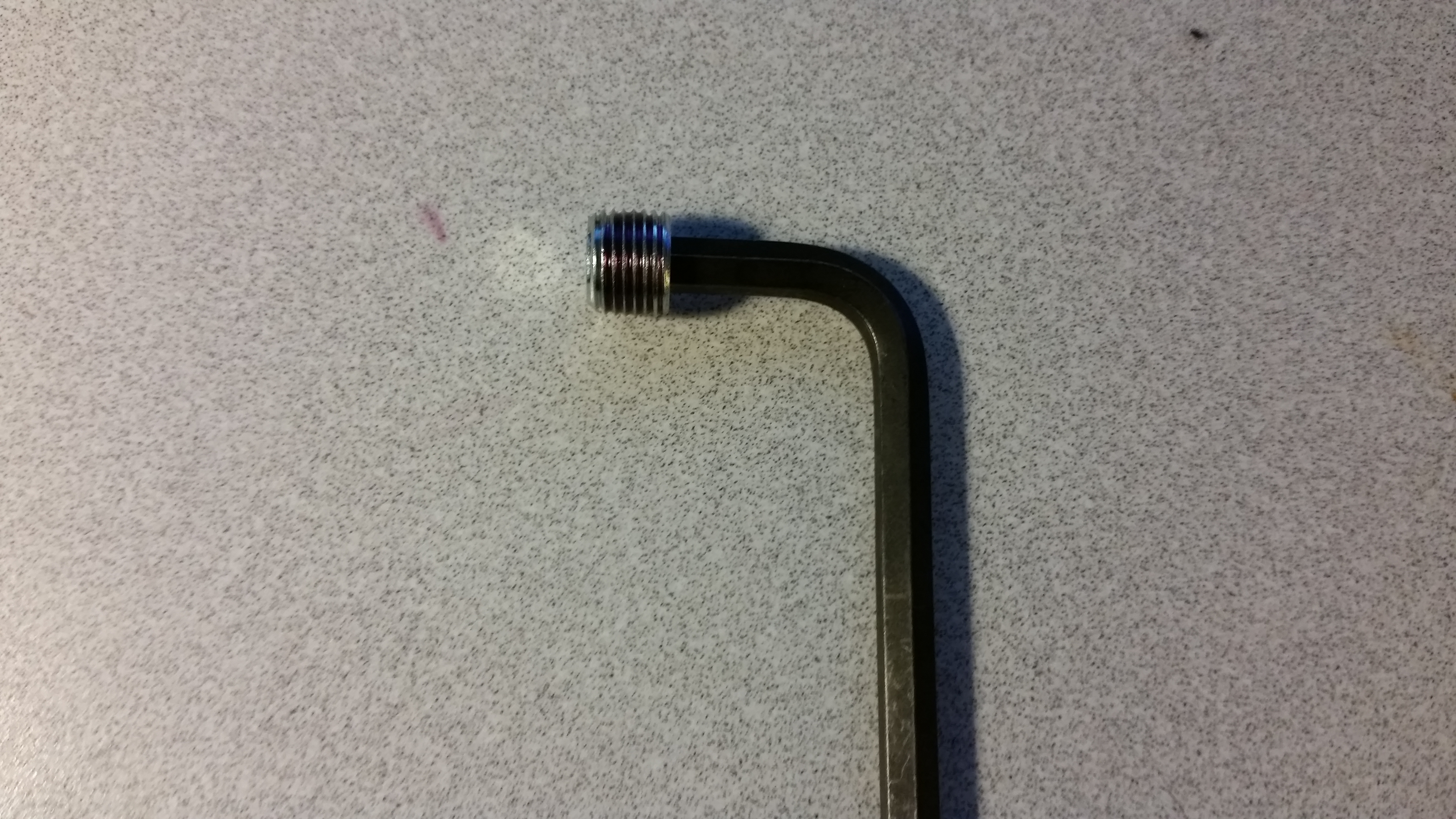
- Using a 3/16" hex key, coat the threads of the included plug and install on the side opposite of the pressure sensor.
- If for any reason you need a substitute sealant, YELLOW thread tape from a local hardware store can be used.
There are two locations where you can install the Fuel Pressure sensor. You can install it to A) directly to the feed line near the intake manifold, or B) onto the COBB Ethanol Content Sensor depending on our chart above.
Failure to install your fitting in the correct location can lead to damage to your vehicle or the adapter that will not be covered under warranty.
- To install the Fuel Pressure Sensor to the feed line at the intake manifold, lightly lubricate the o-ring inside of the adapter with silicone spray or a synthetic grease and place the assembled adapter onto the fuel line. Plug the adapter onto the male fuel fitting.
- 05-06 non quick-connect fuel line cars only!!! To install the Fuel Pressure Sensor to the COBB Ethanol Sensor directly, lightly lubricate the o-ring inside of the adapter with silicone spray or a synthetic grease and place the assembled adapter onto the fuel line. Plug the adapter onto the male fuel fitting.
- To install the Fuel Pressure Sensor to the feed line at the intake manifold, lightly lubricate the o-ring inside of the adapter with silicone spray or a synthetic grease and place the assembled adapter onto the fuel line. Plug the adapter onto the male fuel fitting.
- Reconnect the return fuel line hose to the return line from the intake manifold side and the firewall side.
- Reinstall the battery. Once the installation is complete, reconnect the negative battery terminal, then positive, and prime the fuel system by cycling the key between the "OFF" and "RUN" positions at 3-second intervals. 4 or 5 cycles will be adequate to re-pressurize the system. CAREFULLY INSPECT FOR LEAKS AND IMMEDIATELY CORRECT IF ANY ARE FOUND.
- Start the vehicle and again inspect for any leaking or abnormalities. Shut the engine off immediately if any fuel leaks or other issues are found.
Installation On COBB Fuel Rail and Lines
- Using the included thread sealant, coat the threads of the pressure sensor, making sure to ONLY coat the threads so the sealant cannot contaminate the fuel.
- Install the fitting using a 7/8 wrench into the provided AN fitting
Install the AN fitting onto either the feed or return line, it will work either way as they are both before the regulator.
Do not put any thread sealant onto the AN fitting ends, only on the pressure sensor where it installs to the fitting.
Harness Installation
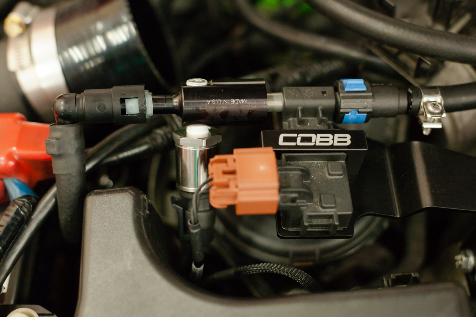
- Plug the 3 or 5-pin connector into the sensor, and route the harness alongside/under the intake manifold.
- Loosen the clamps to the air intake tube (the black silicon tube in this image) using a flat-head screwdriver, and remove the intake tube.
- The Passenger TGV is visible immediately beneath the tube.
- Disconnect the factory harness from the TGV, and install the COBB harness in-line to the TGV.
Calibration Data
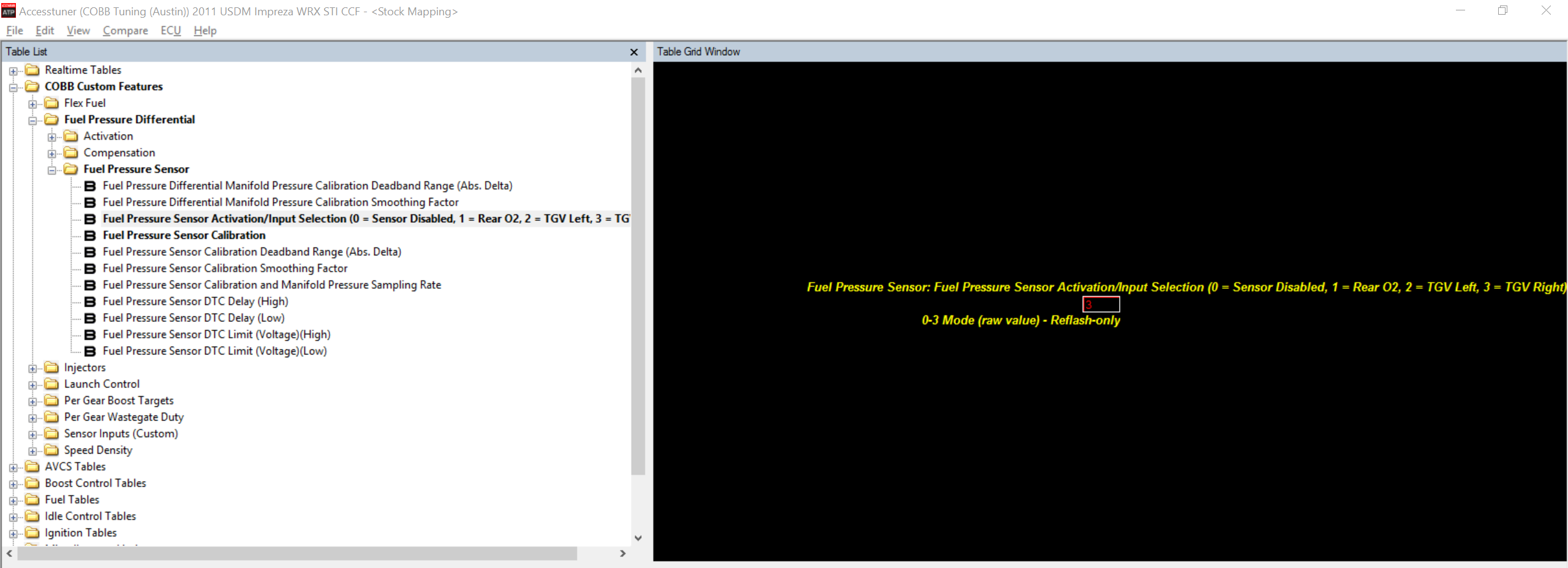
Fuel Pressure Sensor Input Selection = TGV Right (click to expand)
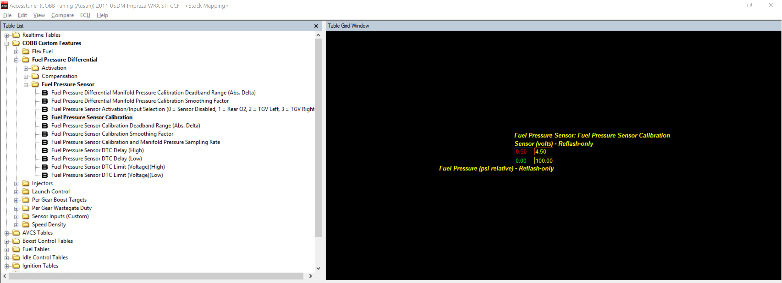
Sensor calibration: (click to expand)
0.5 V = 0 psi
4.5 V = 100 psi
Links
COBB Product Install Instructions for Subaru Vehicles
Main Installation Instruction Repository for Subaru Parts
COBB Customer Support Web Support and Tech Articles: COBB Tuning Customer Support Center Email: support@cobbtuning.com Phone support available 9am to 6pm Monday-Thursday. 9am to 4pm Friday (CST) 866.922.3059 return to www.cobbtuning.comContact Us:
Copyright 2024 © COBB Tuning Products LLC. All Rights Reserved. | www.cobbtuning.com

.jpg?version=1&modificationDate=1682906824120&cacheVersion=1&api=v2&width=535&height=401)
.jpg?version=1&modificationDate=1682906824289&cacheVersion=1&api=v2&width=534&height=400)
.jpg?version=1&modificationDate=1682906824415&cacheVersion=1&api=v2&width=301&height=401)
