Focus RS Tuning Guide
- Brandyn Mowat

![]()

USDM/CHDM/EDM Ford Focus RS
Introduction
Getting to know the Ford Focus RS
Here we will go over a few of the basic details and terminologies that are specific to Ford before we begin tuning on a COBB Accessport equipped Ford Ecoboost vehicle.
- 3D Breakpoint Setup– The Ford ECU uses a new style of 2D axes in select 3D tables. In these tables both the X and Y axis have "paired" data. On tables that would require it, we have broken these out for editing in separate folders. The axes are generally index based and may require manipulation to both the index and/or the data to properly display graphs or to utilize greater breakpoint resolution. Our v300 OTS maps should have good base settings which can be modified further if need be. More details on this can be found in section L.
- Boost Control – The RS does not directly target boost in stock form but rather a target engine torque. Engine torque is calculated based on numerous variables such as: pedal position, air flow mass, knock, OAR, and RPM. The general strategy of the RS is to convert and crosscheck mainly torque, load, and airflow, choosing the lowest value, and then clipping the engine output at that value. Raising WGDC directly with out modifying other limiters will have little to no impact other than to cause undesirable PID activity and oscillations.
- Fuel Control – The RS operates in a constant closed-loop state, constantly utilizing the A/F values in its tables and making closed loop adjustments via the feedback from the factory wide-band O2 sensor.
- Ignition Control – The Ford RS consists of four primary methods to control spark: MBT, Borderline, Cylinder Pressure, and Pre-Ignition. The ECU also allows full dynamic advance and retard based on octane learning and knock sensor feedback. There are up to 16 primary tables for each method, along with accompanying compensations. The majority of heavy load operation will take place in the borderline timing tables, however this can be clipped by any other timing table from the other categories if they are lower. Watching the Spark Source and HDFX monitors will give you a good idea of which set of tables are being utilized at any given time.
- MAP Based – These vehicles use a MAP based airflow system. This is also known as Speed Density.
- Throttle Closures – The primary method of controlling torque on the RS is done with the assistance of the drive-by-wire throttle system. The factory tune allows the throttle to close to less than 20* (of the 82* max) which can result in extremely consistent torque delivery. There are two main offenders that will result in throttle closures: Load and Boost. We recommend adjusting these limits higher to take full control of the throttle. The most common throttle closures will happen at peak torque when TIP Actual is likely surpassing TIP Desired. Adjusting the WG Canister Pressure Desired (FF) (OEM) table is the best way to help reduce throttle closures. All throttle closures are not necessarily bad. If you are hitting your load and torque targets and the transitions are smooth throttle closure can be an ideal means of hitting peak torque quickly while also maintaining a safe torque value.
Throttle Closure Safety Limits – The OEM calibration has precautions in place to close the throttle if ECT or EOT achieve certain temperatures. The v300 and higher maps have these limits lowered to a more conservative level to bring thermal management issues into perspective before they become critical. v300 maps will start to limit throttle when ECT is greater than 230*F/110*C and/or EOT is greater than 270*F/132*C. A DTC will also trip when these limits are triggered to assist in diagnostics.
Focus RS- Octane Adjust Ratio (OAR) - A learned multiplier for ignition timing where optimal numbers are -1 and 1 will indicate less than optimal settings or fueling. The value will also impact other strategies like Low Speed Preignition (LSPI)
- Over-temp Conditions – There are numerous watchdogs in the ECU that can put the car into an over-temp mode. During this mode, additional fuel is injected in an attempt to cool the car down and bring conditions back to normal. This will result in poor performance and use excessive fuel. Care should be taken to adjust these temperatures with the appropriate sensors in place to ensure optimal power delivery and engine safety are achieved.
Raptor- Knock Octane Modifier (KOM) - A learned multiplier for ignition timing where optimal numbers are +1, and -1 will indicate less than optimal settings or fueling. The value will also impact other strategies like Low Speed Preignition (LSPI). Those familiar with other EcoBoost Fords will see strong similarites between KOM and OAR - KOM simply acts as an inverted OAR.
- Octane Adjust Ratio (OAR) - A learned multiplier for ignition timing where optimal numbers are -1 and 1 will indicate less than optimal settings or fueling. The value will also impact other strategies like Low Speed Preignition (LSPI)
Commonly Used Acronyms
|
|
Preparing to calibrate the vehicle
Before anything make sure you go over our Pre-Tuning Guide
For information on using our software check out these areas for specific articles
- Accesstuner Tutorials: How to set default log save file
- Accesstuner: Map Comparison
- Pre-Tuning Guide
- Saving a map in Accesstuner Pro so anyone can view (Leave a map unlocked)
- How to Calculate Offset and Gradient for Pressure/MAP Sensors
- Accesstuner Bulk Map Operations
- Custom Feature Cruise Control Button Assignments
- Accesstuner Software Bulletins for Ford
- Ford Focus RS - 2016 GRCK2 Accesstuner Definition Upgrade to 2017 GRCK4 Strategy
- Tech Bulletin - Focus/Fiesta ST CCF Gen2 - VE Compensation (VCT) Tables
- Tech Bulletin - Ford Accesstuner - TIP Boost Error Scaling Issue
- Tech Bulletin - Ford Accesstuner - WGDC Compensation Modes
- Tech Bulletin - Octane Adjust Ratio
- Tech Bulletin - Configuring a Base Map for a Big-Turbo Ford EcoBoost
- Engine & Transmission Monitor List for Ford Vehicles
- Knowledge Base Articles for Ford
- Ford Tuning Guide
- Ford Truck Tuning Guide
- EcoBoost Wastegate Strategy Addendum
- COBB Custom ECU Features
- Ford EcoBoost Speed Density Guide
- Ecoboost Mustange TCC Lockup Control
- Ford Traction Control
- F150 - Raptor TCM Tuning Guide
- Focus RS Tuning Guide
- Gen2 Raptor/Ford F150 10-Speed Transmission Tables
- Cobb Custom Features: Ford TransBrake Tuning Guide
Vehicle Specific Questions
Step 1 – What is the mechanical configuration of the vehicle?
The first step in tuning these vehicles is choosing a COBB Tuning Off-The-Shelf (OTS) calibration that most closely matches the mechanical components and modifications of the vehicle to be tuned. Refer to our map notes and apply the map that most closely matches your vehicle's mechanical configuration.
Step 2 – What fuel is the vehicle using?
Please note that COBB Tuning offers select performance calibrations for three different fuels: 93 octane (98 RON), 91 octane (95 RON). ACN91 octane from Arizona, California, or Nevada is compatible with our 91 octane calibrations. All calibrations are made with fuel that contains 10% ethanol. If you are using 94 octane with 0% ethanol we recommend running the 91 octane calibration. If your fuel does not meet the standard of the available COBB maps you will need to adjust the calibration accordingly. Take a moment to compare and contrast timing, boost, and ignition tables from each type of calibration. Higher octane fuels support more ignition timing, higher boost levels, and leaner air to fuel mixtures compared to lower octane. Using a map designed for high-octane with low-octane fuels may result in engine damage.
Step 3 – What type of air intake is on the vehicle?
These vehicles utilize manifold absolute pressure (MAP) sensors located pre and post throttle body to measure the mass of air entering the engine. Filter configuration does not necessarily require tuning but heavily contaminated air filters of both OEM and aftermarket construction were found to reduce power output at moderate to high engine speeds. Frequent air filter cleaning and/or replacement is recommended for best performance and engine protection.
Getting Started
Whether you're starting from a stock calibration or a Cobb OTS map, you will want to get a baseline of current engine operation in order to decide your next steps, tuning-wise. The following list will provide you with information on which tables are active under various pedal position and load conditions.
Good Parameters To Log - Focus RS
- Accel. Pedal Pos. – Accelerator pedal position (this is direct pedal input before translations).
- Actual AFR – Wideband front oxygen sensor reading converted from Lambda to AFR..
- Airflow Mass – The calculated airflow through the engine and is used for almost all flow based tables.
- Boost Pressure – Manifold pressure (relative). This is MAP minus Barometric pressure.
- Charge Air Temp. – (CAT) Charge air temperature as measured post throttle body. It is combined with the MAP sensor on the intake manifold.
- Coolant Temperature – Engine coolant temperature.
- Engine Speed – Engine speed in revolutions per minute (RPM).
- ETC Angle Actual – Electronic throttle control actual angle.
- Fuel Rail Pressure Actual – The fuel pressure as measured in the fuel rail.
- Ignition Timing Corr. Cyl (1-4) – Individual cylinder timing correction in degrees (+/-).
- Ignition Timing Cyl (1-4) – This is the final actual ignition timing after all correction and adjustments in degrees before TDC.
- Load Actual – This is actual calculated engine load value (absolute).
- WGDC Actual – This is the final wastegate solenoid duty cycle after PID system compensations.
- STFT – Short term fuel trims displayed in percent.
- LTFT – Long term fuel trims displayed in percent.
Good Parameters To Log - Raptor
- Accel. Pedal Pos. (Translated) – Accelerator pedal position after drive mode & Dynamic Pedal Control translations
- Actual AFR (Average) – Wideband front oxygen sensor readings converted from Lambda to AFR, averaged between Bank1 and Bank2.
- Airflow Limit Source – The currently active load/airflow limiting source; reference the monitor guide to understand the translations this monitor and the tables currently in use.
- Boost Pressure – Manifold pressure (relative). This is MAP minus Barometric pressure.
- Charge Air Temp. – (CAT) Charge air temperature as measured post throttle body. It is combined with the MAP sensor on the intake manifold.
- Coolant Temperature – Engine coolant temperature.
- DFI/PFI Split Actual - The proportional split of fuel delivery between the direct fuel injection (DFI) system and the port fuel injection (PFI) system; 0% = all DFI, 100% = all PFI.
- Engine Speed – Engine speed in revolutions per minute (RPM).
- ETC Angle Actual – Electronic throttle control actual angle.
- Fuel Rail Pressure Actual – The fuel pressure as measured in the fuel rail (high pressure system).
- Fuel Source - The currently active fueling mode; reference the monitor guide to understand the translations between this monitor and the tables currently in use.
- HDFX Weight Table 01-15 - The proportional weights of all different HDFX modes; HDFX modes will be referenced by speed density tables, ignition timing tables, and load limiting tables.
- Ignition Timing Corr. Cyl (1-6) – Individual cylinder timing correction in degrees (+/-).
- Ignition Timing Cyl (1-6) – This is the final actual ignition timing after all correction and adjustments in degrees before TDC.
- Knock Octane Modifier - This is the global octane learning system that is used on the Raptor; very similar to OAR, but inverse. +1 indicates maximum timing advance and maximum load limits, -1 indicates minimum timing advance and minimum load limits.
- Load Actual – This is actual calculated engine load value (absolute).
- Load Desired (TQ Control) - This is the current load limit.
- LTFT – Long term fuel trims displayed in percent.
- Power Demand Status - Indicates whether or not the power demand threshold conditions have been met; relates to fueling and load limiting. 0 = not active, 1 = active.
- STFT – Short term fuel trims displayed in percent.
- Spark Source - The currently active spark mode; reference the monitor guide to understand the translations between this monitor and the tables currently in use.
- TIP Actual Absolute - Actual throttle inlet pressure (pre-throttle body), in absolute pressure.
- TIP Desired Absolute - Target throttle inlet pressure (pre-throttle body), in absolute pressure.
- Turbo PID I-Term - The integral component of the PID boost error system. This is added to the feed-forward wastegate position base table values.
- Wastegate Position – This is the final commanded wastegate position for the wastegate actuators after PID system compensations.
Calibration Refinement (Using a Load-Based Chassis Dynamometer) Using OEM Strategies
A: Perform Initial Testing at Low Load / Low Boost
After choosing the most appropriate starting point calibration, prepare to test and refine the calibration on a load-based chassis dynamometer. When creating a custom tune, it is best to begin testing under low load and boost conditions. This can be done many ways but the quickest is by lowering values from the "TIP Desired Max. (Ceiling) Non 5-Way" table since this table can be tuned in realtime. This will lower the maximum allowed throttle inlet pressure. Testing done at lower boost will allow you to assess the calibration without putting the motor under potentially dangerous conditions. Start the tuning process by loading this "low boost" starting point calibration onto the vehicle.
B: Simplified Overview of Torque/Load/Airflow/Boost Control Strategy
Here you will find a very generalized overview of how the control system works, more details are in the following sections.
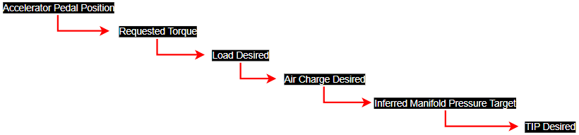
Each of these steps has a series of clips, compares, translations, etc... that all must be taken into account when trying to raise power output. The ECU will always take the lowest value when comparing targets/requests within a subsystem before pushing it onto the next calculation. For instance, If your Torque Maximum (CVC) is 350 and your Requested Torque is 375 it will compare the two, pick the lower one(350) and then send that out as TTL (Final) to be converted into load and output as Load Desired (TTL). Load Desired (TTL) is then compared with Load Limit (LSPI) and Load Max Achievable and the lowest of those values is sent out as Load Desired (Tq Control). Load Desired (TQ Control) is then fed into a complex SD calculation to find an Inferred Manifold Target Pressure, so on and so forth. This is all detailed in Flow Charts below.
C: Raising Torque & Load
The Focus RS ECU is primarily torque, load, and airflow based. It uses a complex lookup routine to crosscheck several variables based on conditions to achieve its target torque. Boost levels will be dynamic based on environmental conditions such as barometric pressure, ambient temperature, charge air temperature, etc...
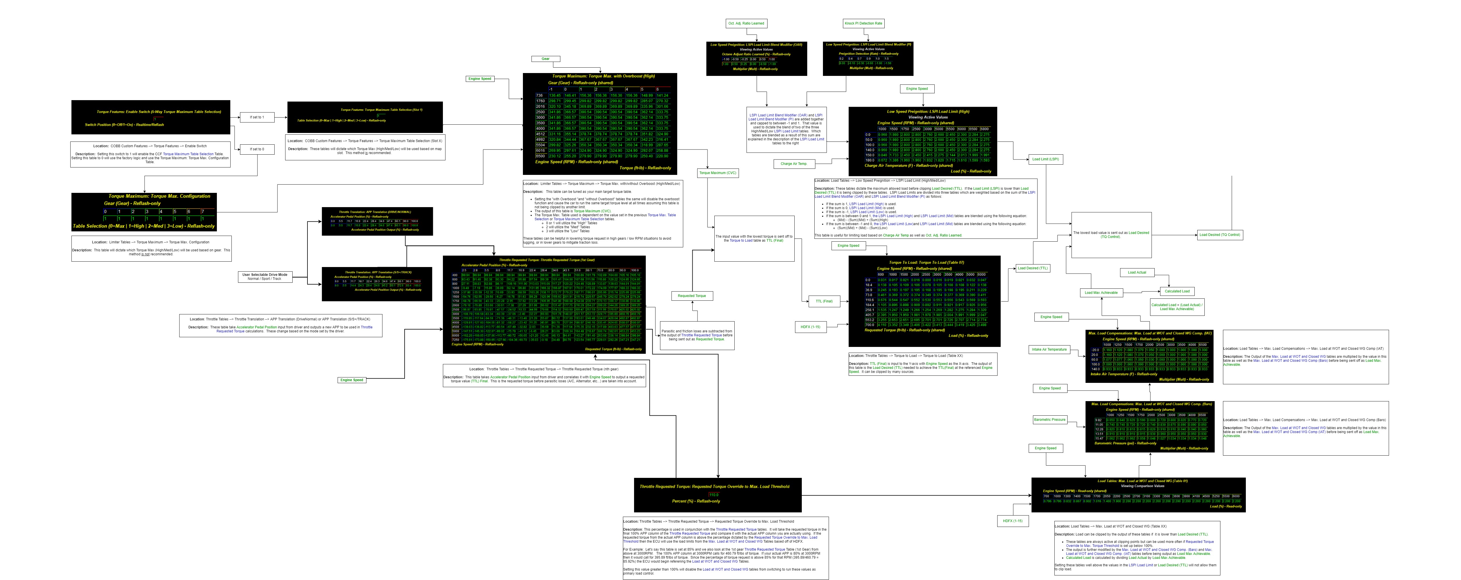
The RS relies heavily on clipping values based on the lowest input. For example when trying to decide what the TTL (Final) will be the ECU will cross check the outputs of different torque tables and choose the lowest value to pass off to be converted into load, that load value will be cross checked with other load values such as LSPI Load Limits or Max Load at WOT and again the lowest will be chosen to be sent off as Load desired which gets converted ultimately into a TIP desired. It is very convoluted but when all the tables are calibrated correctly the torque delivery is very consistent. It is highly recommended to learn the OEM logic. See the flow chart below for a more in depth overview of how the requested torque and load systems feed into one another from APP Input to Load Desired output.
Torque Request → Load Desired - Flow Chart
D: Boost Control
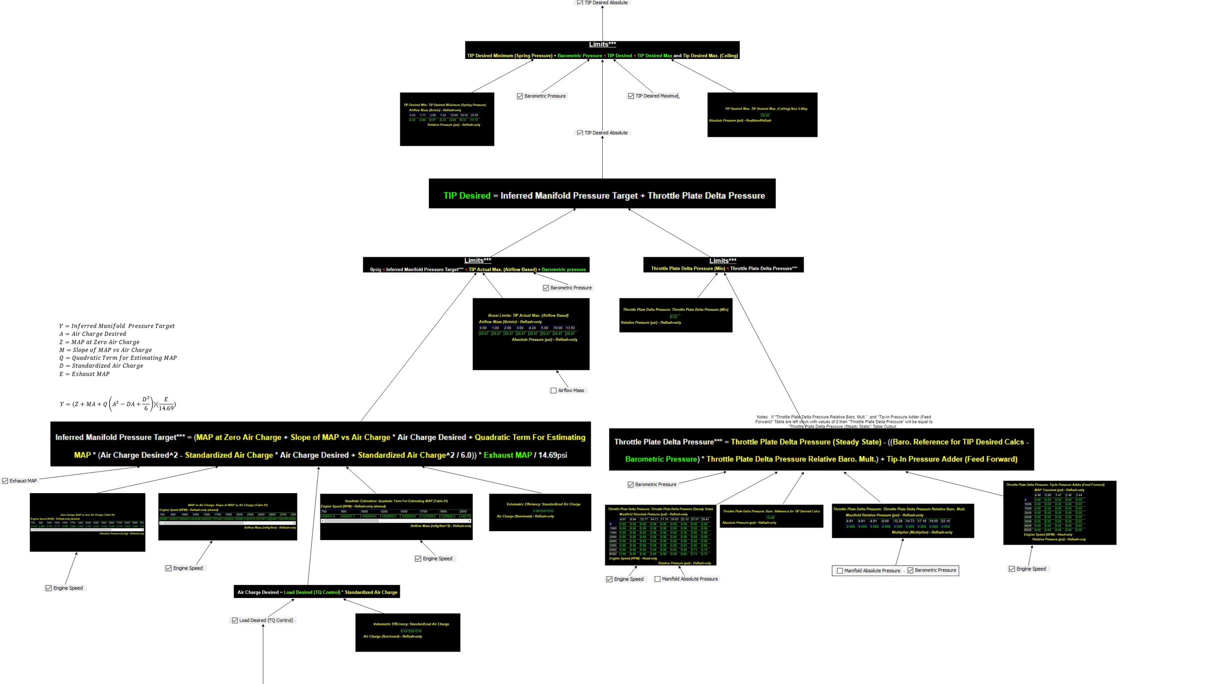
Boost targeting is as equally complex as the torque and load strategies used above. It generally takes the Load Desired TQ Control output calculated from the torque and load targets and runs that through an equation to come up with an Inferred Manifold Pressure Target.
The Inferred Manifold Pressure Target uses six variables in the calculation (shown below) and ultimately becomes your TIP Desired Absolute after a few limit and crosschecks.
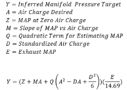
Use the flow chart below to help illustrate this process in further detail:
Load Desired → Tip Desired - Flow Chart
Notes on Boost Control
- Inferred Manifold Pressure Target is heavily based off of your VE tables. It is best to get your fuel trims dialed in before tackling boost control. Changes in your VE in order to compensate for fuel trims at the end of a calibration may require touching up boost control. We have also included in all v300 and higher OTS maps a base CCF VE table with VCT compensations that have been based off of a Focus RS in a stock parts configuration. Adjusting fuel trims via these tables will not impact your OEM SD tables, thus not impacting boost control.
E: Throttle Closures (TIP Desired vs. TIP Actual)
Ford Focus RS uses Electronic Throttle Control (ETC) aggressively to regulate torque. When tuned properly this system can be used to make torque delivery extremely consistent. And eliminate large torque overshoot(overboost) which overtime will bend rods and cause catastrophic engine failure. Generally, throttle closures happen when TIP Actual Absolute surpasses TIP Desired Absolute. Tip Actual Absolute calculation is detailed above via the intricate system of load and torque calculations. Generally raising Requested Torque will raise load, which will raise boost, however you may come into certain situations, particularly with parts our OTS maps were not designed for, where TIP Actual far surpasses TIP Desired, or vice versa, and large throttle closures occur over a broad RPM range. The factory calibrations relies very heavily on throttle closures to regulate torque. Our v300 and up OTS maps alleviate a large majority of the closures but still rely on it for initial torque control as boost hits.
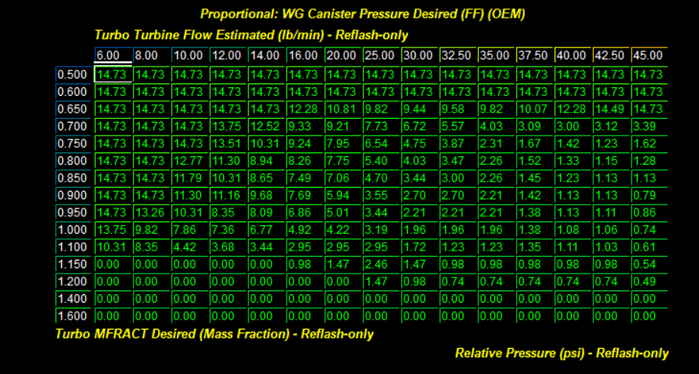
WG Canister Pressure Desired (FF) (OEM) will be your main table to adjust when it comes to closing the gap between TIP Actual and TIP Desired. It is the main variable in the x-axis of the WGDC Base table. More info for these two tables is found to the right →.
Here is a basic rule to follow when adjusting canister pressure to help offset a TIP Error in TIP Actual & Tip Desired differential:
- TIP Actual < TIP Desired (Positive Turbo TIP Error (Desired-Actual))
- Decrease WG Canister Pressure Desired (FF) (OEM)
- TIP Actual > TIP Desired (Negative Turbo TIP Error (Desired-Actual)
- Increase WG Canister Pressure Desired (FF) (OEM)
- Notes
- Disabling the PID Control while trying to dial in Canister Pressure and overall WGDC will help keep things consistent.
- This can be done by taking the following steps:
- Set PID P-Term Gain Multiplier table to 0
- Set PID D-Term Gain Multiplier table to 0
- Set the PID I-Term Max. & PID I-Term Min. tables to 0
- Don't forget to revert these settings when you are satisfied.
- This can be done by taking the following steps:
- The PID KAM Learned Values table can be referenced after the car has been driven for some time and those values can then be ported into your main WG Canister Pressure Desired (FF) (OEM) Table to even further refine boost control overtime.
- Rescaling the X-Axis of the WG Canister Pressure Desired (FF) (OEM) can further enhance control of boost, particularly during spool and initial boost onset. See our v300 or higher OTS maps for a good example.
- Turbo Turbine Flow Estimated is based off of the sum of Air Flow Mass and Fuel Flow Mass changes in lambda can have an impact on the x-axis of the WG Canister Pressure Desired (FF) (OEM) Table. See our v300 or higher OTS maps for a decent place to start for target lambda.
- Disabling the PID Control while trying to dial in Canister Pressure and overall WGDC will help keep things consistent.
To reiterate, some throttle closures are not necessarily bad and play a vital roll in torque management. As long as the closures are not interfering with smooth torque delivery at your target torque they should not need to be changed.
- WG Canister Pressure Desired (FF) (OEM)
- X-Axis - Turbo Turbine Flow Estimated (lb/min)
- This axis is an estimate of the sum of Air Mass and Fuel Mass
- Monitor Name: Turbo Turbine Flow Estimated
- Y-Axis - Turbo MFRACT Desired (Mass Fraction)
- This axis is a desired ratio of exhaust mass flow through the turbine. An MFRACT of .75 would be desiring 75% of exhaust mass flow to pass through the turbine and 25% to bypass the turbine via the wastegate.
- Monitor Name: Turbo MFRACT Desired
- Table Output Monitor Name: Turbo PID WG CP FF Base
- Location: Boost Control Tables → Wastegate → Wastegate Dynamics → Proportional
- X-Axis - Turbo Turbine Flow Estimated (lb/min)
- WGDC Base
- X-Axis - Turbo PID WGDC Base X
- This axis is calculated using the following formula: (Turbo PID WG CP FF Base + Barometric Pressure - Compressor Inlet Pressure + Turbo PID I-Term + Turbo PID P-Term + Turbo PID D-Term) ).
- Monitor Name: Turbo PID WGDC Base X
- Y-Axis - Turbo PID WGDC Base Y
- This axis is calculated using the following formula: (Compressor Outlet Abs. Pressure - Compressor Inlet Abs. Pressure)
- Monitor Name: Turbo PID WGDC Base X
- Table Output Monitor Name: Turbo PID WGDC Base
- Location: Boost Control Tables → Wastegate → Wastegate Base Tables
- X-Axis - Turbo PID WGDC Base X

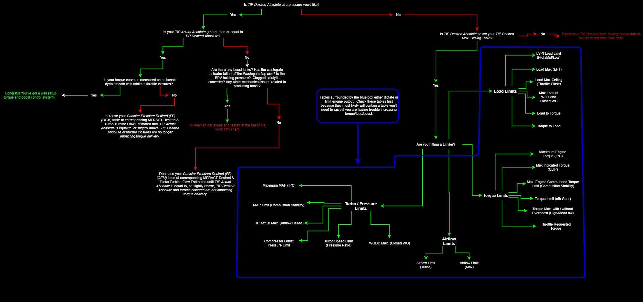
F: General Overview of Boost Control Work Flow
Here is a generalized breakdown of how to approach raising TIP Desired Absolute by manipulating limits, targets, and requests from various torque/load/airflow based systems.
TIP Desired Absolute Work Flow
G: Tuning for appropriate Air to Fuel ratios (Lambda)
The ideal air to fuel ratio depends upon fuel quality. Higher octane fuels are more detonation resistant and therefore can be run at leaner air to fuel ratios. Leaner Air to Fuel ratios produce higher power but also create more heat. Excessive heat can lead to detonation. Lower octane fuels such as 91 octane (95 RON) are more prone to detonation and therefore generally require a richer air to fuel ratio. Rich air to fuel ratio combustion produces less heat and therefore less detonation.
These vehicles utilize an internal wide-band oxygen sensor to monitor fuel mixtures. The sensor is located in the down pipe. The target values for the Air to Fuel mixture can be monitored using the following, Commanded EQ Ratio and Desired AFR (Power Demand). The currently measured air to fuel mixture can be seen using the Actual AFR or Actual AFR (SP) monitors. The adaptive adjustments made by the ECU are monitored using Short Term Fuel Trim and Long Term Fuel Trim. The adaptive adjustments run full time in a closed-loop PID system.
The primary means to adjust fueling during WOT conditions is with the Desired Fuel Target (Power Demand) table. This table is referenced by ECT and Engine Speed. The targets in this table are used by the ECU to set the desired AFR (Lambda). The threshold for utilizing this table is determined by Accelerator Pedal Position input and is named Power Demand Threshold (APP). Under this threshold the car will run in Closed-Loop and attempt to achieve the Fuel Scalar Stoich. Setpoint.
H: Tuning for appropriate Spark Advance
The Ford Ignition Timing Strategy
The timing strategy in this ECU is extremely complex and robust. We highly recommend using one of our OTS maps as a base when beginning to tune. Below you will find a general overview of the ignition timing strategy and how it can be manipulated to ease tuning. Most of these tables are referenced by Engine Speed and Load Actual. Logging these parameters will allow you to reference the specific regions of these tables that may need to be edited to produce optimized ignition timing.
The ignition timing strategy decision logic
(Monitor Name) Spark Limit Source (+Corresponding Compensations) | (Monitor Name) Ignition Timing Base +Avg. of Timing Corr. Cyl 1-4 | (Monitor Name) Ignition Timing Requested This is the final requested timing target. |
1 = MBT Timing (MBT)
2 = Borderline Timing (BL)
4 = Pre-Ignition Timing (PRE)
5 = Cylinder Pressure Timing (CYL)
The ignition timing strategy post-decision "sandwich" logic
(Monitor Name) Ignition Timing Base Lowest of MBT, PRE, or CYL. | → | (Monitor Name) Ignition Timing Cyl 1-4 +/- Ignition Timing Corr. Cyl 1-4 | ← | (Monitor Name) Ignition Timing Ceiling Lowest of MBT, BL, PRE, CYL. |
Knock Sensor Dynamic Feedback
Ignition timing is also adjusted in response to detonation. The ECU can actively increase and reduce timing in response to detonation (or lack thereof). The ECU has the capability to make individual cylinder timing adjustments. This means that monitoring a single cylinder for timing correction will not result in a global picture of engine operations. Timing adjustments are logged with the "Ignition Timing Corr. Cyl 1-4" monitor. The amount of timing subtracted during knocking conditions can be adjusted with the "Knock Sensor Timing Decrement (Retard)" table. During non-knocking conditions, the ECU will attempt adjust timing in small increments up to the maximum value in the table "Knock Sensor Timing Max. (Advance)" or the delta of the Ignition Timing Ceiling and Ignition Timing Base tables; whichever is lower.
Ignition Timing Compensations
Ignition timing compensations exist for each timing method except for the Pre-Ignition Timing Limit (Ceiling). Be mindful of the total value of each group of compensations when developing a desired timing curve. Since the ECU chooses the lowest of these tables, various compensations could push one table higher than others and drastically change the base or ceiling chosen.
Ignition Timing General Guidelines
Generally speaking, higher ignition timing supports higher torque and greater power. However, ignition timing should be increased with great caution. Higher timing yields higher cylinder pressures and this is limited by fuel quality and mechanical limitations of the engine. Too much timing will produce negative knock corrections when fuel quality is limiting. When fuel quality is high, ignition timing should ONLY be added when its addition produces a substantive increase in torque and power. If increased timing does not increase torque the extra cylinder pressure is simply producing unnecessary stress on engine components.
I: Tuning Ti-VCT (Variable Camshaft Timing)
The VCT operation of this car is well optimized from the factory for the stock turbo. These tables may need to be altered considerably for larger turbocharger, or aftermarket engine components. Also note that changing VCT may require changes to the Speed Density Tables to ensure accurate calculations. Altering VCT can also change how boost is controlled since the HDFX is changed based on the cam pairing . The SD tables used are based on HDFX and are used while calculating an Inferred Manifold Pressure Target.
J: Integrating all tuning parameters for the ideal Calibration
The ideal calibration for your vehicle is a combination of all major tuning areas outlined above. Like any performance vehicle, the EcoBoost engines will make the most power when run lean with the maximum amount of ignition timing that the ECU will allow without detonating. However, this ideal of 12.5:1 air to fuel ratio and high ignition timing is not realistic for most configurations and fuels in forced induction vehicles. The only way to determine if a calibration is ideal is to run the car on a load-based chassis dynamometer where the impact of calibration changes is easily measured. For example, addition of ignition timing that does not result in increased torque is a not ideal. If additional timing does not create power then you are simply adding stress to the engine components without tangible benefit. The same is true of boost and air to fuel ratio. If you can run the vehicle at a richer air to fuel ratio without losing power this is more ideal than running the car lean. If increasing boost does not yield considerable power gains the turbo may simply be out of its efficiency range. In this scenario less boost may produce more power. To get a coarse idea of how the ideal tune looks on your fuel type and mechanical configuration, examine the COBB OTS maps and map notes.
K: Precautions
Boost
The stock turbocharger can produce boost levels in excess of 26psi. This boost level can generate enough cylinder pressure to cause engine damage. Be cautious when adjusting boost control parameters. Be particularly cautious when any mechanical component of the boost control system is altered.
Fuel Pressure
The stock high pressure fuel system is pushed close to the limit on the OTS calibrations. Watching HPFP Commanded, Fuel Rail Pressure Actual, Fuel Rail Pressure Desired, and Fuel Pressure Error will give you a good idea of how the High Pressure system is operating. Since the HPFP is bound to the cam and can only pressurize fuel based on engine rotations the highest demand on the HPFP is at peak engine torque when engine VE is the highest. When HPFP Commanded is at 100% the HPFP is running at full capacity. We have introduced a logic fix for the PID control of the HPFP in the v300 OTS maps and v2.0.0.0-16211 ATP/ATR to help fix some OEM pressure issues.
Sensor Limits
Engine control is entirely dependent upon accurate readings from the vehicle sensors. Stock vehicles are capable of producing sufficient airflow to push some of these sensors to their limits. Beyond the limits of the stock MAP sensor (4.985 volts – 32psi) the ECU has no way to properly control the motor. Many sensor calibrations are available in the software should you choose to change from factory pieces.
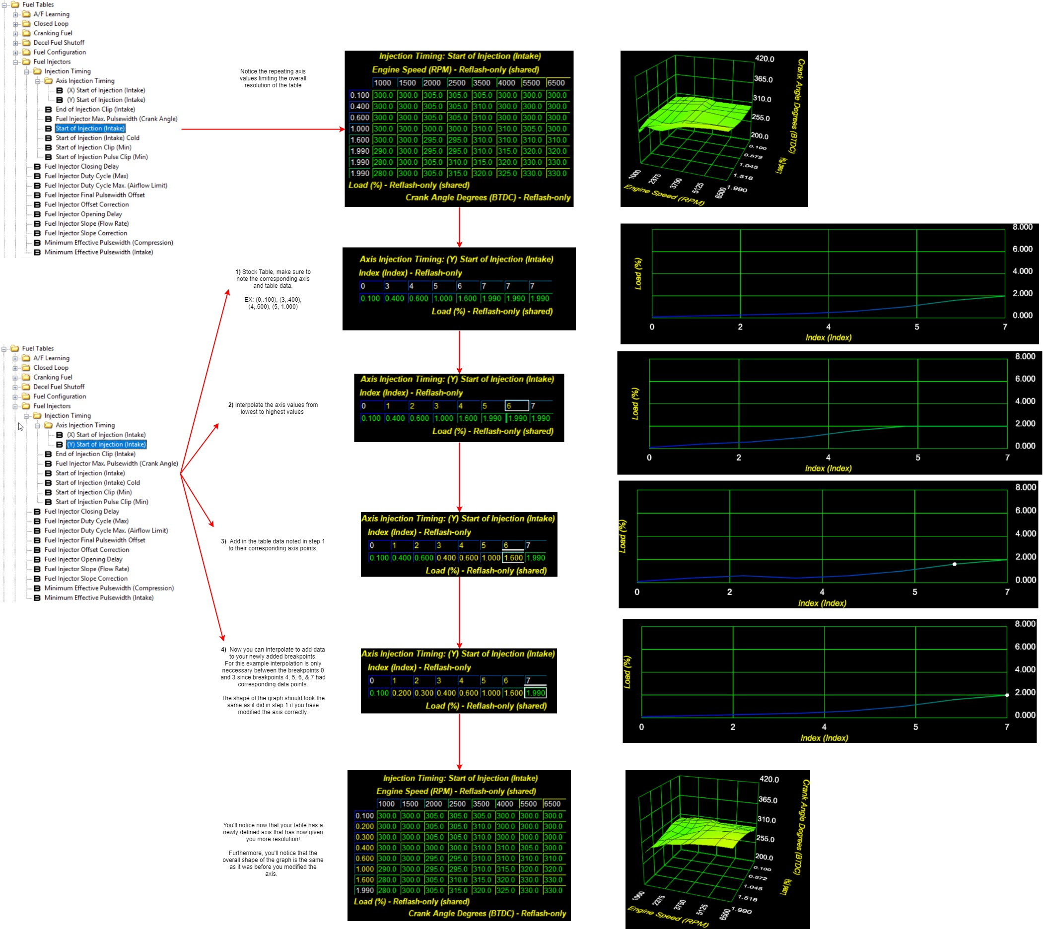
L: Definable Axis Breakpoint Setup
You have probably noticed in AccessTuner there are a series of tables called Axis Fuel Pressure , Axis Closed Loop, etc... These tables define the axis lookup values that are used in conjunction with the table and are used to reference output data. They look peculiar in stock form and will require a bit of finesse to set up properly. They can wreak havoc if modified incorrectly, simply interpolating the table doesn't work. Our v300 and higher maps will have these values setup for you already and should work well on stock to FBO vehicles.
Here is a short work flow chart on how to properly modify these tables:
Fuel Injection System
The EcoBoost platform utilizes direct injection versus conventional port injection in its turbocharged engines. In direct injection the gasoline is highly pressurized, and injected via a common rail fuel line directly into the combustion chamber of each cylinder, as opposed to conventional multi-point fuel injection that happens in the intake plenum, or cylinder port. This gives the engine many advantages for improved fuel efficiency under light load conditions, and also allowing a leaner Air/Fuel ratio.
The major advantages of the EcoBoost directed engines are increased fuel efficiency and higher power output. Gains are achieved by the precise control over the amount of fuel and injection timings that are varied according to the load conditions. Ford utilizes the throttle plate primarily for boost and torque control; engine speed is controlled by the ECU, which regulates fuel injection function and ignition timing.
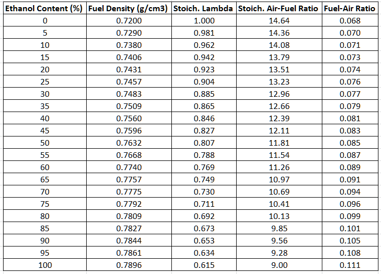
Fuel Settings Matrix for ethanol content (reference only)
Introduction to HDFX
We often receive questions about the engine control strategies being utilized in the Ford Ecoboost ECU. While most of the answers to these questions fall under information we have available in our Tuning Guide, there are some more advanced topics that have recently become necessary to explain and explore. In this document we will introduce you to a more technical understanding on how these engine controls operate using Ford's HDFX strategy and the way Volumetric Efficiency is determined.
What is HDFX?
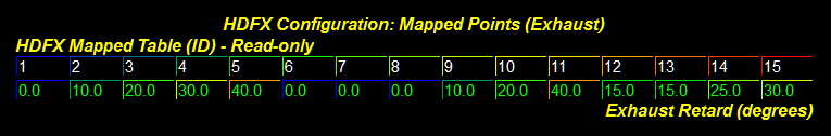
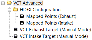
HDFX stands for "High Degree of Freedom Executive." It is a strategy that Ford has implemented to allow dynamic blending between a series of calibrated tables. You've likely seen these table sets (Table 01 – Table 15) in our software and wondered about their relationship to one another.
These tables are individually calibrated from Ford for the respective VCT (Variable Cam Timing) angle pair as defined by the pairing reference shown above. From left to right, these mapped pairs represent Table 01 – Table 15. These pairs will vary by vehicle. As camshaft angles change during engine operation the ECU creates a weighting factor for each of these tables. These weighting factors represent the percentage of how much of a table will be blended into the final calculation and can be viewed with the HDFX Table Weight 01-15, and OP monitors.
For example, if the engine was currently running -30°i, 11°e; we would likely be at a 50/50 blend of Table 08 and 09. Knowing which tables are being used at any given time is crucial to the calibration process!
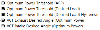
The one exception to this strategy which occurs when the "Optimum Power" (OP) mode is active.
When conditions are met to activate VCT OP mode, the VCT angles will be reflective of their desired angle calibration settings. When not in OP mode, the ECU will attempt to run in Fuel Efficiency or other modes and will vary VCT angles to achieve the most desirable result.
Most of the vehicles which we support have by default disabled weighting for the OP tables. We highly recommend taking the time to adjust and verify the tables associated with each VCT mapped pair for best results. This can be done by using the VCT Manual Mode toggle, and setting the VCT Exhaust/Intake Target (Manual Mode) values to match a specific table pairing.
Volumetric Efficiency
What is Volumetric Efficiency (VE)?
In simple terms, VE is the measured ability of an engine to move an air charge in and out of its cylinders. VE is often measured as a ratio or percentage. For the intent of this document and our software we will reference percentages. Normally aspirated motors will often struggle to achieve 100% VE, while an efficient forced induction engine will often exceed 100% for most of its boosted power-band.
How does Ford calculate VE?
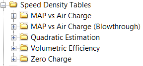
Ford has devised a model to calculate, estimate, monitor, and react to VE changes through various iterations of the slope-intercept linear equation (y=mx+b). The slope (m) is represented by values in the MAP vs Air Charge folder. The intercept (b) is represented by values in the Zero Charge folder. The equation uses Manifold Air Pressure (MAP) for ( x ) and results with ( y ) as Aircharge mass.
This value only gets us halfway there. We still need to know the inlet density to calculate VE. This is where the Ford mathematicians went to town through a series of advanced algorithms. They came up with a method to calculate dry air density, and single cylinder displacement for any engine size. By providing the displacement of the engine in liters, the number of cylinders, and the current MAP, the ECU can calculate inlet density.
Unfortunately, all of this math is done in background processes in the ECU, manipulated for specific uses, and is never stored for monitoring at the moment we need it. That wasn't going to stop us from extracting this important calibration data. We have injected custom code to generate data monitors which allow real-time viewing of the modeled VE, and VE for the currently measured aircharge.
Why is this data important?
This model is responsible for measuring inputs from the MAP/TIP/Baro sensors and translating them into aircharge, load, airflow, torque, and other governable unit types. The accuracy of this translation is extremely important to ensure all of the dependent models are fed with relevant data. These dependent models include but are not limited to Fuel, Timing, Boost, Wastegate, Torque, and Airflow. The ECU can correct for discrepancies against the model up to an extent. However, it is best practice to re-calibrate the core VE model when components are replaced that can change the actual VE of the motor. This includes components such as an intake, exhaust, turbocharger, camshafts, headwork, and pistons.
How do I ensure my VE model is accurate?
As mentioned earlier, we've added some new monitors to make this portion of calibration less painful. We've also put together a handy VE spreadsheet to use as a tuning aid. Check the resources section at the end of this document for a link to access this spreadsheet. Let's go over one of the strategies that can be used to quickly dial in your VE curves.
Calibrating VE
Gathering Data
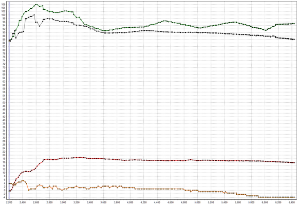
We first need a good baseline of data to determine the scope of potential changes. This is done by logging a few WOT pulls with specific monitors over the entire operating range (~1500-6800rpm).
You'll want the following monitors at minimum: (C) Estimated VE Model Corrected, (C) Estimated VE Actual Corrected, Actual AFR, Boost Pressure, Commanded EQ Ratio, Engine Speed, Load Actual, Long Term Fuel Trim,Short Term Fuel Trim, VCT Exhaust Angle Actual, VCT Intake Angle Actual
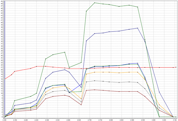
The resultant data will allow you to visualize the VE curve of the engine and determine if there are areas in need of improvement. This is done by analyzing the STFT/LTFT corrections against the delta between Modeled VE and Actual VE.
Making Changes to the VE Curve
If the STFT+LTFT value is positive it means the ECU is not commanding enough fuel and therefore needs additional VE. For this example, we will assume that the total correction amount at 2500rpm is +15% and it tapers to 0% by 5000rpm. Let's also assume that we know based on the HDFX reference table that between 2500-5000rpm we're utilizing 100% of Table 06. This means we'll want to make changes to the Slope of MAP vs Air Charge (Table 06) to resolve the inaccuracy.
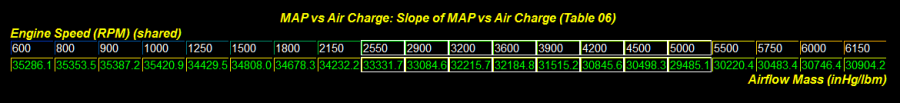
To increase VE subtract values, to decrease VE add values. We would multiply the value at ~2500rpm by 0.85 to increase VE by 15%, and continually decrease that trend towards 5000rpm. Use the table graph as a visual means to keep the overall table as smooth as possible. If other tables were actively weighted, make similar percentage changes to the same areas before performing your next reflash.
Caution - Changing VE will directly affect the calculation of load and airflow. This may require additional changes to ensure anything that is indexed with these unit types is accommodated for.
Repeat this process until your total corrections are within +/- 5% for best results.
Advanced VE Tuning
There are more advanced methods to calibrate VE once the basic concepts above have been exercised and familiarity on the process grows. We introduced you to HDFX earlier and now it's time to apply those resources. We will now demonstrate how to fine tune a single HDFX VE table. Once again you'll need a few WOT pulls with specific monitors over the entire operating range (~1500-6800rpm).
To determine which HDFX VE table is being used monitor the following: HDFX Weight Table (ALL), (C) Estimated VE Model, (C) Estimated VE Actual Corrected, Actual AFR, Boost Pressure, Comm. EQ Ratio, Engine Speed, Long Term Fuel Trim, Short Term Fuel Trim, VCT Exhaust Angle Actual, VCT Intake Angle Actual, VE Correction Ratio
The resultant data will allow pinpointing of a particular table for fine tuning. In this example we'll begin with Table 14. From the reference table used earlier we can determine the VCT pair is -18°i, 22°e. Now it's time to lock the cams and dial in this table.
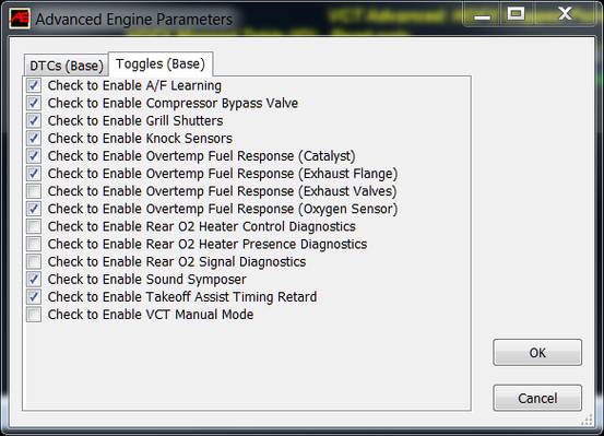
Start by enabling VCT Manual Mode in the toggles (CTRL+A). Follow this by changing the VCT Exhaust/Intake (Manual Mode) values to the Table 14 references (-18°i, 22°e).
Now that the cams are locked, a new series of data can be collected to continue.
You'll want the following monitors at minimum: (C) Estimated VE Model, (C) Estimated VE Actual Corrected, Actual AFR, Boost Pressure, Commanded EQ Ratio, Engine Speed, Load Actual, Long Term Fuel Trim, Short Term Fuel Trim, VE Correction Ratio
The goal here is to adjust one table at a time to ensure the VE model is accurate. This method can also be utilized for the remainder of VCT pairs to ensure accuracy under all camshaft angles. It's also going to be a great time to open up that COBB VE Tuning Aid to visualize how your changes will look before applying them. The spreadsheet will allow you to visualize the result of higher pressures without having to stress the engine.
Pro-Tip
After correcting the VE model, take advantage of this time to adjust ignition timing, torque to load, and any other group of HDFX tables associated with each VCT pair.
Using the COBB VE Tuning Aid
There are several input fields available to allow the ease of copying and pasting values from Accesstuner software. See the legend for the color representation of these fields. The default values are configured for a 2.0L Ecoboost Focus ST but can be swapped easily for any engine. We have included values for a few popular vehicles. The OEM slope-intercept values have been supplied for these vehicles on the HDFX References tab. For this example we'll stick with the Focus ST defaults.

First we'll choose a VCT pair for review and populate the slope and offset values. If starting from scratch, use the HDFX References tab and "paste values" to retain formatting. If you have already modified values in your calibration, simply copy and paste them from Accesstuner. The VE data will auto-populate below, along several other conversions further down.
- COBB VE Tuning Aid - COBB_Ford_VE_Tuning_Aid.xlsx
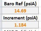
Next, input Barometric Pressure. This can be obtained by using the Accessport. The final step is to select a pressure increment for the graph. This will allow fine or coarse granularity for the charts below. We've placed a conversion reference for Boost Pressure and MAP on the primary axis to aid in the process.

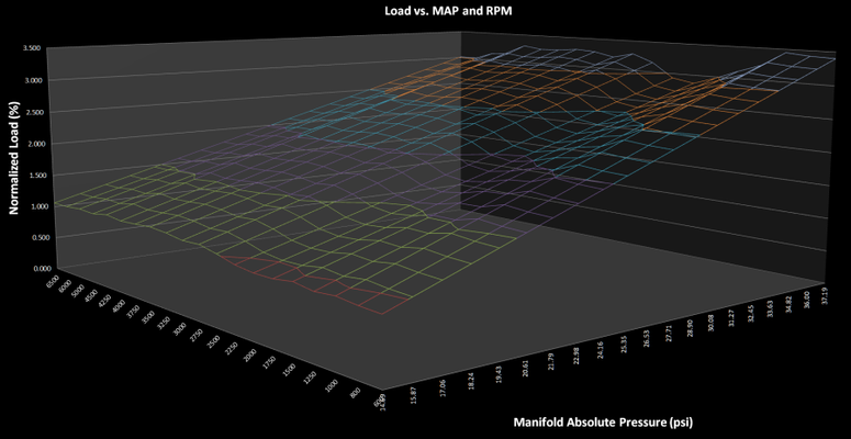
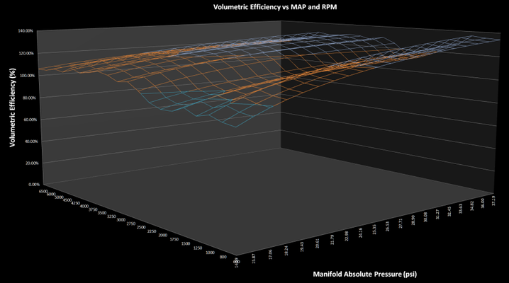
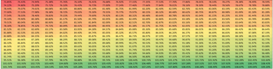
Now that the basic inputs have been entered the VE model can be viewed in all of its 3D glory! Additionally you'll find charts that represent Aircharge, Load, and Pressure throughout the spreadsheet. Make changes as needed to the slope and intercept values to obtain a desired VE curve. Once changes are complete, simply copy and paste these values back into Accesstuner and gather new data.
Reference Material
Links
Engine & Transmission Monitor List for Ford Vehicles
Accesstuner Software & Feature Support
COBB Tuning Customer Support Center
Reference Material
U.S. Patent Number 5357932A – Fuel control method and system for engine with variable cam timing
U.S. Patent Number 6115664A – Method of estimating engine charge
U.S. Patent Number 6850831B2 – Method and system for estimating cylinder charge for internal combustion engines having variable valve timing
U.S. Patent Number 6851304B2 – Air estimation approach for internal combustion engine control
U.S. Patent Number 7380447B2 – Method and system for transient airflow compensation in an internal combustion engine
The Big Orange Heavy Thing – Injector Dynamics
Customer Support
Phone support available 9am to 6pm Monday-Thursday. 9am to 4pm Friday (CST)
866.922.3059
Related content
Copyright 2025 © COBB Tuning Products LLC. All Rights Reserved. | www.cobbtuning.com