EcoBoost Wastegate Strategy Addendum
- Will Trang

![]()
EcoBoost Wastegate Strategy Addendum
The WG Actuator Canister Pressure Control System
Date Revised: 2/2/2016
Starting with smaller displacement engines such as the 1.5L and 1.6L in MY13, Ford introduced a new way to control boost pressure on the EcoBoost platform. Newer model years and larger engines have also adopted this strategy as it offers more precise control of the turbocharger based on feedback from pressure created and consumed. This new control strategy is designed to regulate boost by providing either pressure or vacuum to the turbocharger's wastegate actuator canister. The delivery is done through one or more solenoids and can be configurable through switches in the event that an actuator is replaced with an aftermarket unit. This wastegate control model was designed to be feed-forward based. This means that a base target is set and the wastegate control PID system attempts to achieve the base target through continuous feedback and prediction.
Turbocharger boost pressure is the main variable used to create engine torque. When a load or torque increase is desired by the driver, the ECU will look to the turbo and wastegate models to achieve specific power output accordingly. Increasing load or torque target values will allow the vehicle to create more boost (airflow) as long as the appropriate limit tables are raised.
This system adds a lot of background complexity, but ends up being quite simple to dial in due to the self-regulating properties of the system. Instead of applying dynamics to the wastegate duty cycle, they are applied directly to the WG Actuator Canister Pressure (X-Axis) of the WGDC Base table!
Coarse Adjustment When Under Or Overboosting

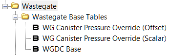
WGDC Base
This is the primary wastegate table the ECU uses for boost control. This table is referenced by WG Actuator Canister Pressure on the X-Axis and Compressor Outlet Pressure (Relative) on the Y-Axis. The Z-data (table data) is direct wastegate duty cycle %. Depending on application, there may be additional compensations applied to the final calculation of WGDC.
Take a moment to study the characteristics of this table as it will help immensely when beginning calibration of the wastegate model. As compressor outlet pressure increases, so should the amount of pressure going to the WG actuator. However, since we do not want the actuator to see true pressure and crack wide open, portions of it are bled off to allow boost pressure to rise due to the actuator keeping the flapper closed. This is why values on the left side near the 0psi point are high and at higher "visible" pressures the WGDC is much lower.
Dialing in this table can take a bit of time but is made easier by the available "override" tables on certain applications. The X-Axis is regulated by a feed-forward PID system which uses the WG Canister Pressure Desired (FF) Non 5-Way table as a base to drive control.
- Pro Tip: To make things easier when dialing in wastegate control the X-Axis on the WGDC Base table can be "forced" to any value. To do this simply set the WG Canister Pressure Override (Offset) to the value desired and the WG Canister Pressure Override (Scalar) to 0.0. Then, dial in the required wastegate to achieve load or torque targets for each pressure delta column. Once complete, set the override values back to stock and test the new table through various gears and RPM.
Note: Adding more wastegate duty cycle than the system needs can result in an overboost condition which will cause the ECU to take alternative measures to control boost, such as using major throttle closures, fuel cut, or going into limp mode.
Fine Adjustment Using The PID Controls
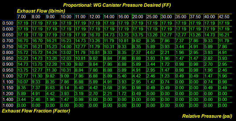
WG Canister Pressure Desired (FF) Non 5-Way
This is the base table used for predicting wastegate actuator canister delta pressure as generated by the turbo wastegate controls. The OEM settings work well at stock boost levels, but can quickly become unfavorable as boost is raised. Making changes to this table will result in a direct change in the lookup behavior of the X-Axis for the WGDC Base table. The lookup value from this table is then added to the current Barometric Pressure to create the base P-Term of the PID. This can be monitored using the WG Canister Pressure Base monitor. The final P-Term can be monitored using the custom WGDC P-Term monitor.
The table is referenced by Exhaust Mass Flow Est. on the X-Axis and Exhaust Flow Fraction on the Y-Axis. The Z-data (table data) is Wastegate Canister Pressure Desired (Relative).
Changes to this table are recommended when the shape of the boost or TIP curves are undesirable for the desired load or torque. If the Boost Pressure or TIP Actual is too high, raising these values will push WG Canister Pressure higher (removes WGDC). If the Boost Pressure or TIP Actual values are low, lowering these values will push WG Canister Pressure lower (adds WGDC).
See our Off-The-Shelf maps for an example of how we adjust these tables for more consistent results with little to no throttle closures.
Adjusting and monitoring wastegate performance (Non 5-Way)
Add Boost Pressure Actual, Exhaust Mass Flow Est., WGDC Actual, WG Canister Pressure, WGDC Y-COP Relative, and WGDC Y-Factor to your logging profile. These are the primary components to properly tune the wastegate PID system. If needed remove other unused monitors from your logging profile to make room.
The first thing you'll need to do is collect a datalog of your vehicle with these monitors included. We recommend tuning the car in 4th gear for best overall results. Our recommended recording window is from 2000-6500rpm.* This will provide an ample sweep of the WGDC Y-Factor and Exhaust Mass Flow Est. to begin coarse modification to the WG Canister Pressure Desired (FF) Non 5-Way table.
Once the data is collected, review the log for problem areas in need of adjustment. Find the cell that matches, and highlight adjacent cells as well if needed (the ECU will "blend" several cells to get final values). Make small incremental changes to the base table then re-flash and re-log. The goal is to find a happy medium of the WGDC Base values and WG Canister Pressure Desired (FF) Non 5-Way values such that the desired boost pressures are achieved in all conditions!
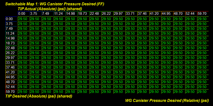
WG Canister Pressure Desired (FF) 5-Way
This is the COBB base table used for predicting wastegate actuator canister delta pressure as generated by the turbo wastegate controls. The OEM settings work well at stock boost levels, but can quickly become unfavorable as boost is raised. Making changes to this table will result in a direct change in the lookup behavior of the X-Axis for the WGDC Base table. The lookup value from this table is then added to the current Barometric Pressure to create the base P-Term of the PID. This can be monitored using the (C) WG Canister Pressure Base monitor. The final P-Term can be monitored using the custom WGDC P-Term monitor.
The table is referenced by TIP Actual on the X-Axis and TIP Desired on the Y-Axis. The Z-data (table data) is Wastegate Canister Pressure Desired (Relative).
Changes to this table are recommended when the shape of the boost or TIP curves are undesirable for the desired load or torque. If the Boost Pressure or TIP Actual is too high, raising these values will push WG Canister Pressure higher (removes WGDC). If the Boost Pressure or TIP Actual values are low, lowering these values will push WG Canister Pressure lower (adds WGDC).
- Pro Tip: To make things easier when creating a calibration using this table, add the OEM WG Canister Pressure Base monitor and subtract Barometric Pressure. Then fill in the table for each breakpoint that lines up with TIP Desired and TIP Actual. This will result in a very rough, but usable base table!
Adjusting and monitoring wastegate performance (5-Way)
Add Boost Pressure Actual, TIP Desired, TIP Actual, WGDC Actual, WG Canister Pressure, and WGDC Y-COP Relative to your logging profile. These are the primary components to properly tune the wastegate PID system in this configuration. If needed remove other unused monitors from your logging profile to make room.
The first thing you'll need to do is collect a datalog of your vehicle with these monitors included. We recommend tuning the car in 4th gear for best overall results. Our recommended recording window is from 2000-6500rpm.* This will provide an ample sweep of the TIP Desired and TIP Actual to begin coarse modification to the WG Canister Pressure Desired (FF) 5-Way table.
Once the data is collected, review the log for problem areas in need of adjustment. Find the cell that matches, and highlight adjacent cells as well if needed (the ECU will "blend" several cells to get final values). Make small incremental changes to the base table then re-flash and re-log. The goal is to find a happy medium of the WGDC Base values and WG Canister Pressure Desired (FF) 5-Way values such that the desired boost pressures are achieved in all conditions!
Additionally, there are upper and lower ceilings for the final calculation of the PID I-Term which can be used to loosen or tighten the reigns of the system if necessary. These are found in the Integral folder and are labeled PID I-Term Max. and PID I-Term Min..
Throttle Closures From Overboosting
Throttle closures can be a result of running boost pressures higher than set in the TIP Desired Max. (Ceiling) table. These throttle closures can be seen in the log as a deviation between the Accelerator Pedal Position value and ETC Angle Actual. Accelerator Pedal Position should read ~99% when at wide open throttle and ETC Angle Actual should read ~82%.
*Note: Starting from different gears and RPM will change the sweep of the curves and will take some fine tuning to achieve a smooth boost curve for all gears and starting points
Related content
Copyright 2025 © COBB Tuning Products LLC. All Rights Reserved. | www.cobbtuning.com