Ford Tuning Guide
- Will Trang
- Brandyn Mowat

![]()
Version: 2.05
2/04/2016

ADM/EDM/USDM Ford Focus ST (C346ST and C346ST MCA)

USDM Ford Fiesta ST (B299ST)

USDM Ford Fusion (1.6L/2.0L EcoBoost) (CD391N)

USDM Ford Mustang (2.3L EcoBoost) (S550)
Getting to know Ford
Here we will go over a few of the basic details and terminologies that are specific to Ford before we begin tuning on a COBB Accessport equipped Ford Ecoboost vehicle.
MAP Based – These vehicles use a MAP based airflow system. This is also known as Speed Density. While some Ecoboost vehicles do have a MAF sensor in place, it is not used for airflow calculations.
Throttle Closures – The primary method of controlling torque on these cars is done with the assistance of the drive-by-wire throttle system (factory tune). The factory tune allows the throttle to close to less than 20% (of the 82% max) which can result in extremely consistent torque delivery, but neutered performance. There are two main offenders that will result in throttle closures: Load and Boost. We recommend adjusting these limits higher to take full control of the throttle. See our OTS maps for effective examples.
Fuel Control – Ecoboost engines operate in a constant closed-loop state, constantly utilizing the A/F values in its tables and making adjustments via its equipped wide-band O2 sensor. While certain tables are marked as "Open Loop", they are labeled as such to distinguish the difference between stoichiometric operation and air fuel targets during power enrichment (such as wide open throttle).
Boost Control – These vehicles do not directly target boost in stock form but rather engine torque. Engine torque is calculated based on numerous variables such as: pedal position, air flow, boost and RPM.
Ignition Control – The Ford ECU has an incredibly complex timing strategy. It consists of four primary methods to control spark: MBT, Borderline, Cylinder Pressure, and Pre-Ignition. The ECU also allows full dynamic advance and retard based on octane learning and knock sensor feedback. There are up to 16 primary tables for each method, along with accompanying compensations. All of these must be touched to produce desired results. To see a good example of an effective timing strategy, compare and contrast a few of our various OTS maps.
"5D" 3D Tables – The Ford ECU uses a new style of 2D axes in select 3D tables. In these tables both the X and Y axis have "paired" data. On tables that would require it, we have broken these out for editing in separate folders. The axes are generally index based and may require manipulation to both the index and/or the data to properly display graphs or to utilize greater breakpoint resolution.
Over-temp Conditions – There are numerous watchdogs in the ECU that can put the car into an over-temp mode. During this mode, additional fuel is injected in an attempt to cool the car down and bring conditions back to normal. This will result in poor performance and use excessive fuel. Care should be taken to adjust these temperatures with the appropriate sensors in place to ensure optimal power delivery and engine safety are achieved.
Commonly Used Acronyms
|
|
The Tuning Guide
This tuning guide is broken into the basic components of tuning an Ecoboost vehicle and the tables associated with each of these components. For each major tuning category, the guide outlines basic tuning strategies and defines tables within this category (for example: Boost Control, Fueling, and Ignition Timing). Table descriptions and tips are available in the table description window of Accesstuner software.
Step 1 – What is the mechanical configuration of the vehicle?
The first step in tuning these vehicles is choosing a COBB Tuning Off-The-Shelf (OTS) calibration that most closely matches the mechanical components and modifications of the vehicle to be tuned.
The Stage1 calibrations are designed for vehicles with an all stock configuration. The Stage1 COBB mapping was designed with optimized ignition, boost, and fuel targets for enhanced performance and responsiveness on a vehicle with mainly stock hardware.
The Stage2 calibrations are generally designed for vehicles equipped with an upgraded front mount intercooler, and upgraded intake system. The Stage2 COBB mapping was designed with optimized ignition, boost, and fuel targets for enhanced performance and responsiveness on vehicles with upgraded front mount intercooler hardware.
The Stage3 calibrations are generally designed for vehicles equipped with an upgraded front mount intercooler, full turbo back exhaust and an upgraded intake system. The COBB Stage3 mapping was designed with optimized ignition, boost, VCT, and fuel targets for enhanced performance and responsiveness for vehicles equipped with "FBO".
Step 2 – What fuel is the vehicle using?
Please note that COBB Tuning offers select performance calibrations for three different fuels: 93 octane (98 RON), 91 octane (95 RON) and 87 (89 RON). ACN91 octane from Arizona, California, or Nevada is compatible with our 91 octane calibrations. If your fuel does not meet the standard of the available COBB maps you will need to adjust the calibration accordingly. Take a moment to compare and contrast timing, boost, and ignition tables from each type of calibration. Higher octane fuels support more ignition timing, higher boost levels, and leaner air to fuel mixtures compared to lower octane. Using a map designed for high-octane with low-octane fuels may result in engine damage.
Step 3 – What type of air intake is on the vehicle?
These vehicles utilize manifold absolute pressure (MAP) sensors located pre and post throttle body to measure the mass of air entering the engine. Filter configuration does not necessarily require tuning but heavily contaminated air filters of both OEM and aftermarket construction were found to reduce power output at moderate to high engine speeds. Frequent air filter cleaning and/or replacement is recommended for best performance and engine protection.
Preparing to calibrate the vehicle
Connect the Accesstuner software to the Accessport equipped vehicle
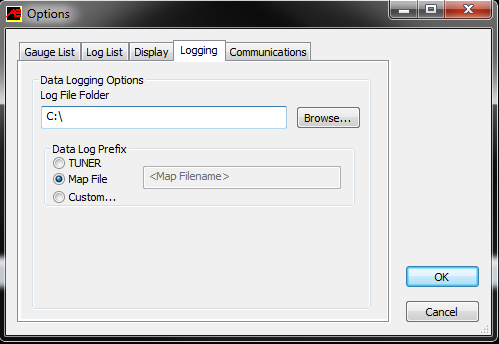
Open the selected starting point calibration in the Accesstuner software. Configure the Accesstuner software to connect to your vehicle. Attach the OBDII cable to the vehicle and the associated USB to the computer and Accessport. Press "Ctrl+F" to configure the program. Select the directory in which to store your data logs under the "logging" tab.
Display and Log critical engine parameters while testing
Accesstuner software allows the user to visualize, sample and record critical engine parameters including sensor information and commanded engine function.
To configure displayed parameters on the live "Dashboard" press "Ctrl+F" to configure the logged parameters in the "Log List" tab, and those displayed in the Accesstuner "Dashboard" through the "Gauge List" tab. The Dashboard, a screen that reports active engine and sensor parameters, can be accessed by pressing "Ctrl+B." It is critical to actively monitor the condition of the motor during tuning and this screen is the single best way to do so. These data monitors allow the tuner to determine if a calibration is performing correctly. Accurate and deliberate assessment of logged parameters is the only way to avoid conditions that may damage the motor.
Hint: Configure recorded parameters in the "Log List" tab
While connected to a running vehicle press "Ctrl+F" and select the "Log List" tab to select the parameters displayed in saved Accesstuner logs. When data logging is enabled (Ctrl-D) these parameters will be permanently written to a comma delimited data file.
Note: Using more than 20 parameters at any given time may result in the rate of data collection to be lower than optimal. For example, you will see a higher sample rate with 12 parameters than 20 parameters.
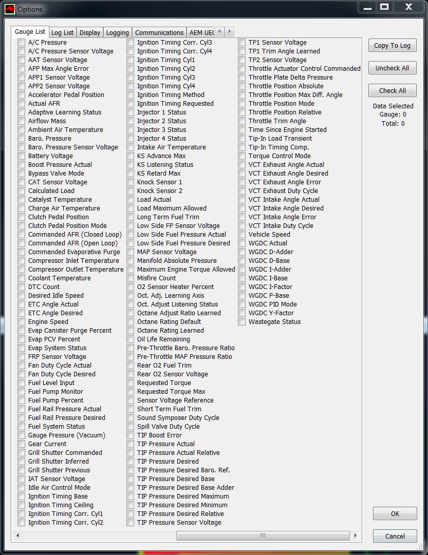
This is a screen shot of some of the available parameters to display in the live dashboard gauges (Gauge List tab) or to be recorded in the data log file (Log List tab). Latest monitors can be found in the Engine & Transmission Monitor List for Ford Vehicles document.
Below is a list of some recommended parameters for these vehicles. The selected parameters are those that are critical to record under most conditions. Other parameters may be selected or removed based upon the objectives of any specific tuning process.
- Accelerator Pedal Position – The percent of pedal movement at the driver's foot.
- Actual AFR – The lambda reading from the internal wide-band oxygen sensor (Front).
- Airflow Mass – The amount of air moving through the engine.
- Boost Pressure Actual – Boost as measured in relative form inside of the intake manifold.
- Charge Air Temp. – (CAT) Charge air temperature as measured post intercooler, before the throttle body.
- Coolant Temperature – Engine coolant temperature.
- Engine Speed – Engine speed in revolutions per minute (RPM).
- ETC Actual Angle – This is the final actual throttle angle including all compensations and trims.
- Fuel Rail Pressure Actual – The fuel pressure as measured in the fuel rail.
- Ignition Timing Corr. Cyl (1-4) – Individual cylinder timing correction in degrees (+/-).
- Ignition Timing Cyl (1-4) – This is the final actual ignition timing after all correction and adjustments in degrees before TDC.
- Load Actual – This is actual calculated engine load value (absolute).
- WGDC Actual – This is the final wastegate solenoid duty cycle after PID system compensations.
- STFT – Short term fuel trims displayed in percent. (See LTFT for description)
- LTFT – Long term fuel trims displayed in percent.
Calibration Refinement (Using a Load-Based Chassis Dynamometer)
A: Perform initial testing at lower boost
After choosing the most appropriate starting point calibration, prepare to test and refine the calibration on a load-based chassis dynamometer. When creating a custom tune, it is best to begin testing under low load and boost conditions by lowering values from the "TIP Desired Max. (Ceiling) Non 5-Way" table. This will lower the maximum allowed throttle inlet pressure. Testing done at lower boost will allow you to assess the calibration without putting the motor under potentially dangerous conditions. Start the tuning process by loading this "low boost" starting point calibration onto the vehicle.
B: Increasing boost targets
The Ecoboost ECU is torque and load based, meaning it uses a complex routine to look at several tables based on conditions to achieve its target torque utilizing a dynamic boost level. (Barometric Pressure, Ambient Temp, Charge Air Temp. Etc...)
There are many limits and targets surrounding torque and these are what are typically manipulated in order increase horsepower and torque. The main controls for the boost system are in the "Boost Control Tables" folder. You will raise many of these values to increase boost as you begin tuning. You will need to utilize the wastegate parameters to keep the system "in-check". The wastegate duty cycle controls on the EcoBoost engine is PID controlled. Making large or incorrect adjustments to the wastegate system can result in throttle closures (over-boosting) or under-boosting. We will go into wastegate control in just a moment.
Creating the minimum, maximum, and desired pressure variables
To create the TIP Desired Minimum, you simply need to leave the TIP Desired Minimum (Spring Pressure) table alone, or adjust it for any changes that have been made to the wastegate actuator. This table is referenced by Airflow Mass, the table values are relative pressure and are added to Barometric Pressure to become absolute for the calculations. This table may need adjustment when using aftermarket bypass valves or components to ensure proper operation.
To create the TIP Desired Maximum, you simply need to come up with a pre-determined boost pressure (absolute) ceiling and apply it to the TIP Desired Max. (Ceiling) Non 5-Way table. Above this value the ECU will close the throttle to keep boost under this ceiling.
To create TIP Desired Absolute please reference the boost target logic diagram below:
The boost target strategy decision logic
(Monitor Name) TIP Desired Minimum Barometric Pressure + TIP Desired Minimum (Offset) | (Monitor Name) TIP Desired Absolute Manifold Absolute Pressure + Throttle Plate Delta Pressure* | (Monitor Name) TIP Desired Maximum TIP Desired Max. (Ceiling) |
The boost target strategy post-decision "sandwich" logic
(Monitor Name) TIP Desired Minimum → | (Monitor Name) TIP Actual Absolute | (Monitor Name) ←TIP Desired Maximum |
*Throttle Plate Delta Pressure or TPDP is created with the following set of variables:
The ECU will attempt to ride in between the Minimum and the Maximum using TIP Desired. If TIP Actual falls below the Minimum, the wastegate PID will attempt to add WGDC to bring pressure up over the minimum. If TIP Actual goes above the Maximum, the ECU will attempt to control boost by closing the throttle.
Note: Low values in the LSPI tables can OVERRIDE the TIP Desired Minimum.
We create this method by raising tables that could otherwise affect the target by manipulating the TIP Desired Absolute. We recommend using one of our OTS maps as a base to maintain this method, but if you were to use alternate methods, some of the tables we recommend modifying are:
- Low Speed Pre-Ignition Load Limit (Low, Mid, High)
- Pressure Drop Estimate (High Pressure System)
- Pressure Drop Estimate (Low Pressure System)
- TIP Actual Max. (Airflow Based)
- MAP Limit (Combustion Stability)
- COT Limit (Low, Medium, Infinite Duration)
- Overboost & Underboost Thresholds
In order to gain an understating of the ECU's current boost control operation you should monitor the following parameters (these pressures are Absolute, and pre-throttle):
- "TIP Desired Minimum" (to determine the pressure minimum)
- "TIP Desired Maximum" (to determine the pressure maximum before throttle closures)
- "TIP Desired Absolute" (to see the final requested pressure)
- "TIP Actual Absolute" (to see the actual pressure)
The ECU will not always hit the pressure target as it will only utilize as much pressure as necessary to achieve the load or torque targets. Some deviation between TIP Desired Absolute and TIP Actual Absolute is not uncommon or necessarily sign of problems. To see the current relative "gauge" pressure as measured in the intake manifold we recommend monitoring Boost Pressure Actual.
C: Wastegate PID System and Adjustments (older airflow based strategy)*
*for the newer canister pressure strategy see our EcoBoost Wastegate Strategy Addendum
The turbocharger boost levels are the main variable used to create torque. When you increase your boost targets, you will see the ECU generally needs more Wastegate Duty Cycle (%) in order to achieve the higher boost levels. Increasing boost target values will allow the vehicle to create more boost (within the systems limits) as long as the corresponding limit tables are raised.
Coarse adjustment when underboosting
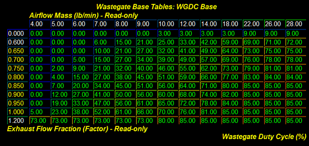
WGDC Base – This is the primary wastegate table the ECU uses for boost control. This table is referenced by Airflow Mass on the X-Axis and WGDC Y-Factor (a fraction of desired turbine power) on the Y-Axis. The Z-data (table data) is direct wastegate duty cycle %. These values are the base WGDC % before wastegate PID systems become active and attempt to further control boost. Adjusting the main table is mostly used for large boost targeting corrections, adding or removing small amounts should be left to the WGDC Dynamics. Adding more wastegate duty cycle than the system needs can result in an overboost condition which will cause the ECU to take alternative measures to control boost, such as using major throttle closures, fuel cut, or going into limp mode.
 |  |
Fine adjustment using the PID Controls
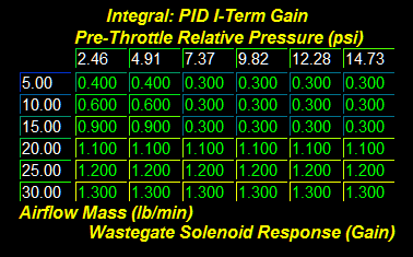
PID I-Term Gain – This is the base value for the "quick" response portion of the PID. This table is referenced by TIP Actual Relative on the X-Axis and Airflow Mass on the Y-Axis. The Z-data (table data) is wastegate solenoid response gain. The factory settings are a bit aggressive, so we recommend dialing these base values back a bit so the portion of this PID is less effective. See our OTS maps for an example of how we adjust this table.
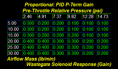
PID P-Term Gain – This is the base value for the "continuous" response portion of the PID. This table is referenced by TIP Actual Relative on the X-Axis and Airflow Mass on the Y-Axis. The Z-data (table data) is wastegate solenoid response gain. The factory settings are a bit lethargic, so we recommend bumping these base values up a bit so the portion of this PID is more effective. See our OTS maps for an example of how we adjust this table.
PID I-Term (Max) – This is the primary table the ECU uses for positive WGDC corrections. This table is referenced by Airflow Mass and Z-data is the maximum WGDC % that can be added when the boost target is not achieved. Setting the values in here can increase, or decrease the maximum amount of WGDC achieved. Reference our OTS maps for a good example of this table's use.
Throttle Closures From Overboosting
Throttle closures can be a result of running boost pressures higher than set in the TIP Desired Max. (Ceiling) Non 5-Way table. These throttle closures can be seen in the log as a deviation between the Accelerator Pedal Position value and ETC Angle Actual. Accelerator Pedal Position should read ~99% when at wide open throttle and ETC Angle Actual should read ~82%.
Adjusting and monitoring wastegate performance
Add Boost Pressure Actual, WGDC Y-Factor, WGDC Base, WGDC P-Term, and WGDC I-Term to your logging profile. These are the primary components to properly tune the wastegate PID system. If needed remove other unused monitors from your logging profile to make room. Once these monitors are added, collect a log where throttle closures can be seen.
The first thing you'll need to do is collect a datalog of your vehicle with these monitors included. We recommend tuning the car in 4th gear for best overall results. Our recommended recording window is from 2000-6500rpm. This will provide an ample sweep of the WGDC Y-Factor and Airflow Mass to begin coarse modification to the WGDC Base table.* Once the data is collected, review the log for problem areas in need of adjustment. Find the cell that matches, and highlight adjacent cells as well if needed (the ECU will "blend" several cells to get final values). Lower the values in a problem area to correct overboost conditions, or raise them to correct underboost conditions. Make small incremental changes to the base table then re-flash and re-log. Keep a watchful eye on the WGDC I-Term values and adjust the PID I-Term (Max) table as needed to avoid utilizing too much dynamic correction. The goal is to find a happy medium of the Base values and Dynamic values such that the desired boost pressures are achieved in all conditions!
D: Tuning for appropriate Air to Fuel ratios (Lambda)
The ideal air to fuel ratio depends upon fuel quality. Higher octane fuels are more detonation resistant and therefore can be run at leaner air to fuel ratios. Leaner Air to Fuel ratios produce higher power but also create more heat. Excessive heat can lead to detonation. Lower octane fuels such as 91 octane (95 RON) are more prone to detonation and therefore generally require a richer air to fuel ratio. Rich air to fuel ratio combustion produces less heat and therefore less detonation.
These vehicles utilize an internal wide-band oxygen sensor to monitor fuel mixtures. The sensor is located in the down pipe. The target values for the Air to Fuel mixture can be monitored using the following, Commanded EQ Ratio and Desired AFR (PD). The currently measured air to fuel mixture can be seen using the Actual AFR or Actual AFR (SP) monitors. The adaptive adjustments made by the ECU are monitored using Short Term Fuel Trim and Long Term Fuel Trim. The adaptive adjustments run full time in a closed-loop PID system.
The primary means to adjust fueling during WOT conditions is with the Desired Fuel Target (Power Demand) table. This table is referenced by ECT and Engine Speed. The targets in this table are used by the ECU to set the desired AFR (Lambda). The threshold for utilizing this table is determined by Accelerator Pedal Position input and is named Power Demand Threshold (APP). Under this threshold the car will run in Closed-Loop and attempt to achieve the Fuel Scalar Stoich. Setpoint.
E: Tuning for appropriate Spark Advance
The Ford Ignition Timing Strategy
The timing strategy in this ECU is extremely complex and robust. We highly recommend using one of our OTS maps as a base when beginning to tune. Below you will find a general overview of the ignition timing strategy and how it can be manipulated to ease tuning. Most of these tables are referenced by Engine Speed and Load Actual. Logging these parameters will allow you to reference the specific regions of these tables that may need to be edited to produce optimized ignition timing.
The ignition timing strategy decision logic
(Monitor Name) Spark Limit Source (+Corresponding Compensations) | (Monitor Name) Ignition Timing Base +Avg. of Timing Corr. Cyl 1-4 | (Monitor Name) Ignition Timing Requested This is the final requested timing target. |
1 = MBT Timing (MBT)
2 = Borderline Timing (BL)
4 = Pre-Ignition Timing (PRE)
5 = Cylinder Pressure Timing (CYL)
The ignition timing strategy post-decision "sandwich" logic
(Monitor Name) Ignition Timing Base Lowest of MBT, PRE, or CYL. | → | (Monitor Name) Ignition Timing Cyl 1-4 +/- Ignition Timing Corr. Cyl 1-4 | ← | (Monitor Name) Ignition Timing Ceiling Lowest of MBT, BL, PRE, CYL. |
Knock Sensor Dynamic Feedback
Ignition timing is also adjusted in response to detonation. The ECU can actively increase and reduce timing in response to detonation (or lack thereof). The ECU has the capability to make individual cylinder timing adjustments. This means that monitoring a single cylinder for timing correction will not result in a global picture of engine operations. Timing adjustments are logged with the "Ignition Timing Corr. Cyl 1-4" monitor. The amount of timing subtracted during knocking conditions can be adjusted with the "Knock Sensor Timing Decrement (Retard)" table. During non-knocking conditions, the ECU will attempt adjust timing in small increments up to the maximum value in the table "Knock Sensor Timing Max. (Advance)" or the delta of the Ignition Timing Ceiling and Ignition Timing Base tables; whichever is lower.
Ignition Timing Compensations
Ignition timing compensations exist for each timing method except for the Pre-Ignition Timing Limit (Ceiling). Be mindful of the total value of each group of compensations when developing a desired timing curve. Since the ECU chooses the lowest of these tables, various compensations could push one table higher than others and drastically change the base or ceiling chosen.
Ignition Timing General Guidelines
Generally speaking, higher ignition timing supports higher torque and greater power. However, ignition timing should be increased with great caution. Higher timing yields higher cylinder pressures and this is limited by fuel quality and mechanical limitations of the engine. Too much timing will produce negative knock corrections when fuel quality is limiting. When fuel quality is high, ignition timing should ONLY be added when its addition produces a substantive increase in torque and power. If increased timing does not increase torque the extra cylinder pressure is simply producing unnecessary stress on engine components.
F: Tuning Ti-VCT (Variable Camshaft Timing)
The VCT operation of this car is well optimized from the factory for the stock turbo. The COBB off the shelf maps are designed with slightly modified camshaft phasing to further optimize performance for stock turbo chargers, stock camshafts, and stock motor internals. We have designed the COBB mapping to enhance turbo responsiveness and midrange torque. These maps may need to be altered considerably for larger turbocharger, or aftermarket engine components. Also note that changing VCT may require changes to the Speed Density Tables to ensure accurate calculations.
G: Integrating all tuning parameters for the ideal Calibration
The ideal calibration for your vehicle is a combination of all major tuning areas outlined above. Like any performance vehicle, the EcoBoost engines will make the most power when run lean with the maximum amount of ignition timing that the ECU will allow without detonating. However, this ideal of 12.5:1 air to fuel ratio and high ignition timing is not realistic for most configurations and fuels in forced induction vehicles. The only way to determine if a calibration is ideal is to run the car on a load-based chassis dynamometer where the impact of calibration changes is easily measured. For example, addition of ignition timing that does not result in increased torque is a not ideal. If additional timing does not create power then you are simply adding stress to the engine components without tangible benefit. The same is true of boost and air to fuel ratio. If you can run the vehicle at a richer air to fuel ratio without losing power this is more ideal than running the car lean. If increasing boost does not yield considerable power gains the turbo may simply be out of its efficiency range. In this scenario less boost may produce more power. To get a coarse idea of how the ideal tune looks on your fuel type and mechanical configuration, examine the COBB OTS maps and map notes.
H: Precautions
Boost
The stock turbocharger can produce boost levels in excess of 26psi. This boost level can generate enough cylinder pressure to cause engine damage. Be cautious when adjusting boost control parameters. Be particularly cautious when any mechanical component of the boost control system is altered.
Sensor Limits
Engine control is entirely dependent upon accurate readings from the vehicle sensors. Stock vehicles are capable of producing sufficient airflow to push some of these sensors to their limits. Beyond the limits of the stock MAP sensor (4.985 volts – 32psi) the ECU has no way to properly control the motor. Many sensor calibrations are available in the software should you choose to change from factory pieces.
Table Descriptions and Tuning Tips
- This portion of the tuning guide has been incorporated directly into Accesstuner software! Please reference the "Table Description" window pane on the lower left for details about any particular table.
Advanced Engine Parameters | Diagnostic Trouble Codes / Toggles
Fuel Injection System
The EcoBoost platform utilizes direct injection versus conventional port injection in its turbocharged engines. In direct injection the gasoline is highly pressurized, and injected via a common rail fuel line directly into the combustion chamber of each cylinder, as opposed to conventional multi-point fuel injection that happens in the intake plenum, or cylinder port. This gives the engine many advantages for improved fuel efficiency under light load conditions, and also allowing a leaner Air/Fuel ratio.
The major advantages of the EcoBoost directed engines are increased fuel efficiency and higher power output. Gains are achieved by the precise control over the amount of fuel and injection timings that are varied according to the load conditions. Ford utilizes the throttle plate primarily for boost and torque control; engine speed is controlled by the ECU, which regulates fuel injection function and ignition timing.
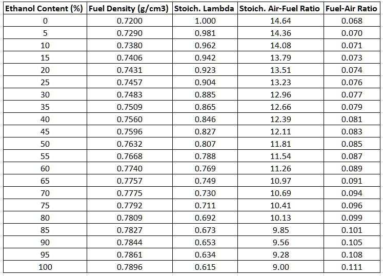
Fuel Settings Matrix for ethanol content (reference only)
Introduction to HDFX
We often receive questions about the engine control strategies being utilized in the Ford Ecoboost ECU. While most of the answers to these questions fall under information we have available in our Tuning Guide, there are some more advanced topics that have recently become necessary to explain and explore. In this document we will introduce you to a more technical understanding on how these engine controls operate using Ford's HDFX strategy and the way Volumetric Efficiency is determined.
What is HDFX?
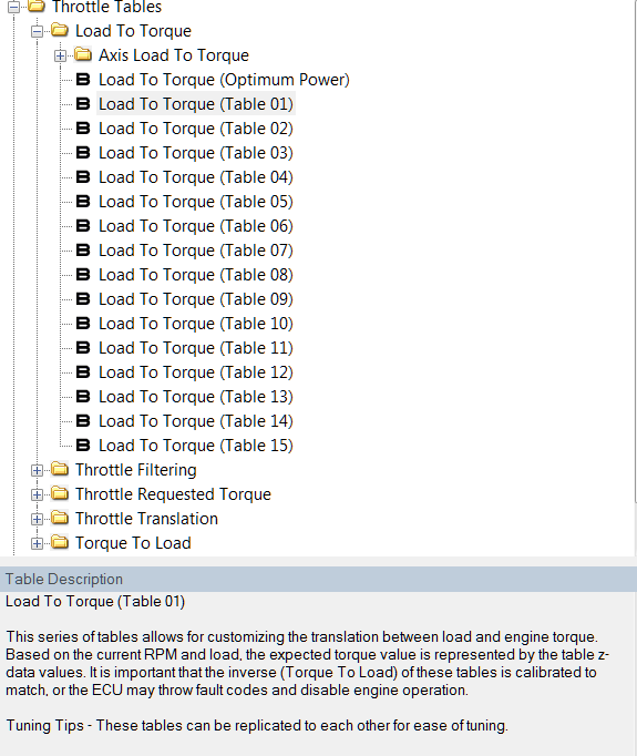
HDFX stands for "High Degree of Freedom Executive." It is a strategy that Ford has implemented to allow dynamic blending between a series of calibrated tables. You've likely seen these table sets (Table 01 – Table 15) in our software and wondered about their relationship to one another.
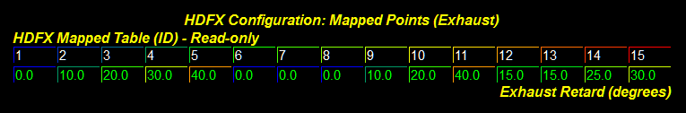
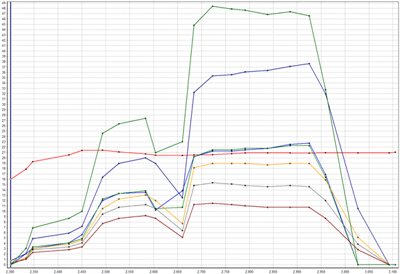
These tables are individually calibrated from Ford for the respective VCT (Variable Cam Timing) angle pair as defined by the pairing reference shown above. From left to right, these mapped pairs represent Table 01 – Table 15. These pairs will vary by vehicle. As camshaft angles change during engine operation the ECU creates a weighting factor for each of these tables. These weighting factors represent the percentage of how much of a table will be blended into the final calculation and can be viewed with the HDFX Table Weight 01-15, and OP monitors.
For example, if the engine was currently running -30°i, 11°e; we would likely be at a 50/50 blend of Table 08 and 09. Knowing which tables are being used at any given time is crucial to the calibration process!
There is one exception to this strategy which occurs when the "Optimum Power" (OP) mode is active.
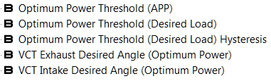
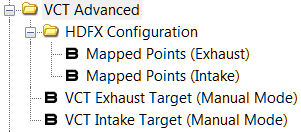
Most of the vehicles which we support have by default disabled weighting for the OP tables. We highly recommend taking the time to adjust and verify the tables associated with each VCT mapped pair for best results. This can be done by using the VCT Manual Mode toggle, and setting the VCT Exhaust/Intake Target (Manual Mode) values to match a specific table pairing.
Volumetric Efficiency
What is Volumetric Efficiency (VE)?
In simple terms, VE is the measured ability of an engine to move an air charge in and out of its cylinders. VE is often measured as a ratio or percentage. For the intent of this document and our software we will reference percentages. Normally aspirated motors will often struggle to achieve 100% VE, while an efficient forced induction engine will often exceed 100% for most of its boosted power-band.
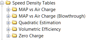
How does Ford calculate VE?
Ford has devised a model to calculate, estimate, monitor, and react to VE changes through various iterations of the slope-intercept linear equation (y=mx+b). The slope (m) is represented by values in the MAP vs Air Charge folder. The intercept (b) is represented by values in the Zero Charge folder. The equation uses Manifold Air Pressure (MAP) for ( x ) and results with ( y ) as Aircharge mass.
This value only gets us halfway there. We still need to know the inlet density to calculate VE. This is where the Ford mathematicians went to town through a series of advanced algorithms. They came up with a method to calculate dry air density, and single cylinder displacement for any engine size. By providing the displacement of the engine in liters, the number of cylinders, and the current MAP, the ECU can calculate inlet density.
Unfortunately, all of this math is done in background processes in the ECU, manipulated for specific uses, and is never stored for monitoring at the moment we need it. That wasn't going to stop us from extracting this important calibration data. We have injected custom code to generate data monitors which allow real-time viewing of the modeled VE, and VE for the currently measured aircharge.
Why is this data important?
This model is responsible for measuring inputs from the MAP/TIP/Baro sensors and translating them into aircharge, load, airflow, torque, and other governable unit types. The accuracy of this translation is extremely important to ensure all of the dependent models are fed with relevant data. These dependent models include but are not limited to Fuel, Timing, Boost, Wastegate, Torque, and Airflow. The ECU can correct for discrepancies against the model up to an extent. However, it is best practice to re-calibrate the core VE model when components are replaced that can change the actual VE of the motor. This includes components such as an intake, exhaust, turbocharger, camshafts, headwork, and pistons.
How do I ensure my VE model is accurate?
I'm glad you asked. As mentioned earlier, we've added some new monitors to make this portion of calibration less painful. We've also put together a handy VE spreadsheet to use as a tuning aid. Check the resources section at the end of this document for a link to access this spreadsheet. Let's go over one of the strategies that can be used to quickly dial in your VE curves.
Calibrating VE (OEM Style)
For information on the COBB Speed Density system visit Ford EcoBoost Speed Density Guide
Gathering Data
We first need a good baseline of data to determine the scope of potential changes. This is done by logging a few WOT pulls with specific monitors over the entire operating range (~1500-6800rpm).
You'll want the following monitors at minimum: (C) Estimated VE Model Corrected, (C) Estimated VE Actual Corrected, Actual AFR, Boost Pressure, Commanded EQ Ratio, Engine Speed, Load Actual, Long Term Fuel Trim,Short Term Fuel Trim, VCT Exhaust Angle Actual, VCT Intake Angle Actual
The resultant data will allow you to visualize the VE curve of the engine and determine if there are areas in need of improvement. This is done by analyzing the STFT/LTFT corrections against the delta between Modeled VE and Actual VE.
Making Changes to the VE Curve
If the STFT+LTFT value is positive it means the ECU is not commanding enough fuel and therefore needs additional VE. For this example, we will assume that the total correction amount at 2500rpm is +15% and it tapers to 0% by 5000rpm. Let's also assume that we know based on the HDFX reference table that between 2500-5000rpm we're utilizing 100% of Table 06. This means we'll want to make changes to the Slope of MAP vs Air Charge (Table 06) to resolve the inaccuracy.
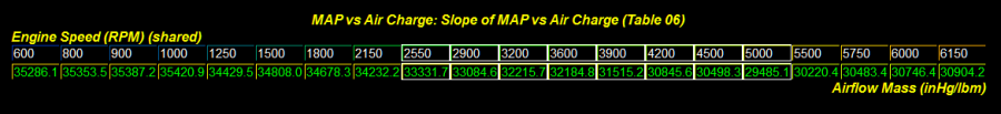
To increase VE subtract values, to decrease VE add values. We would multiply the value at ~2500rpm by 0.85 to increase VE by 15%, and continually decrease that trend towards 5000rpm. Use the table graph as a visual means to keep the overall table as smooth as possible. If other tables were actively weighted, make similar percentage changes to the same areas before performing your next reflash.
Advanced VE Tuning
There are more advanced methods to calibrate VE once the basic concepts above have been exercised and familiarity on the process grows. We introduced you to HDFX earlier and now it's time to apply those resources. We will now demonstrate how to fine tune a single HDFX VE table. Once again you'll need a few WOT pulls with specific monitors over the entire operating range (~1500-6800rpm).
To determine which HDFX VE table is being used monitor the following: HDFX Weight Table (ALL), (C) Estimated VE Model, (C) Estimated VE Actual Corrected, Actual AFR, Boost Pressure, Comm. EQ Ratio, Engine Speed, Long Term Fuel Trim, Short Term Fuel Trim, VCT Exhaust Angle Actual, VCT Intake Angle Actual, VE Correction Ratio
The resultant data will allow pinpointing of a particular table for fine tuning. In this example we'll begin with Table 14. From the reference table used earlier we can determine the VCT pair is -18°i, 22°e. Now it's time to lock the cams and dial in this table.

Start by enabling VCT Manual Mode in the toggles (CTRL+A). Follow this by changing the VCT Exhaust/Intake (Manual Mode) values to the Table 14 references (-18°i, 22°e).
Now that the cams are locked, a new series of data can be collected to continue.
You'll want the following monitors at minimum: (C) Estimated VE Model, (C) Estimated VE Actual Corrected, Actual AFR, Boost Pressure, Commanded EQ Ratio, Engine Speed, Load Actual, Long Term Fuel Trim, Short Term Fuel Trim, VE Correction Ratio
The goal here is to adjust one table at a time to ensure the VE model is accurate. This method can also be utilized for the remainder of VCT pairs to ensure accuracy under all camshaft angles. It's also going to be a great time to open up that COBB Ford VE TUning Aid which covers the stock VE behavior (not COBB Speed Density) to visualize how your changes will look before applying them. The spreadsheet will allow you to visualize the result of higher pressures without having to stress the engine.
Using the COBB VE Tuning Aid
There are several input fields available to allow the ease of copying and pasting values from Accesstuner software. See the legend for the color representation of these fields. The default values are configured for a 2.0L Ecoboost Focus ST but can be swapped easily for any engine. We have included values for a few popular vehicles. The OEM slope-intercept values have been supplied for these vehicles on the HDFX References tab. For this example we'll stick with the Focus ST defaults.

First we'll choose a VCT pair for review and populate the slope and offset values. If starting from scratch, use the HDFX References tab and "paste values" to retain formatting. If you have already modified values in your calibration, simply copy and paste them from Accesstuner. The VE data will auto-populate below, along several other conversions further down.
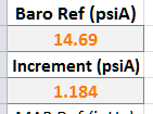
Next, input Barometric Pressure. This can be obtained by using the Accessport. The final step is to select a pressure increment for the graph. This will allow fine or coarse granularity for the charts below. We've placed a conversion reference for Boost Pressure and MAP on the primary axis to aid in the process.

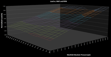
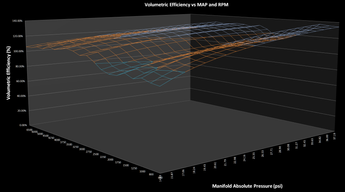
Now that the basic inputs have been entered the VE model can be viewed in all of its 3D glory! Additionally you'll find charts that represent Aircharge, Load, and Pressure throughout the spreadsheet. Make changes as needed to the slope and intercept values to obtain a desired VE curve. Once changes are complete, simply copy and paste these values back into Accesstuner and gather new data.

Resources
- COBB VE Tuning Aid - COBB_Ford_VE_Tuning_Aid.xlsx
- Engine & Transmission Monitor List for Ford Vehicles
Reference Material
U.S. Patent Number 5357932A – Fuel control method and system for engine with variable cam timing
U.S. Patent Number 6115664A – Method of estimating engine charge
U.S. Patent Number 6850831B2 – Method and system for estimating cylinder charge for internal combustion engines having variable valve timing
U.S. Patent Number 6851304B2 – Air estimation approach for internal combustion engine control
U.S. Patent Number 7380447B2 – Method and system for transient airflow compensation in an internal combustion engine
The Big Orange Heavy Thing – Injector Dynamics
Copyright 2025 © COBB Tuning Products LLC. All Rights Reserved. | www.cobbtuning.com