Tech Bulletin - Configuring a Base Map for a Big-Turbo Ford EcoBoost


Applicable Vehicles:
The following vehicles designed for and sold in all regions unless otherwise noted are supported:
- 2014-2019 Fiesta ST (USDM Only)
- 2013-2018 Focus ST
- 2016-2018 Focus RS
- 2015-2017 Mustang EcoBoost
Configuring a Base Map:
Step 1: Select a COBB OTS map
We recommend that you start with a COBB OTS map that best fits the modifications for the car. The vehicle used for our example tune is a 2016 Focus RS. This vehicle is equipped with a COBB intake, intercooler, turbo-back exhaust, and a Precision turbocharger running on 93 OCT/98 RON fuel. We chose to start with the Stage 2+ 93 OCT or 98 RON v301 map.
Step 2: Enable and configure CCF Wastegate controls
To bypass the OEM wastegate controls, we will need to flip some enable switches for the CCF control system. We’ll start with ‘Master Switch (CCF WG Features)’:
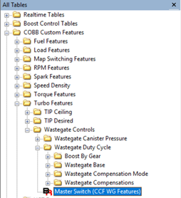
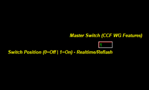
This setting will activate the use of several CCF Features applicable to wastegate control and pressure targets/limits. If ANY of these features are desired, this switch must be enabled.
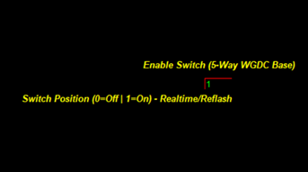
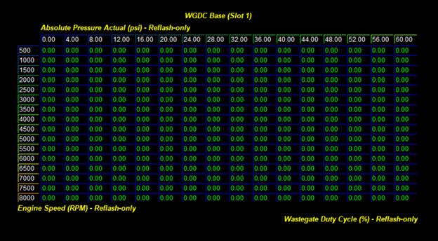
Next, we’ll configure ‘Enable Switch (5-Way WGDC Base)’. This switch enables the use of the CCF WGDC Base tables – note that up to 5 different WGDC base tables can be configured in different map slots, and can be tuned in real-time.
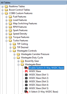
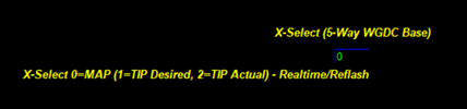
The WGDC Base tables have axes of RPM (Y) and Pressure (X), and will output a feed-forward WGDC. The pressure source is configurable with the table ‘X-Select (5-Way WGDC Base)’. For now, leave the tables zeroed-out.
The default setting for ‘X-Select (5-Way WGDC Base)’ is 0, which will use MAP as the x-axis in the WGDC Base table; 1 will use TIP Desired, 2 will use TIP Actual.
With the feed-forward WGDC Base tables enabled and configured, we’ll next look at what sort of compensations we would like to enable for the tune. The choices that are available to you depends on the vehicle you’re tuning. Within the Fords that we support, the OEM boost control strategies can be categorized as either “Canister Pressure Strategy” or “Airflow Strategy”.
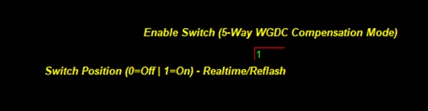
To enable use of CCF WGDC Compensation, first find the table ‘Enable Switch (5-Way WGDC Compensation Mode’. Configure this table to ‘1’ to enable the feature set.
Canister Pressure Strategy Vehicles:
These vehicles have the option of running one of four compensation configurations. Two of these compensation modes utilize the factory WGDC Base table, and two use the COBB CCF WGDC Base table. Here are a breakdown of the individual mode differences:
- Mode 1 – USES STOCK WGDC BASE TABLE; functions like stock, but with added Barometric Pressure compensation and an X-Select (Temperature) compensation.
- Mode 2 – USES STOCK WGDC BASE TABLE; incorporates Mode 1 functionality + additional compensations for Charge Air Temperature, TIP Boost Error, and Load Error.
- Mode 3 – USES COBB CCF WGDC BASE TABLE; uses identical compensations as Mode 1
- Mode 4 – USES COBB CCF WGDC BASE TABLE; uses identical compensations as Mode 2
Airflow Strategy Vehicles:
These vehicles have the option of running one of six compensation configurations. Three of these compensation modes utilize the factory WGDC Base table, and three use the COBB CCF WGDC Base table. Here are a breakdown of the individual mode differences:
- Mode 1 – USES STOCK WGDC BASE TABLE; functions like stock, but with new clipping points available for the P-term and PI-error. Also includes Barometric Pressure and an X-Select (Temperature) compensation. These clipping points do not exist in the OEM implementation of boost control and allow for limiting of the range for PID response on the P-term and the response of the I-term.
- Mode 2 – USES STOCK WGDC BASE TABLE; incorporates Mode 1 functionality + additional compensations for Charge Air Temperature, TIP Boost Error, and Load Error.
- Mode 3 – USES STOCK WGDC BASE TABLE; disables the OEM P-term and I-term. This method only uses the OEM WGDC Base table + COBB Barometric Pressure, Temperature (AAT/IAT/ECT), Charge Air Temperature, TIP Boost Error, and Load Error compensations. This is meant for those that do not with to use, or have not had positive results with the OEM P/I controls.
- Mode 4 – USES COBB CCF WGDC BASE TABLE; uses identical compensations as Mode 1
- Mode 5 – USES COBB CCF WGDC BASE TABLE; uses identical compensations as Mode 2
- Mode 6 – USES COBB CCF WGDC BASE TABLE; uses identical compensations as Mode 3
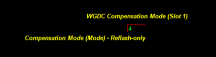
Our example vehicle – a Focus RS – is a canister pressure vehicle, so we’ll choose between modes 1-4. Since we also want to use the COBB CCF WGDC Base table for tuning, we’ll choose between modes 3 and 4. For this vehicle, we chose Mode 4 – note that you do not need to tune all active compensations, as they will default to a multiplier of 1 and will not change WGDC.
In summary, we have configured CCF wastegate control to:
- Enable ‘Master Switch (CCF WG Features)’
- Enable ‘Enable Switch (5-Way WGDC Base)’
- Left all ‘WGDC Base (Slot 1-5)’ tables at 0% WGDC
- Enabled ‘Enable Switch (5-Way WGDC Compensation Mode)’
- Selected Mode 4 for ‘WGDC Compensation Mode Slot 1-5)’
Step 3: Enable and configure boost ceiling safety
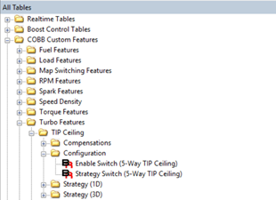
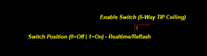
Here we will configure our absolute boost limit safety. This will dictate the maximum amount of throttle inlet pressure prior to throttle closure. Within the TIP Ceiling folder, you will find a table called ‘Enable Switch (5-Way TIP Ceiling)’. Configuring this table to ‘1’ will allow use of COBB CCF TIP Ceiling as your upper boost limit.
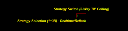
Just below this table is ‘Strategy Switch (5-Way TIP Ceiling)’. This table determines whether the 1D TIP Ceiling tables or the 3D TIP Ceiling tables are used as the boost limit. We recommend using the 3D tables for superior control and resolution through the engine’s range of operation. Set this table value to ‘1’ to select 3D control.
Since we are creating a wastegate spring pressure base-map, you can set this absolute pressure limit to a few PSI higher than what you expect the turbo to make on 0% WGDC. As you modify your tune to increase boost, don’t forget to increment this table upwards to stay clear of your target boost pressure (but not too far off!).
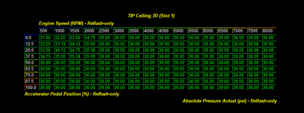
We bench tested the cracking pressure of the wastegate spring of the turbo we had installed on the Focus RS, and found it to be around 16 PSI. We know that this engine can handle quite a bit more boost than just 16 PSI, so we configured our absolute TIP Ceiling to be 36 PSI to give us a safe window to play around in for the first few map iterations.
In summary, we have configured CCF TIP Ceiling controls to:
- Enabled ‘Enable Switch (5-Way TIP Ceiling)’
- Selected 3D control of the ‘Strategy Switch (5-Way TIP Ceiling)’
- Configured a safe absolute TIP Ceiling in ‘TIP Ceiling 3D (Slot 1-5)’.
Step 4: Enable and configure TIP Desired targets
The OEM boost control system will use throttle inlet pressure (TIP) targets derived from calibrated requested torque and torque-to-load translations. This can provide great drivability at lower throttle inputs, but can be a challenging system to efficiently tune at higher boost pressures on a big-turbo vehicle.
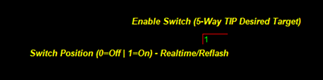
As a part of the custom feature set, we have implemented both a throttle position breakpoint/control switch point and a custom TIP Desired target to bypass OEM logic. We’ll start by enabling the system with the table ‘Enable Switch (5-Way TIP Desired Target)’. Configuring the table value to 1 will enable the CCF TIP Desired system.
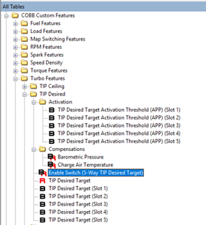
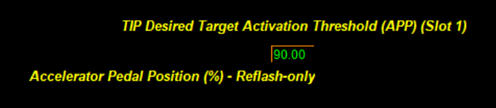
Next, we’ll configure the activation threshold at which the CCF TIP Desired values will be used, bypassing the OEM calculations. Below this APP threshold, OEM calculations will be used. You will want to select a throttle position for the activation threshold that allows for a smooth transition between OEM and CCF calculated TIP Desired. For the purpose of the base map and tuning WOT behavior, the number initially used isn’t particularly important, and can be fine-tuned later in the process.
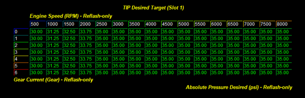
With the system enabled and an activation threshold set, we can begin working with the 3D TIP Desired table. Notice that the Y-axis is populated with gear values, and the X-axis with RPM.
In summary, we have configured the CF TIP Desired controls to:
- Enable ‘Enable Switch (5-Way TIP Desired Target)’
- Configured activation point in ‘TIP Desired Target Activation Threshold (APP) (Slot 1-5)’
- Configured a sensible TIP Desired in ‘TIP Desired Target (Slot 1-5)’
Step 7: Iterate on WGDC commands and pressure targets
As you iterate on this base map to increase boost pressure, be sure to match increases to WGDC with increases to TIP Ceiling and TIP Desired Target. All three tables are editable in real-time - be sure to copy working data into map slot tables and SAVE FREQUENTLY!
Step 8: Evaluate options for boost control compensations
Before sending the customer home with their newly tuned big-turbo EcoBoost, review some of the available CCF boost control compensations.
TIP Ceiling:
- Gear-Based
TIP Desired:
- Barometric Pressure
- Charge Air Temperature
WGDC:
- Boost by Gear
- Barometric Pressure
- Charge Air Temperature
- Load Error
- TIP Boost Error
- Temperature (Ambient, Intake, or Coolant)
Links:
Copyright 2023 © COBB Tuning Products LLC. All Rights Reserved. | www.cobbtuning.com