COBB Custom ECU Features
- Will Trang
- Brandyn Mowat

![]()
All COBB Supported EcoBoost Applications
* Disclaimer - Improper changes to your vehicle control strategy may result in engine failure ***
COBB Custom Features (CCF)
Since our initial entry into the Ford platform in December of 2012 we have delivered industry leading support, calibrations, hardware, and software for several EcoBoost powered vehicles! We've listened to the community, monitored the development of the aftermarket, and added support as products developed. We strive to be industry leaders and educate the community to make empowered decisions. The culmination of this passion to deliver the ultimate tuning solution has lead us to create amazing new features inspired by you; our customers. COBB is proud to bring exciting new features and functionality for your vehicle!
What is it?
A fully customizable feature framework that is powered by community innovation and feedback. We have created a base set of features that enable 5-way Map Switching, Traction Control, additional wastegate duty cycle compensations, per-gear TIP targets, hot swappable launch control, Flat-Foot-Shifting (FFS), and many other useful features. Available only from COBB!
Why would you do such a thing?
Together we have discovered many nuances that can prevent the tuning process from being simple and straightforward. By adding our custom code to the ECU we can unlock the true potential of the aftermarket and deliver solutions that continue to push the platform further.
What else is possible?
With this framework in place, we have the ability to add new features or functionality to your ECU. Have an idea or a suggestion that could make more power or enhance the driving experience? Chances are we can make it happen! Submit your ideas and suggestions to support@cobbtuning.com and we'll do our best to incorporate them in future updates.
General Notes About Configuring Features
Generally, each feature or table can be individually enabled as desired. If a feature is disabled, OEM logic will be used. Features may have multiple strategies and can have standard or advanced modes. By default only one of five map slots are enabled and all slot based features are disabled. If more than 1 slot is desired, modify the "Active Map Slots" table accordingly. This table can be adjusted in realtime. As long as the value in the Active Map Slots is great than 1 and up to 5, this value can be live adjusted upwards/downwards between 1-5. As an added bonus, the vehicle tachometer will indicate the current map slot in 1000 RPM increments when this is modified.
Configuration settings must be changed to take advantage of most custom features.

Feature: 5-Way User Selectable Map Switching
Description
Map switching allows for instant changes to several tables inside the vehicles calibration without having to re-flash the ECU! Each "map slot" is grouped into a folder found inside the Map Switching Features group. When a map slot is selected by the driver, the ECU will use the corresponding values as defined in each folder.
Dependencies / Requirements
Compatible calibrations and firmware must be used to take advantage of this feature. Only features that have been configured as enabled will be used. Conditions must also be met in order to use the feature.
Using This Feature
Map switching can be performed while the vehicle is moving. Changing map slots is done by using the cruise control buttons on the steering wheel, on the Accessport itself, or within Accesstuner software.
To adjust the map slot using the cruise control buttons, first, ensure the cruise control system is OFF. Next press the Map Switching Menu Button on the steering wheel to activate the user interface (see the CC button assignments document below).
An indicator of the currently active map slot will show on the tachometer in increments of 1000. To change map slots use the Slot Up and Slot Down buttons until the desired map slot is selected. The tachometer will resume normal operation after ~2.5 seconds and the map switching menu will automatically exit after ~10 seconds of inactivity. If the vehicle begins to move or the cruise control OFF or ON/OFF button is pressed, this map switching user interface will be disabled.
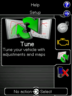
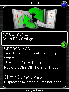
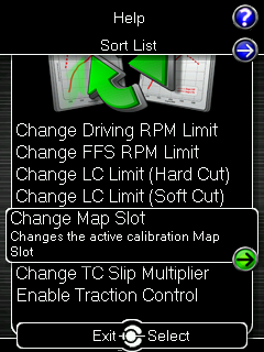
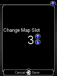
To adjust the map slot using the Accessport, navigate to the main menu of the AP, select TUNE — ADJUSTMENTS — CHANGE MAP SLOT — Select the desired map slot.
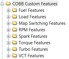
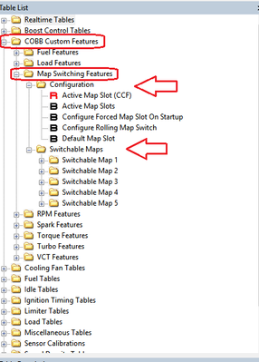
To adjust the map slot using the Accesstuner software, open the COBB Custom Features folder, select Map Switching Features Folder and make the desired adjustments.
What To Monitor
To see the currently active map slot, use the (CCF) Map Slot monitor.
Warnings
The end-user accepts all risks and responsibilities when using this feature.
Here's a brief video showcasing COBB Map Switching!
Custom Feature Cruise Control Button Assignments

Feature: Launch Control (MT Only, Hotswap LC unavailable on the Focus RS)
Description
Launch Control (LC) is a system to help the driver and vehicle perform more consistently during take off. The COBB LC system has been designed to offer greater flexibility of existing OEM-like control, along with the ability to add future functionality. Several new requirements and conditions have been added to allow a single calibration to be used on the street, strip, track, and dyno.
Our solution provides two styles of engine speed control. The default is Hard Cut for those who prefer to build boost while preparing to launch. The alternate is Soft Cut for those who prefer to launch the vehicle without building (as much) boost. The latter method avoids placing undue stress on the engine by utilizing the OEM Target N control PID systems.
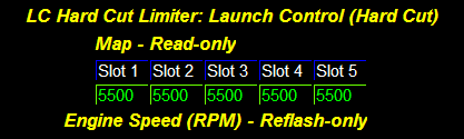
This feature is included in our 5-way map switching table assortment. There are 3 tables in total that will need to be modified per map slot if the Enable Switch (5-Way LC Hard/Soft Cut Rev Limit) settings are enabled. If they are not enabled for 5-Way operation the value in Map Slot 1 of the switchable table values will be used for operation.
Additionally, we have added the Launch Control (Hard Cut) Offset table to allow both launch limiter methods to be set at the same RPM without interfering with one another. This offset value is added to the Hard Cut limiter in the event that it is lower than the Soft Cut limiter. This is due to the logic in the ECU that will choose the lower of all active rev limiters. For example, if you wanted a hard cut launch set to 3500rpm, and a soft cut launch set at 4000rpm, the offset would need to be set to at least 600rpm so that the soft cut will be lower during its activation. We recommend making sure the delta between the two limiters is at least +500rpm for best results.
Dependencies / Requirements
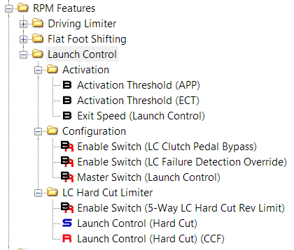
See the RPM Features sub-folder inside of the COBB Custom Features main folder for configuration settings.
- Launch Control is enabled by activating Master Switch (Launch Control). If this switch is not enabled, the vehicle will function the same as OEM.
- Normally, the Clutch Pedal is required to activate the LC system. This ensures the vehicle disengages a lower RPM limit during acceleration as soon as the clutch is released. However, for some vehicles it can be beneficial to "ride" the launch limiter while the tires gain traction and disengage the RPM limit via the Exit Speed (Launch Control). To disable the clutch pedal requirement activate the Enable Switch (LC Clutch Pedal Bypass).
- Set the desired exit speed using the Exit Speed (Launch Control) table.
- The last of the requirements is the Activation Threshold (APP). This is the minimum required accelerator pedal position needed to activate the LC system when all other requirements are met.
Using This Feature
There are multiple conditions that must be met in order for the LC feature to be used.
- Burnout mode must not be active (see more about the Burnout Mode feature below).
- Vehicle Speed from the un-driven wheels must be under the Exit Speed (Launch Control).
- Accelerator Pedal Position must be over the Activation Threshold (APP).
- The vehicle must be in neutral, 1st or 2nd gear.
- The Clutch Pedal Position must be at least partially engaged if the Enable Switch (LC Clutch Pedal Bypass) is not activated.
- To utilize the Hard Cut limiter, only the previous conditions are required.
- To utilize the Soft Cut limiter, the Hotswap LC button must be held down (if available).
Once the vehicle is launched and conditions are no longer met the ECU will resume normal operation of the engine speed limiters.
What To Monitor
(CCF) LC Status – Status of the launch control feature. 0=Inactive, 1=Active.
(CCF) Driving RPM Limit – The currently active driving rev limiter (primary limiter).
(CCF) LC HC RPM Limit – The current RPM target for use with the Launch Control feature.
(CCF) LC SC RPM Limit – The current RPM target for use with the Hotswap LC feature.
Warnings
WARNING: Launch Control, Flat-Foot-Shift (LC/FFS), and Burnout Mode are abusive to the engine, clutch, transmission, axles, and differential. The user accepts all risks and responsibilities when using these features.
Feature: Launch Control (Focus RS Only)
Addendum coming soon!
Feature: Burnout Mode (unavailable on the Focus RS)
Description
This feature was developed initially as a protection against over-revving during a burnout, but also to remove complexity from the tire warmup process while preparing for a blast down the strip. It's also great for "demonstrations" to those who don't believe that your EcoBoost can light 'em up! Burnout mode offers two styles of engine speed control, Hard Cut and Soft Cut. While similar to Launch Control operation, the Throttle Cut used in Burnout mode takes advantage of additional OEM torque control systems to provide enough power for burnouts when a Fuel Cut is not necessary. This is a configurable setting using the Strategy Switch (Burnout Mode) table.
Dependencies / Requirements
There are multiple conditions that must be met in order for the burnout feature to be used.
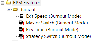
- The Master Switch (Burnout Mode) must be enabled for this feature to be used.
- Set the RPM limit for Burnout Mode with the Rev Limit (Burnout Mode) table.
- Set the desired exit speed using the Exit Speed (Burnout Mode) table.
Using This Feature
- Launch Control (if available) must not be active.
- The Burnout button must be held down.
- Vehicle Speed from the un-driven wheels must be under the Exit Speed (Burnout Mode).
- The vehicle must be in neutral, 1st or 2nd gear (shared logic with Launch Control).
If the Burnout button is released or conditions are no longer met the ECU will resume normal operation of the engine speed limiters.
To perform a burnout using the burnout button, follow these simple steps:
Automatic Transmission Vehicles
- If equipped with a drive mode switch, set the drive mode to "Track".
- Hold the traction control button down for ~6sec to disable Advancetrac.
- Set the shifter into the "S" selector and tap the "-" paddle to engage manual shifting mode.
- Hold your left foot on the brake.
- Hold the Burnout button down.
- Push the accelerator pedal to the floor.
- Modulate the burnout with your left foot. We also recommend shifting into 2nd gear.
- Once the tires are warm, release the brake, accelerator pedal, and the burnout button!
Manual Transmission Vehicles
- If equipped with a drive mode switch, set the drive mode to "Track".
- Hold the traction control button down for ~6sec to disable Advancetrac.
- Press and hold the clutch in and put the car into 1st gear.
- Hold the Burnout button down.
- Push the accelerator pedal to the floor and release the clutch.
- Immediately after releasing the clutch, place your left foot on the brake pedal.
- Modulate the burnout with your left foot.
- Once the tires are warm, release the brake, accelerator pedal, and the burnout button!
What To Monitor
(CCF) Burnout Status – Status of the burnout feature. 0=Inactive, 1=Active.
Warnings
WARNING: Launch Control, Flat-Foot-Shift (LC/FFS), and Burnout Mode are abusive to the engine, clutch, transmission, axles, and differential. The user accepts all risks and responsibilities when using these features.
See this feature in action on our COBB Mustang EcoBoost (AT)!
Feature: Flat-Foot-Shifting (FFS) (MT Only)
Description
FFS was designed to allow your foot to remain on the accelerator pedal while shifting quickly. The system temporarily lowers the rev limiter so the engine is not over-revved when the clutch is pressed. This allows for more aggressive, quick, and safe shifts.
Dependencies / Requirements
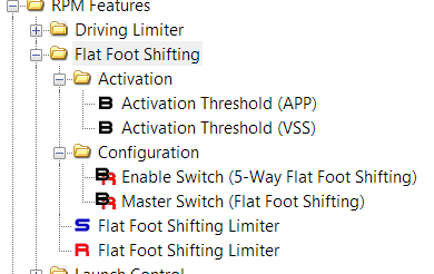
- The Master Switch (Flat Foot Shifting) must be enabled for FFS to be used.
- Accelerator Pedal Position must be over the Activation Threshold (VSS) table value.
- Vehicle Speed must be over the Activation Threshold (VSS) table value.
- The clutch pedal must be at least partially engaged.
Using This Feature
- Simply accelerate to an RPM greater than the Flat Foot Shifting Limiter while maintaining an Accelerator Pedal Position higher than the Activation Threshold (APP) and push the clutch in. Engine Speed will drop and hold at the RPM specified in the table.
What To Monitor
(CCF) FFS RPM Limit – The current RPM target for use with the Flat-Foot-Shift feature.
(CCF) FFS Status – The status indicator for the Rev Limit FFS feature (1=Active).
Warnings
WARNING: Launch Control, Flat-Foot-Shift (LC/FFS), and Burnout Mode are abusive to the engine, clutch, transmission, axles, and differential. The user accepts all risks and responsibilities when using these features.
See this feature in action!
Feature: Wastegate Duty Cycle
Description
This feature has been designed to aid those who are using boost control as a priority in their tuning strategy. There were several caveats found in the OEM wastegate controls that could result in inconsistent boost control under varying conditions. There were also several complex algorithms involved in the turbo model that prevented easy calibration with upgraded turbochargers. With the following system in place, achieving consistent and reliable boost control is realized.
Dependencies / Requirements
- The Master Switch (CCF WG Features) must be enabled for any of features in the Wastegate Duty Cycle sub-folders.
- Note: There are additional compensations depending on application, such as Battery Voltage, Soak Temp, etc… that are applied prior to the final calculation of WGDC. These compensations are subtracted from (CCF) WGDC Final. While minimal, keep these additional compensations in mind when calibrating wastegate control.
What To Monitor
- (CCF) WGDC Base shows the value as looked up from the COBB WGDC Base table.
- (CCF) WGDC Pre-Final shows the value after Barometric Pressure and Temperature (AAT/IAT/ECT) compensations have been applied.
- (CCF) WGDC Final shows the value after all compensations, including Boost By Gear.
Warnings
Improper settings for boost control can lead to over-boosting conditions. If not properly limited, excessive boost pressure can cause engine damage.
Using This Feature
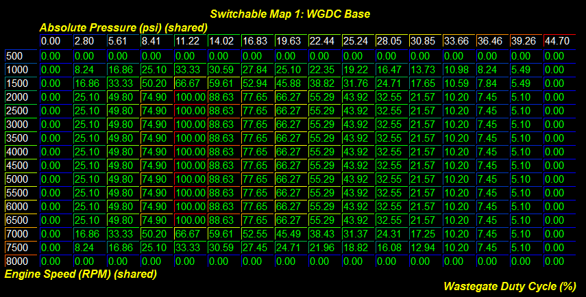
This new table utilizes a configurable pressure along the X-Axis and Engine Speed (RPM) along the Y-Axis. You can choose between Manifold Absolute Pressure, TIP Desired, or TIP Actual to accommodate tuning preference by modifying the X-Select (5-Way WGDC Base) table accordingly.
Using pressure allows the table to act as a pseudo self-contained PID system by creating a slope in between pressure points for wastegate duty cycle regulation. With proper values, boost control can be extremely tight with minimal oscillation. Combined with our WGDC Compensations and other 5-way features, the use of these tables offers a simple and efficient means to create multiple boost levels for varying conditions and fuels.
To enable the COBB WGDC Base tables, simply set the Master Switch (CCF WG Features) and Enable Switch (5-Way WGDC Base) to 1. By doing this, you will also automatically enable* the 5-way WGDC Compensation Modes. Be sure to check over the settings in each of your map slots to ensure proper base settings and compensations are being used.
- Note: A full blown PID controller is in the works, stay tuned for updates!
*If the 5-way WGDC Base feature is enabled, but the 5-Way WGDC Base strategy is not, the code will automatically enable 5-way WGDC Compensation Modes for you. This is done as a protection as Modes 3 and 4 are only available when the 5-way WGDC Base strategy is active.
Feature: Wastegate Compensations / Modes
Description
This feature has been designed to aid those who are using boost control as a priority in their tuning strategy. There were several caveats found in the OEM wastegate controls as well as the initial implementation of the COBB WGDC Base that could result in inconsistent boost control under varying atmospheric conditions. With the following system in place, achieving consistent and reliable boost control can be realized. Please use the diagram as a logic overview and reference.
Dependencies / Requirements
- The Master Switch (CCF WG Features) must be enabled for any of features in the Wastegate Duty Cycle sub-folders.
Using This Feature
See the outline of WGDC Compensation modes below.
What To Monitor
See the outline of WGDC Compensation modes below.
Warnings
Improper settings for boost control can lead to over-boosting conditions. If not properly limited, excessive boost pressure can cause engine damage.
(Canister Pressure Strategies)
(Canister Pressure Strategies)
WGDC Compensation Modes 1 & 2 (Non 5-way and 5-way)
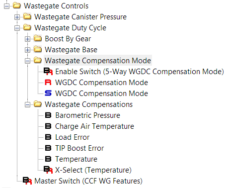
There are 2 compensation modes available when the Enable Switch (5-Way WGDC Compensation Mode) is set to 0. These 2 modes were designed for stock turbo configurations which utilize the OEM WGDC Base table. For those wishing to use the COBB WGDC Base, please see the description for modes 3-4.
- Mode 1 – Functions like stock, but with added Barometric Pressure and a X-Select (Temperature) (AAT/IAT/ECT) compensation.
- Mode 2 – Incorporates Mode 1 + additional compensations for Charge Air Temperature, TIP Boost Error, and Load Error. This allows for an immense amount of control over the wastegate.
- By default all of the switchable map values for WGDC Compensation Mode are set to 1. Refer to the (CCF) WGDC Comp Mode monitor to view the currently active mode.
(Canister Pressure Strategies)
WGDC Compensation Modes 3 & 4 (Only available in 5-way configuration)
There are 4 compensation modes available when the Enable Switch (5-Way WGDC Compensation Mode) is set to 1. The first 2 modes were mentioned earlier and still use the OEM WGDC Base table. The remaining 2 modes will use the COBB 5-way WGDC Base table. This allows a massive amount of customization for each map slot!
- Mode 3 – Identical to Mode 1, but uses the COBB 5-way WGDC Base table.
- Mode 4 – Identical to Mode 2, but uses the COBB 5-way WGDC Base table.
NOTE: If the 5-way WGDC Compensation Mode feature is enabled, but the 5-Way WGDC Base strategy is not, the code will automatically enable 5-way WGDC Base for you. This is done as a protection as Modes 3 and 4 are only available when the 5-way WGDC Base strategy is active.
How These Compensations Are Applied
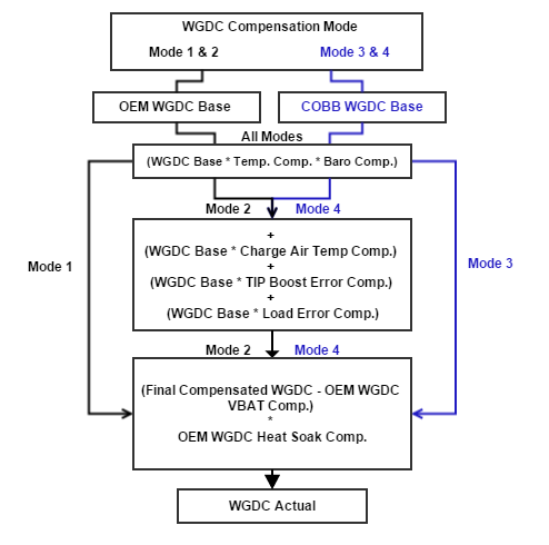
The compensations have a specific order and operation. This is done to ensure that atmospheric and temperature conditions are accounted for at all times. See below for the math that is working behind the scenes! Note that Barometric Pressure and Temperature compensations are always active regardless of the compensation mode.
- (WGDC Base * Baro. Comp) * Temperature Comp. =
- WGDC Base * CAT Comp. = CAT Comp %
- WGDC Base * TIP Boost Error Comp. = TIP Boost Error Comp %
- WGDC Base * Load Error Comp. = Load Error Comp % (Note: Load Desired (Tq Ctrl) – Load Actual = Load Error)
- ((CCF) WGDC Final - VBAT Comp.) * WGDC Heat Soak Comp. = WGDC Actual %
- WGDC Actual % can then be modified by Boost By Gear before being clipped between 0-100%.
All of these calculations are done continuously and are combined into the (CCF) WGDC Final monitor according to the active (CCF) WGDC Comp Mode. The (CCF) WGDC Final value will then subtract the OEM WGDC Battery Compensation, multiply that value by the WGDC Heat Soak Compensation, and finally clipped the result between 0-100% to become WGDC Actual.
(Airflow Strategies)
(Airflow Strategies)
WGDC Compensation Modes 1-3 (Non 5-way and 5-way)
There are 3 compensation modes available when the Enable Switch (5-Way WGDC Compensation Mode) is set to 0. These 3 modes were designed for stock turbo configurations which utilize the OEM WGDC Base table. For those wishing to use the COBB WGDC Base, please see the description for modes 4-6.
- Mode 1 – Functions like stock, but with new clipping points available for the P-Term and the PI-Error. Also includes Barometric Pressure and a X-Select (Temperature) (AAT/IAT/ECT) compensation. These clipping points do not exist in the OEM implementation and allow limiting the range of PID response on the P-Term as well as the aggression of the I-Term.
- Mode 2 – Incorporates Mode 1 + additional compensations for Charge Air Temperature, TIP Boost Error, and Load Error. This allows for an immense amount of control over the wastegate.
- Mode 3 – Disables the OEM P-Term and I-Term. This method uses only the OEM WGDC Base table + the new Barometric Pressure, Temperature (AAT/IAT/ECT), Charge Air Temperature, TIP Boost Error, and Load Error compensations. This is meant for those that do not wish to use or have not had positive results with the OEM P/I controls.
- By default all of the switchable map values for WGDC Compensation Mode are set to 1. Refer to the (CCF) WGDC Comp Mode monitor to view the currently active mode.
(Airflow Strategies)
WGDC Compensation Modes 4-6 (Only available in 5-way configuration)
There are 6 compensation modes available when the Enable Switch (5-Way WGDC Compensation Mode) is set to 1. The first 3 modes were mentioned earlier and still use the OEM WGDC Base table. The remaining 3 modes will use the COBB 5-way WGDC Base table. This allows a massive amount of customization for each map slot!
- Mode 4 – Identical to Mode 1, but uses the COBB 5-way WGDC Base table.
- Mode 5 – Identical to Mode 2, but uses the COBB 5-way WGDC Base table.
- Mode 6 – Identical to Mode 3, but uses the COBB 5-way WGDC Base table.
NOTE: If the 5-way WGDC Compensation Mode feature is enabled, but the 5-Way WGDC Base strategy is not, the code will automatically enable 5-way WGDC Base for you. This is done as a protection as Modes 4, 5, and 6 are only available when the 5-way WGDC Base strategy is active.
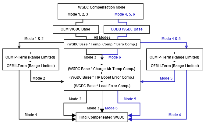
How These Compensations Are Applied
The compensations have a specific order and operation. This is done to ensure that atmospheric and temperature conditions are accounted for at all times. See below for the math that is working behind the scenes! Note that Barometric Pressure and Temperature compensations are always active regardless of the compensation mode.
- WGDC Base * CAT Comp. = CAT Comp %
- WGDC Base * TIP Boost Error Comp. = TIP Boost Error Comp %
- WGDC Base * Load Error Comp. = Load Error Comp % (Note: Load Desired (Tq Ctrl) – Load Actual = Load Error)
- WGDC P-Term = WGDC P-Term % (Now clipped between PID P-Term (Min) and PID P-Term (Max))
- WGDC I-Term = WGDC I-Term % (Still clipped between PID I-Term (Min) and PID I-Term (Max))
Note: We have also added the ability to clip WGDC PI-Error with new tables PID PI-Error (Min) and PID PI-Error (Max).
All of these calculations are done continuously and are combined into the (CCF) WGDC Final monitor according to the active (CCF) WGDC Comp Mode. The (CCF) WGDC Final value will then be clipped between 0-100% and become WGDC Actual.
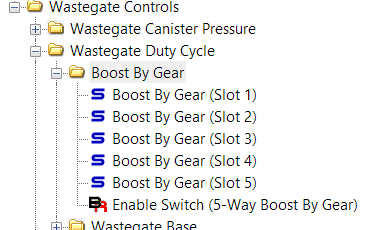
Feature: Boost By Gear
Description
This table allows a throttle based per gear adjustment of wastegate duty cycle. This multiplier will be applied to the final wastegate duty cycle after all other WGDC calculations and compensations.
Dependencies / Requirements
This table requires the Master Switch (CCF WG Features), and the Enable Switch (5-Way Boost By Gear) to be used.
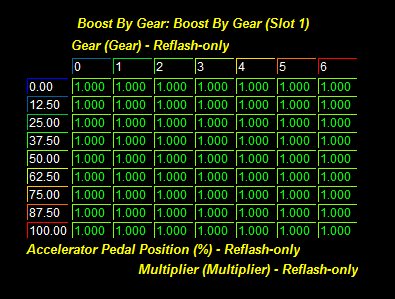
Using This Feature
Once enabled you will be able to customize each individual gear to multiply the final calculation of WGDC by the values provided at any given throttle position. Values of 0 will eliminate WGDC at a given throttle position in the desired gear. A value of 1 will apply no correction, and a value of 1.5 would apply a 1.5 times the final wastegate amount. This can aid in preventing overboost in lower and higher gears. By default all values in the Boost By Gear tables are set to 1.0 (no corrections).
What To Monitor
CCF Monitor Name - (CCF) BBG Multiplier
CCF Monitor Name - (CCF) WGDC Pre-Final
OEM Monitor Name - Accelerator Pedal Position
OEM Monitor Name - Gear Current
OEM Monitor Name - WGDC Actual
Warnings
Please be aware that the OEM P/I dynamics may constantly try to fight this multiplier when in use, so be sure to adjust the P-Term, I-Term, and PI-Error (Max) tables (if applicable) so they play nicely.
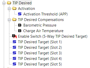
Feature: COBB TIP Desired Target
Description
Once activated, the values in the table will override the OEM dynamic TIP Desired calculations. During this time, the TIP Desired values sent to the bypass valve functions will also be matched to this table.
Dependencies / Requirements
This table will be used when the Enable Switch (5-Way TIP Desired Target) configuration is enabled and the Activation Threshold (APP) threshold has been exceeded.
Using This Feature
Make sure to set the Activation Threshold (APP) value in a range that will permit a smooth transition from the OEM dynamic controls during part throttle to the WOT conditions here. Also note that when using CCF Wastegate Duty Cycle controls, the X-Axis pressure source can be switched to TIP Desired to utilize this table as a feed directly into the CCF WGDC table.
What To Monitor
CCF Monitor Name - (CCF) TIP Ceiling
CCF Monitor Name - (CCF) TIP Ceiling Comp
OEM Monitor Name - Accelerator Pedal Position
OEM Monitor Name - Engine Speed
OEM Monitor Name - TIP Desired Absolute
Warnings
Set this value under the maximum amount of pressure the engine can safely handle with the given fuel and operating conditions. Use the TIP Ceiling to set the absolute maximum pressure.
Standard Strategy (OEM Override Mode)
This strategy was previously added to Accesstuner software and allows for manipulation of the TIP Desired target by use of the scalar/offset pair in the TIP Desired Override folder. To use this method simply check the Enable TIP Desired Override toggle in the Advanced Options menu. When this toggle is enabled, the COBB strategy will not be available.
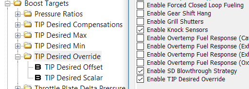
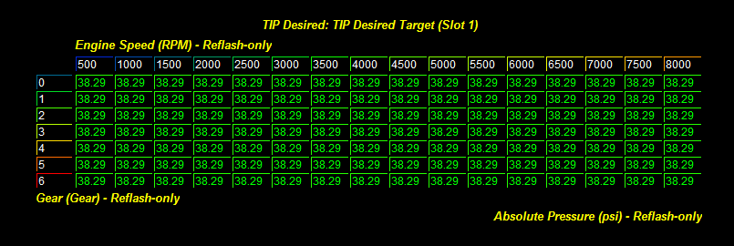
COBB Strategy
The COBB strategy was designed to give greater flexibility of pressure control when using varying calibration strategies. When the COBB Strategy is active, the lookup value from the TIP Desired Target 3D table will act directly as the TIP Desired Absolute and target pressure by means of wastegate and throttle control. When combined with the COBB 5-way WGDC Base, COBB 5-way WGDC Compensations, and COBB 5-way TIP Ceiling; consistent and reliable boost control can be achieved!
To use the COBB strategy simply set the Enable Switch (5-Way TIP Desired Target) to 1.
Target Compensations
Additional tables have been added to allow Barometric Pressure and Charge Air Temperature compensation to the TIP Desired Absolute value. This ensures that targets can be adequately adjusted for varying atmospheric and running conditions. These compensation tables are only active when the Enable Switch (5-Way TIP Desired Target) is set to 1 and the Accelerator Pedal Position is above the Activation Threshold (APP) value. They will not be applied to the OEM operation values.
Monitoring the System
The running output of this feature is fed directly into the OEM functions, therefore no new monitors have been added to watch the table look-ups. Simply monitor TIP Desired Absolute to see the final value.
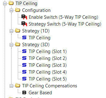
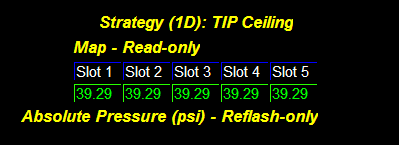
Feature: TIP Ceiling
Description
The maximum amount of pre-throttle pressure allowed prior to throttle closure.
Dependencies / Requirements
This table will be available when the Enable Switch (5-Way TIP Ceiling) and Strategy Switch (5-Way TIP Ceiling) are set to 1.
Using This Feature
Watch the (CCF) TIP Ceiling monitor to verify the current lookup value which will vary with both Accelerator Pedal Position and Engine Speed. When the Strategy Switch (5-Way TIP Ceiling) is set to 0, the 1D TIP Ceiling version of the feature will be used, assuming the Enable Switch (5-Way TIP Ceiling) is still enabled. When the Enable Switch (5-Way TIP Ceiling) is off, the OEM tables will be used.
What To Monitor
CCF Monitor Name - (CCF) TIP Ceiling
CCF Monitor Name - (CCF) TIP Ceiling Comp
OEM Monitor Name - Accelerator Pedal Position
OEM Monitor Name - Engine Speed
OEM Monitor Name - TIP Actual Absolute
OEM Monitor Name - TIP Desired Maximum
Warnings
Set this value to the maximum amount of pressure the engine can safely handle with the given fuel and operating conditions.
Standard Strategy (1D)
This strategy was designed to allow multiple 1D TIP Ceiling values in a single calibration. This value is will override any value in the OEM TIP Desired Max. (Ceiling) table. Once TIP Actual Absolute reaches this value, the throttle will be used to control boost and maintain a steady pressure. To use this feature simply set the Enable Switch (5-Way TIP Ceiling) to 1 and the Strategy Switch (5-Way TIP Ceiling) to 0.
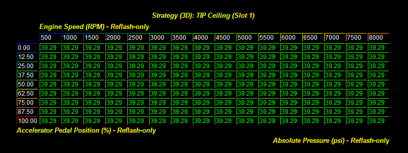
Advanced Strategy (3D)
The advanced strategy was designed to give greater flexibility of pressure control when using varying calibration strategies. When the Advanced Strategy is active, the lookup value from the 3D table will act directly as the TIP Desired Max. (Ceiling) and limit pressure by means of throttle control. When combined with the COBB 5-way WGDC Base, and COBB 5-way WGDC Compensations; consistent and reliable boost control can be achieved!
To use the Advanced Strategy simply set the Enable Switch (5-Way TIP Ceiling) to 1 and the Strategy Switch (5-Way TIP Ceiling) to 1.
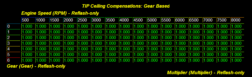
Gear Based Compensation
An additional table has been added to allow gear and RPM based compensation to the ceiling value. This allows for higher per-gear TIP Desired Targets without throttle closures. This table is only active when the Enable Switch (5-Way TIP Ceiling) feature is enabled. It will not be applied to the OEM non 5-way value.
Monitoring the System
To see the running calculations from these tables the following monitor has been added.
(CCF) TIP Ceiling shows the value as looked up from the CCF TIP Ceiling 1D or 3D tables which includes the (CCF) TIP Ceiling Comp multiplier.
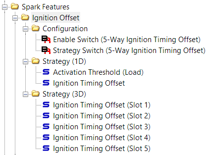
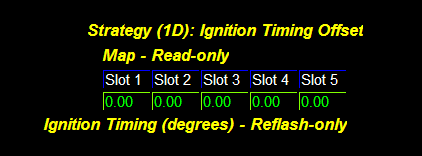
Feature: Ignition Timing Offset
Description
The values in this table are multiplied by the current Octane Adjust Ratio to create a dynamic timing compensation based on octane. This is a custom compensation that has been created to allow even further customization to the ignition timing curve.
Dependencies / Requirements
This 3D table will be available when the When the Enable Switch (5-Way Ignition Timing Offset) and Strategy Switch (5-Way Ignition Timing Offset) are set to 1.
Using This Feature
Watch the (CCF) Ignition Offset monitor to verify the current lookup value which will vary with both Load Actual and Engine Speed. When the Strategy Switch (5-Way Ignition Timing Offset) is set to 0, the 1D version of the feature will be used, assuming the Enable Switch (5-Way Ignition Timing Offset) is still enabled. When the Enable Switch (5-Way Ignition Timing Offset) is off, the OEM table will be used.
What To Monitor
CCF Monitor Name - (CCF) Ignition Offset
OEM Monitor Name - Load Actual
OEM Monitor Name - Engine Speed
Warnings
The application of these values are applied GLOBALLY. This means they can override your ignition timing ceiling or floor! These values do not replace the OEM BL Timing Comp. (OAR) table. Be mindful to consider the use of this table as a supplement to your timing strategy, especially when using multiple fuel types in the 5way slots.
Standard Strategy (1D)
This strategy was designed to give quick and easy adjustments to ignition timing. The desired amount of timing advance (or retard) can be set, along with the minimum load in which to activate the feature. This value is globally applied once active and will override any value in the OEM Ignition Timing Offset (Global) table. Once the load drops below the minimum, the OEM value will be restored. To use this feature simply set the Enable Switch (5-Way Ignition Timing Offset) to 1 and the Strategy Switch (5-Way Ignition Timing Offset) to 0.
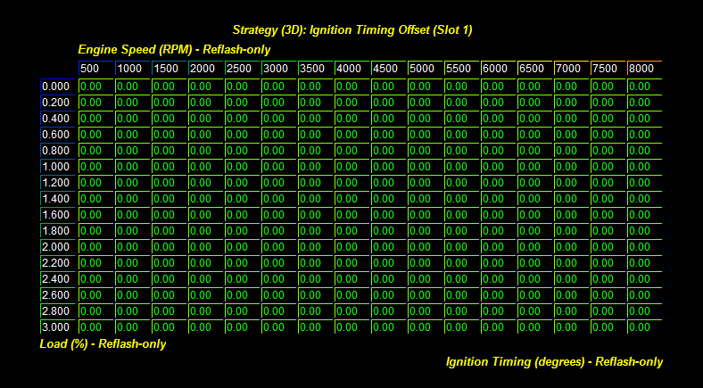
Advanced Strategy (3D)
The advanced strategy was designed to give dynamic ignition timing flexibility based on octane for those who are tuning for different fuel types, or live in areas where fuel quality varies from tank to tank. While the table is similar to the OEM BL Timing Comp. (OAR) in design, it is not limited in application or resolution. The OEM table applies only to Borderline Timing and can be clipped by the timing floor or ceiling. The COBB table is globally applied and can bypass the timing floor or ceiling. When the Advanced Strategy is active, the lookup value from the 3D table will be multiplied by the Oct. Adj. Ratio Learned value before being applied to the ignition timing calculations.
This table will run in tandem with the OEM BL Timing Comp. (OAR) values so be mindful when shaping your ignition timing curves that both will be active when this feature is enabled. With the following system in place, a single calibration file can provide dynamic performance settings for any fuel type!
To use the Advanced Strategy simply set the Enable Switch (5-Way Ignition Timing Offset) to 1 and the Strategy Switch (5-Way Ignition Timing Offset) to 1.
Monitoring the System
To see the running calculations from these tables the following monitor has been added.
- (CCF) Ignition Offset shows the value that will be globally applied to ignition timing.
Note: When the Standard Strategy is active, this monitor will show the exact value from the 1D table.
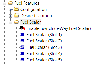
Feature: Fuel Scalar
Description
This value is used to adjust the target stoichiometric AFR for fuel calculations. Tuning for different fuel types on a single calibration is now a reality! With the addition of the "Fuel Scalar" to the 5-way assortment, you can now run pump gas, race gas, or varying blends of E85 with ease.
Dependencies / Requirements
When the Enable Switch (5-Way Fuel Scalar) is set to 1, use this feature to test multiple fuel scalar changes in a single reflash to speed up dyno tuning or to allow multiple fuel types in a single calibration.
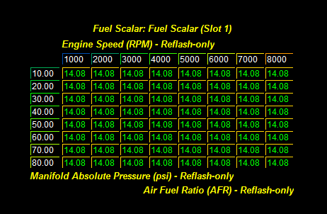
Using This Feature
When the Enable Switch (5-Way Fuel Scalar) is set to 0, the Fuel Scalar Stoich. Setpoint (OEM) can be adjusted in realtime.
When the Enable Switch (5-Way Fuel Scalar) is set to 1, the CCF Fuel Scalar table will be used for value lookup and realtime adjustability of the Fuel Scalar Stoich. Setpoint (OEM) will be disabled. The 3D table is referenced by Engine Speed and Manifold Absolute Pressure.
The Enable Switch (5-Way Fuel Scalar) is adjustable in realtime and can be used to test the lookup behavior of both OEM and CCF tables.
What To Monitor
CCF Monitor Name - (CCF) Fuel Scalar
OEM Monitor Name - Engine Speed
OEM Monitor Name - Manifold Absolute Pressure
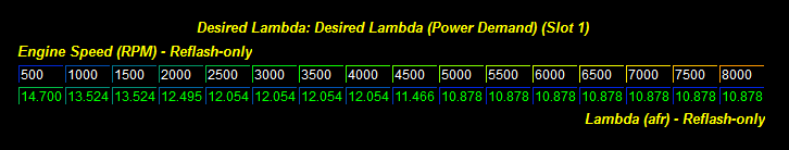
Feature: Power Demand Fuel
Description
This setting will enable the use of the CCF 2D Desired Lambda (Power Demand) fuel table instead of the factory ECT based table.
Using This Feature
When the Enable Switch (5-Way Power Demand Fuel) is set to 0, the (CCF) Desired Lambda PD monitor value will match the Desired AFR (Power Demand) monitor and be sourced from the Desired Lambda (Power Demand) (OEM) table. The OEM table uses both Engine Speed and Coolant Temperature as a lookup and essentially becomes a 2D table once the engine is warmed up.
When the Enable Switch (5-Way Power Demand Fuel) is set to 1, the CCF Desired Lambda (Power Demand) table will be used for value lookup. The CCF table is referenced by Engine Speed only.
The enable switch is adjustable in realtime and can be used to test the lookup behavior of both OEM and CCF tables.
What To Monitor
CCF Monitor Name - (CCF) Desired Lambda PD
OEM Monitor Name - Engine Speed
OEM Monitor Name - Coolant Temperature
OEM Monitor Name - Desired AFR (Power Demand)
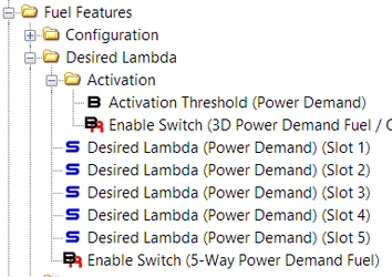
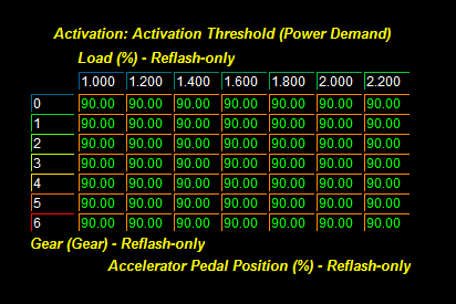
Feature: Power Demand and VCT OP Thresholds
Description
Another COBB exclusive set of tables has been added to the ECU to enhance the resolution of these two control systems. Fueling transitions between closed loop and power demand, as well as VCT transitions into Optimum Power were previously handled by less than desirable 2D tables (OEM VCT OP shown below). We felt these tables caused abrupt activation and could use some help. Each of these thresholds now has a brand new 3D table (COBB VCT OP shown below) that is indexed by Gear Current and Load Actual to better aid in transitioning for realistic requirements for each gear.
Dependencies / Requirements
- To use the 3D tables, activate the Enable Switch (3D Power Demand Fuel / OP VCT APP Thresholds). When not activated, the OEM 2D tables will be used
- Note: this switch is in both Fuel and VCT folders for visibility, when enabled, both 3D tables will be activated.
- Adjust the Activation Threshold (Power Demand) and Activation Threshold (Optimum Power VCT) tables as desired.
Using This Feature
Once configured and calibrated the tables will work seamlessly to handle the transition into Power Demand / Optimum Power modes.
What To Monitor
(CCF) APP Threshold VCT – The minimum throttle position required to activate “Optimum Power” VCT mode.
(CCF) APP Threshold PD – The minimum throttle position required to activate power demand fueling.
Warnings
Please take the time to dial in these tables for optimal results. Our OTS maps are a great starting point but can be refined further for your own driving style or modifications.
OEM Table
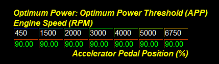
CCF Table
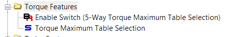
Feature: Torque Maximum Table Selection
Description
As our tuning strategies continue to evolve, we are able to isolate and enhance certain useful tables that aid in the control of engine power. This is the example of that process. Most of the OEM EcoBoost calibrations come with an "Overboost" feature that is pre-configured to delivery a burst of additional power for a chunk of time. This feature has been refined over time by Ford, and has ended up with a few tables that were not being leveraged.
Understanding this logic, and using the knowledge to drive this custom feature has netted the capability of selecting between the available table pairs on-the-fly using our 5-Way Map Switching.
Activating this feature will allow the COBB 5-Way Map Switching feature to toggle between the OEM Torque Max. with Overboost and Torque Max. without Overboost tables. The OEM implementation only allows for a single setting to be active at all times by means of the configurations made in Torque Max. Configuration. By enabling this feature, the OEM single value will be ignored, and the setting in each active map slot will be used instead.
For a good explanation of the OEM Overboost features see this great post by Steven Goldade.
Dependencies / Requirements
- Activate the Enable Switch (5-Way Torque Maximum Table Selection) to utilize this feature.
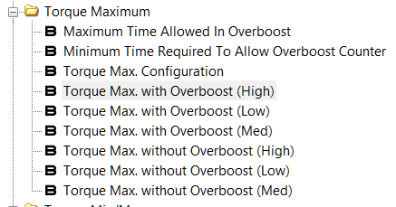
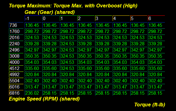
- Modify the appropriate Torque Max. with Overboost and Torque Max. without Overboost tables as desired.
- Adjust the Maximum Time Allowed In Overboost and Minimum Time Required To Allow Overboost Counter as desired.
Using This Feature
When configured, the vehicle will automatically use the pair of tables desired when running with or without overboost. Use this feature to test multiple engine torque targets in a single reflash to speed up dyno tuning.
What To Monitor
Overboost Available – Status indicator for the Overboost feature, a value of 1 means available.
Overboost Counter – The time since Overboost became active, this can count up or down.
LTT Torque Final – Engine brake torque measured by incoming airflow, includes all compensations for torque loss from accessories, friction, etc.
Torque Maximum (CVC) – The maximum amount of engine torque allowed by the CVC.
Warnings
Be aware of the impact additional torque will have on the engine and set your overboost time limits appropriately.
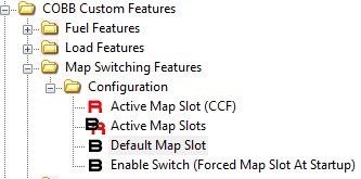
Feature: Default Map Slot
Description
When using the COBB 5-Way Map Switching feature, the default map slot can be set via calibration. This allows for the vehicle to be configured to a specific set of parameters when it is first started. The feature allows for a forcing of the slot as well during every startup.
Dependencies / Requirements
- The Default Map Slot must be set to a value equal or less than the number of Active Map Slots. If it is outside of the range, the lower of these two values will be defaulted.
- If desired, set the Configure Forced Map Slot On Startup to always use the Default Map Slot every time the car is started.
Using This Feature
Once the configuration settings are applied the Default Map Slot will be used each time the ECU has been reflashed or reset. Once the vehicle has been driven, the next startup will restore the map slot the vehicle was shut off with (unless the forced option is set).
What To Monitor
(CCF) Map Slot - Current active map slot
Warnings
Make sure to check all settings that are used in the map slot designated as default. Vehicles running different fuel types may be at risk for damage if settings are too aggressive for the fuel type being used.
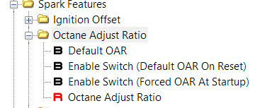
Feature: Default OAR
Description
This feature was designed to allow the vehicle to run a specific OAR value when reflashed or reset. Additionally, we added an ability to set this value each time the car is started.
See our tech article for a better understanding about what OAR is! (Tech Bulletin - Octane Adjust Ratio)
Dependencies / Requirements
- To activate this feature for all reset and reflash conditions use the Enable Switch (Default OAR On Reset) table.
- To activate this feature ALL startups use the Enable Switch (Forced OAR At Startup) table.
- Set the OAR value by using the Default OAR table.
Using This Feature
Once the configuration table is activated the value set in the Default OAR table will be used. Once the vehicle has been driven and conditions are met for the learned OAR to be stored, the next startup will restore the previous OAR value the vehicle was shut off with.
The Octane Adjust Ratio can also be adjusted in realtime once live connected to the vehicle with Accesstuner.
What To Monitor
Oct. Adj. Ratio Learned – Octane adjust ratio learned. -1.0 is HIGH fuel quality, 1.0 is LOW fuel quality.
Warnings
Setting the OAR to -1.0 or similar on vehicles that are running low octane fuels may cause knock. The learning portion of this system takes time to adjust, so please set this value accordingly for the fuel used.
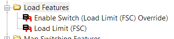
Feature: Extended Load Limit
Description
Previously, the ECU code had a hard coded limit that could prevent high power builds from achieving higher than 3.0 load values. We have re-written this logic to allow for a user defined hard limit.
Dependencies / Requirements
This limiter is only active when the Enable Switch (Load Limit (FSC) Override) table is enabled.
Using This Feature
Once the configuration table is activated, simply set the Load Max. (FSC) value.
What To Monitor
Load Limit (FSC) – The currently used load limit from the fail-safe cooling measurements.
Warnings
Please note that this limit is also used in calculations when the vehicle overheats and triggers fail-safe cooling.
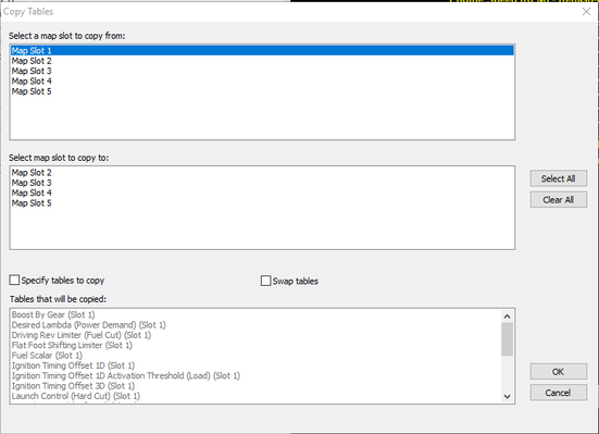
Feature: Map Slot Copy
Description
To aid in the tuning process we have added a copy feature to the software. This feature can be accessed by selecting "Edit" -> "Copy Tables" or by using the CTRL+Shift+C hotkey. This feature is helpful when utilizing similar settings between map slots or making changes that need to be populated to all slots.
Dependencies / Requirements
None, this is a TUNER feature!
Using This Feature
- First, select the source slot for copying from the top list. In the example we have selected "Switchable Map 1" as our source.
- Next, select the target slots to be populated from the bottom list.
- Then decide whether all eligible tables or individual tables should be copied. If all tables are desired, leave the "Specify tables to copy" box unchecked. If individual tables are desired place a check in the box and select the desired tables to be copied.
- If you want to swap tables between two map slots you can simply check the "swap tables" box.
In this example we only want to copy the "TIP Desired Max. (Ceiling) 3D" and "WGDC Base" tables to map slots 2 and 5.
Once everything is ready to copy, simply click OK to proceed and verify your results.
Warnings
As a precaution, it is always recommended to check over any changes before saving, and flashing any map after using this feature.
Related content
Copyright 2025 © COBB Tuning Products LLC. All Rights Reserved. | www.cobbtuning.com