V3 Accessport Ford User Manual
- Will Trang
- Brandyn Mowat
- Former user (Deleted)

Accessport
Ford User Guide
Product Introduction
Congratulations on the purchase of the Accessport handheld programmer. The Accessport is the industry leading OEM ECU flashing, managing and monitoring assistant. Unlock power hidden within the ECU by replacing conservative factory settings with more aggressive calibrations. The result is impressive gains in torque and horsepower while maintaining a high degree of safety. The Accessport can:
- Reprogram the factory engine control unit (ECU) with improved tuning parameters through the on-board diagnostic (OBD-II) port.
- Monitor and log vehicle sensor data using on-screen digital gauges.
- Read and clear engine diagnostic trouble codes (DTCs).
- Measure 0-60mph, and ¼ mile times.
In-Box Contents

WARNING! |
|---|
| Installation and use of the Accessport may void all or a portion of the vehicle manufacturer's standard warranty. There is no guarantee expressed or implied by COBB Tuning or any of its affiliates for the use of the Accessport. The user accepts all risks and responsibilities when using the Accessport. |
| WARNING! |
|---|
| Use of the Accessport while operating a moving vehicle is strictly prohibited by law. COBB Tuning and its affiliates accept no responsibility for damages or injury caused by misuse of the Accessport. |
| WARNING! |
|---|
| The Accessport may not be able to function if the vehicle's wiring has been modified. If problems occur while using the Accessport, please verify that all wiring to and from the ECU is correct and functional. |
Accessport Installation:
Mounting Options
A universal 'sticky' mount is included with the Accessport. For the best results, we recommend installing the mount vertically, and preparing the mounting surface with the included alcohol wipe.
- NOTE: It's important to note that not all surfaces provide a strong adhesive bond.
- NOTE: The Accessport cradle is compatible with "Dual T" style mounts.
Pre-Installation
The Accessport comes with the most up-to-date software and map files available at the time of shipment. However, it is possible that updated software and/or map files have been made available since the time of shipment. Therefore, the recommended procedure is to connect the Accessport to the AP Manager software and download the latest firmware for the target vehicle. Please visit www.cobbtuning.com/apmanager to download AP Manager and to find a link for the AP Manager manual.
If you have issues transferring maps or updating the Accessport while using USB 3.0 ports, please try using a USB 2.0 hub adapter.
NOTE: The Accessport is preloaded with a default set of maps for all cars that it supports. This may include but is not limited to Stage1, Stage2, Stage3 (all octanes), Anti-theft, Economy, and Valet. If you would like to view all maps available you can visit the Ford Tab in the Maps section of our website.
| IMPORTANT! |
|---|
Before installing the Accessport on the vehicle, it is important to verify that the vehicle is adequately prepared for the installation process. Since the Accessport uses the vehicle’s battery for power and the ECU reprogramming process requires adequate battery power as well, it is critical to verify that the vehicle’s battery has a good charge. This can be done through the use of a battery charger/conditioner or by driving the vehicle for a period of time prior to installation to allow the alternator to recharge the battery. Furthermore, please ensure that all in-car electronic devices are turned off to reduce power draw on the battery. This includes car stereos, video screens, GPS units, radar detectors, interior and exterior lights, and any other electronic device that uses the car battery for power. |
Screen Capture
Screenshots can be captured by holding down the [CANCEL] button for two seconds. Any stored screen captures can be retrieved by using Accessport Manager.
Getting Started
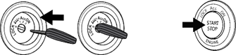
1. You will need the Accessport and OBD-II cable to perform the installation. Insert the key into the vehicle’s ignition and leave it in the OFF position. For keyless cars, make sure the vehicle is in the OFF state.
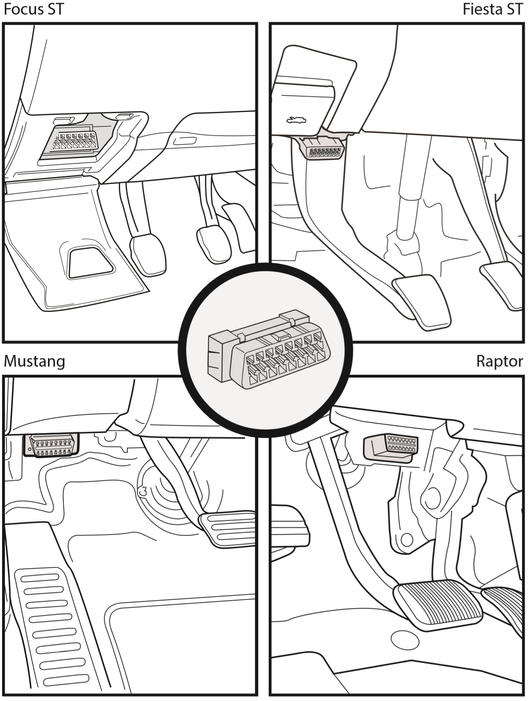
2. Locate the vehicle's OBD-II port. Location of the OBD-II port may vary depending on the vehicle model. The Focus ST has a covered OBD-II port shown below in “Image1”. The Fiesta ST is located just under the plastic trim behind the hood latch release (see Image2).
The following steps 2.1 – 2.4 are optional install steps for the Ford Focus ST model only. Optional steps are intended for dash mounted Accessports and ultimately present a cleaner cable routing solution.
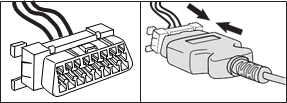
2.1. Optional install: Locate the clips on the sides of the OBD-II port.
2.2. Optional install: Remove the OBD-II connector port from the harness by pressing the clips in and releasing the OBD-II port from the harness.
2.3. Optional install: Plug the OBD-II cable into the OBD-II port under the dash of the vehicle.
2.4. Optional install: Tuck the OBD-II connector port back into the dash, above the harness and close the panel.
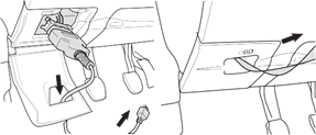
Plug the OBD-II cable into the OBD-II port in the dash of vehicle.
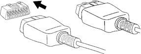
3. Connect the small end of the OBD-II cable to the port on the bottom of the Accessport

4. Make sure the clasp on the OBD-II cable firmly engages with the port.

5. Turn the key to the ON position but do not start the vehicle. Turn off all in-car electronics (AC/heater fans, headlights, stereo, etc.) and make sure all doors are shut. For keyless cars, make sure your feet are free from all pedals and press the start button once.
NOTE: The engine should not be running.

6. Select [Install] from the Accessport menu by pressing the [OK] button to proceed with installation.

Vehicle Identification
The Accessport will attempt to automatically determine the target vehicle for installation. Verify that the identified vehicle is correct and press [OK] to confirm.
If an error occurs:
Please refer to the Troubleshooting Section.
What Is A Map?
The Accessport reprograms the factory tuning parameters inside the engine control unit (ECU) using map files, which contain specially written instructions for the Accessport to follow during the reprogramming process. A map file can contain information for any number of different modifications or enhancements to a vehicle, ranging from a race map for heavily modified vehicles, to an economy map for a stock vehicle. Through the use of the Accessport and different map files the ECU can be reprogrammed to accommodate virtually any vehicle configuration.
Map Selection
After the Accessport identifies the vehicle, it will present a list of maps. Maps that are not intended for the identified vehicle are displayed in gray. The Accessport will reprogram the ECU with the calibration data from the map selected for installation. This will become the base data for the ECU. To ensure the best performance, select the map that most closely matches the modification level of the vehicle.
If you are unsure about which map applies to your modification level, please see the Focus ST map notes or the Fiesta ST map notes and their requirements for the modifications that will best fit your vehicle.
Select a map and press [OK] to proceed with the installation. If you wish to see a longer description for the highlighted map, press and hold the [OK] button on the desired map.
| WARNING! |
|---|
If a previous installation of an Accessport is detected, you will be given the option to overwrite it with a new installation. Be aware that the previous installation will be permanently lost and unrecoverable. In the case of a previous install, a stock ECU program supplied on the Accessport will be used when you uninstall. |
Install Accessport Programming
The Accessport will automatically proceed with installation to the vehicle. At this point the Accessport reprograms the vehicle's ECU with new program data and calibration parameters from the installation map file.
| WARNING! |
|---|
| Do not disturb the Accessport and the OBD-II connector while installation is taking place. Failure to do so may result in incomplete ECU reprogramming which will render the vehicle inoperable. If an error occurs during the reflash, the Accessport will enter Recovery Mode and attempt to recover the reflash. |
Installation Complete
Follow all on-screen prompts on the Accessport to complete the installation process. The Accessport is now fully installed and ready for use and the vehicle's ECU and TCM, if applicable, are now programmed with new calibration data. The Accessport does not need to be plugged into the vehicle for the calibration to be in effect. You can disconnect the Accessport at this time or leave it plugged in to use any of the many features outlined below.
Please note that the Accessport is designed to work with only one vehicle at a time. Once the Accessport is installed, it cannot be used with another vehicle until it is uninstalled from the original vehicle.
CARB Sticker Application
(Where Applicable)
Apply the supplied CARB sticker in a clear, easy to find location. Typically underhood, or on the radiator core support.
Accessport Features & Functionality

Gauges
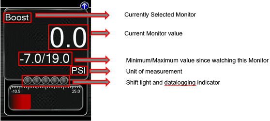
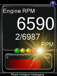
The Accessport can read sensor data from the factory ECU and display it as an on-screen gauge. This feature allows the Accessport to function as an auxiliary gauge displaying boost, RPM, temperature, or any number of other parameters available in the factory ECU.
The Accessport can also record sensor data from the factory ECU while you drive. With the ability to store multiple sessions, the Accessport can function as a complete engine datalogger and diagnostic tool. To begin datalogging, press the [OK] button while in the Gauges function. While the Accessport is recording a datalog, a single light blue light will scroll in the shift light. To view the results of your datalog sessions, simply connect the Accessport to your PC and retrieve the results using the AP Manager software. Data Log recordings are stored in a .csv (Comma Separated Values) format and are easily viewed using any spreadsheet application.
When you first select the Gauges function, you will be prompted to select an initial gauge layout. This layout can be changed at any time from the Change Gauge Layout menu.
Press the [Up] or [Down] button to bring up the header. Then press the [Down] button to highlight the monitor you would like to interact with and press [OK]. You will then be presented with the following options.
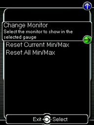
Change Monitor – Select the monitor that will be shown in the selected gauge
Note: While in the Change Monitor list, you can press [UP] to find a Sort Monitors option. This option will sort all monitors in reverse alphabetical order.
Reset Current Min/Max – Reset the minimum and maximum values of the selected gauge
Reset All Min/Max – Reset the minimum and maximum values of all gauges
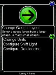
Change Gauge Layout – Select a gauge layout from a single large gauge, to many small gauges
Change Units – Set the unit scheme
Configure Shift Light – Adjust the RPM of the Shift Light
Configure Datalogging – Select which monitors to datalog
Change Gauge Layout
You have the ability to display between 1 – 6 gauges in different preset formats. The formats are as follows:

One Gauge
- One large Digital Gauge w/ Bar Gauge
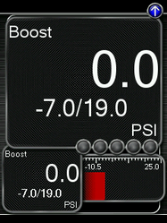
Two Gauges
- One large Digital Gauge
- One small Digital Gauge w/ Bar Gauge
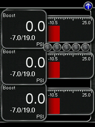
Three Gauges
- Three small Digital Gauges w/ Bar Gauges
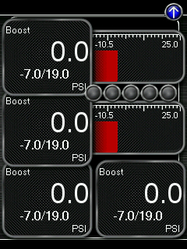
Four Gauges
- Two small Digital Gauges w/ Bar Gauges
- two small Digital Gauges
Five Gauges
- One small Digital Gauge w/ Bar Gauge
- four small Digital Gauges
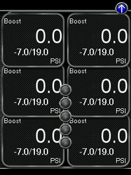
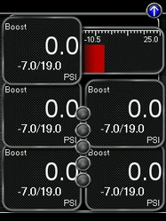
Six Gauges
Six small Digital Gauges
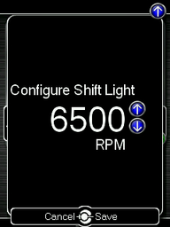
Configure Shift Light
![]()
Press [OK] and using the [Up] and [Down] buttons, set the RPM to the desired level to have the shift light flash. Press [OK] to save the RPM you have selected. By default, the shift light RPM is set above the stock redline. This essentially disables the shift light since that RPM will not be reached. You will need to lower the shift light RPM to enable this feature.
Press [UP] to find the Setup option for the Shift Light, where you will find the following options:
Disable Shift Light – Disables the shift light function and removes the shift light from the gauges screen.
- NOTE: When you initiate a datalog, the shift light will reappear to notify you that you are logging.
Reset Shift Light – Resets the shift light back to the default value.
Configure Datalogging
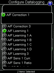
This list allows the user to enable or disable parameters for logging. Only monitors with a green circle will be recorded while using the datalogging feature. There is a default log list that includes a group of monitors put together by our in-house tuners. You can make changes to the log list by highlighting a monitor and pressing the [OK] button to activate/deactivate it for logging. Pressing the [Cancel] button will save any changes you have made to the datalog list.
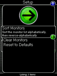
Press [UP] to find the Setup option for Configure Datalog where you will find the following options:
Sort Monitors – Sort the monitor list alphabetically, then reverse-alphabetically
Clear Monitors – Clear all monitors from the datalog list
Reset to Defaults – Restore the datalog list to the default list
NOTE: You will be notified if you have exceeded the recommended amount of monitors to record in one datalog. If you receive this prompt, reduce the amount of monitors you are recording.
NOTE: The Accessport is only capable of datalogging while the ignition is turned to the ON position. The Accessport will display an error message if it cannot communicate with the vehicle.
NOTE: Up to 10 log files can be stored on the Accessport. Use AP Manager to delete unneeded logs. If datalogging is started when there are already 10 log files on the Accessport, the log file with the lowest numerical value will be automatically overwritten.
NOTE: The 10 log files can be a combined length of 2+ hours long.
Performance

The Accessport can calculate several performance measurements.
NOTE: The Accessport is only capable of calculating performance test results while the ignition is turned to the "ON" position. The Accessport will display an error message if it cannot communicate with the vehicle.
NOTE: Performance Menu is not available in AP3-FRP-001 (Ford Performance 2.3L EcoBoost ECU) - vehicle speed sensor input is not available.
0-60 MPH
To record the 0-60 MPH performance, select this menu option and follow instructions. A time slip showing the performance results will be displayed at the end of the performance test.
¼ Mile
To record the ¼ Mile performance, select this menu option and follow instructions. A time slip showing the performance results will be displayed at the end of the performance test.
Press [UP] to find the Setup option for Performance where you will find the option to Change Units.
Change Units
Imperial – This unit scheme uses imperial units: F, mph, PSI, AFR
Metric w/ AFR – This unit scheme uses metric units (excl. AFR): C, kph, kPA, AFR
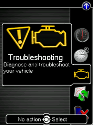
Troubleshooting

Use the Accessport as a diagnostic tool.
NOTE: The Accessport is only capable of communicating with the ECU while the ignition is turned to the "ON" position. The Accessport will display an error message if it cannot communicate with the vehicle.
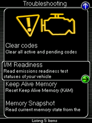
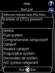
I/M Readiness
Use this feature to read Inspection / Maintenance (I/M) test statuses of your vehicle. To read I/M, Select Troubleshooting from the main menu. Then, scroll to I/M Readiness. You will see an extensive list of readiness monitors.
Identify Vehicle
Identifies the year, make, and model of your vehicle.


Reset KAM (Keep Alive Memory)
All Ford Models:
- KAM (Engine) - Reset - Use this function to reset all the vehicles learned parameters (Fuel trims, Idle trims, Etc.).
Ford Models equipped with Automatic (AT) modules only:
- KAM (Trans) - Clear Tables - Clear Transmission Adaptive KAM Tables
- Recommended when transmission shifting becomes abnormal.
- KAM (Trans) - Initialize Tables - Initialize Transmission Adaptive KAM Tables
- Use init. tables when tuning changes have occured and tables were previously cleared.
- KAM (Trans) - Pause Learning - Pause Transmission Adaptive Learning
- Limited to 1 operation per key cycle for diagnosing intermittent problems.
- KAM (Trans) - Reset Learning - Reset Transmission Adaptive Learning
- KAM (Trans) - Stop Learning - Stop Transmission Adaptive Learning
- Limited to 1 operation per key cycle for diagnosing intermittent problems.
Read Codes
Use this function to read trouble codes from the engine computer. Stored codes indicate a mechanical or electrical fault. Use the up/down buttons to highlight a code and display a short description of the trouble code (if available).
Reset ECU
Reset learning and clear codes from the ECU
NOTE: Using the Reset ECU function will not reset any learned parameters (such as fuel trims). If you need to reset the ECU’s learned parameters you can perform a Reset KAM using the designated function. Note that flashing maps with the Change Map function will not reset the learned parameters; they will persist until a Reset KAM function is performed.
Tune

Enhance the performance of your car.
Adjustments
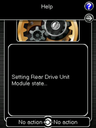
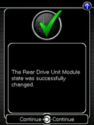
- Disable RDU Module - (AP3-FOR-004 ONLY) - Disables Rear Drive Unit Module
- Enable RDU Module - (AP3-FOR-004 ONLY) - Enables the Rear Drive Unit Module
Note: AP3-FOR-004 Accessport shown |
|
|
|
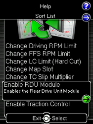

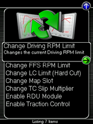
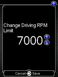
- Change Driving RPM Limit - (AP3-FOR-001 / AP3-FRP-001 / AP3-FOR-004 ONLY) - Changes the current Driving RPM limit.
Note: AP3-FOR-004 Accessport shown |
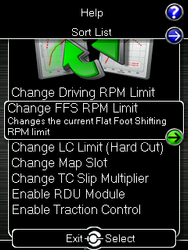
|
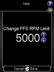
- Change Flat Foot Shifting (FFS) RPM Limit (MT only) - (AP3-FOR-001 / AP3-FOR-004 ONLY) - Changes the current Flat Foot Shifting RPM limit.
Note: AP3-FOR-004 Accessport shown |
|
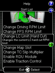
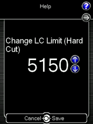
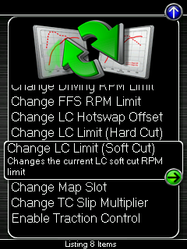
Change Launch Control (LC) Limit (Hard Cut) - (AP3-FOR-001 / AP3-FOR-004 ONLY) Changes the current Launch Control Hard Cut RPM limit.
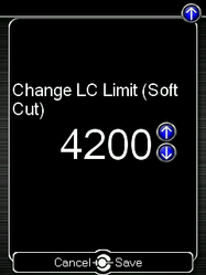
Change Launch Control (LC) Limit (Soft Cut) - (AP3-FOR-001 ONLY) Changes the current Launch Control Soft Cut RPM limit.
Note: AP3-FOR-004 Accessport shown |
|
Note: AP3-FOR-001 Accessport shown |
|
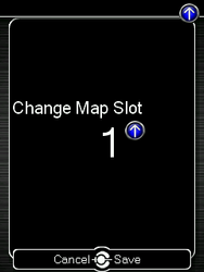
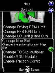
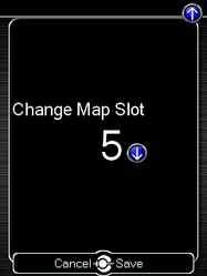
- Change Map Slot - (AP3-FOR-001 / AP3-FRP-001 / AP3-FOR-003 / AP3-FOR-004 ONLY) - Changes the active calibration Map Slot currently being used.
- Adjustment range from 1 to 5 depending on calibration flashed to the ECU.
|  |
|
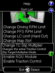
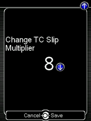
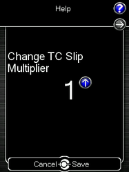
- Change TC Slip Multiplier - (AP3-FOR-001 / AP3-FOR-003 / AP3-FOR-004 ONLY) - Changes the active Traction Control Slip Target Multiplier Mode
- Adjustment range from 1 to 8 depending on calibration flashed to the ECU.
Note: AP3-FOR-004 Accessport shown |
|
|
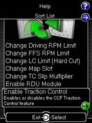
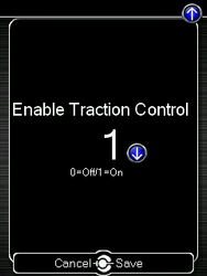
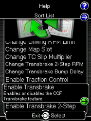
- Enable Traction Control - (AP3-FOR-001 / AP3-FOR-003 / AP3-FOR-004 ONLY) - Changes the active CCF Traction Control state (0=Off/1=On).
Note: AP3-FOR-004 Accessport shown | 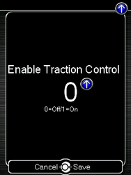 |
|
- Enable Transbrake / Transbrake 2-Step - (AP3-FOR-003 ONLY)
- See COBB Custom Features: EcoBoost Transmission Brake and Bump Box for details
- See COBB Custom Features: EcoBoost Transmission Brake and Bump Box for details
|
| Note: AP3-FOR-003 Accessport Shown |
Change Map
To change the mapping on your ECU, select this menu option and follow the instructions. The ignition must be turned to the “ON” position with the engine off during the Change Map operation. You will be prompted to select a pre-loaded map. The same warnings that apply to the installation process apply here as well (battery charge level, turn accessories off, etc.)
NOTE: If you wish to see a longer description for the highlighted map, press and hold the [OK] button on the desired map.
Restore OTS Map
Select this option to Restore COBB Off-The-Shelf Maps that have been deleted from the Accessport.
Show Current Map
To see the last map that was flashed to your car, select this menu option. You can press the [OK] button to see a detailed description of the map.
Uninstall
Selecting this option will remove the Accessport programming from the vehicle on which it is installed and return the ECU back to a stock state. It is highly recommended to uninstall the Accessport prior to taking your car to the dealer for any type of service. It is also crucial that you uninstall your Accessport if you plan on selling your vehicle or Accessport separately. Otherwise the Accessport will be locked to your vehicle and cannot be used on another car.
User Tools

Expose ECU data
If AP Manager is unable to find the stock data on your Accessport, this function can be used to expose any saved ECU data so that it can be backed up in AP Manager.
Import ECU data
This function will allow you to import ECU data from AP Manager.
Setup
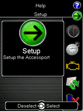
To enter the Setup function, press the [Up] button to bring up the header above the Gauges icon. From here you will have access to the following options:
Auto On/Off Settings – Enable this feature and your Accessport will power on and off with your vehicle.
- Enable Auto On/Off – This will enable the Auto On/Off Feature.
- Enable Low Battery Shutdown – This will shut the Accessport down if battery voltage drops below 10v.
Change Language – Choose from an array of various languages (Note that not all menu entries are translated).
Change Units – Choose from Standard, Metric, and Metric with AFR.
Reset to Defaults – Reset all user settings back to default.
Help
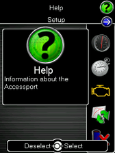
To enter the Help function, press the [Up] button to bring up the header above the Setup icon. From here you will have access to the following options:
About Accessport:
Displays technical information about the Accessport.
- Firmware
- Part Number
- Serial Number
- Installation State
- Vehicle
Context Help: Shows more information about the screen you are currently viewing.
Button Help: Displays the button map.
Icon Help: Displays the various icons you will find on the Accessport.
Demo Mode: This function allows you to run through a mock installation and see all of the features of the Accessport without needing to be connected to a vehicle.
Recovery Mode

If an error occurs during a reflash the Accessport and ECU will enter recovery mode. By selecting this option the Accessport will recover itself to the last selected or installed map.
NOTE: For Recovery Mode to function correctly, you will need to ensure that whatever condition caused the initial failure of the reflash is resolved. For example, if your battery voltage dropped too low during the reflash, put a battery charger on the car before attempting to use Recovery Mode.
Accessport Troubleshooting
Symptom | Troubleshooting Steps |
Accessport will not communicate with vehicle. |
|
Accessport cannot identify vehicle during installation. |
|
Technical Support Contact Information
Web | |
Phone | (866) 922-3059 |
Environmental Information
Operating and Storage Temperatures
The Accessport is designed to be operated at temperatures between 32° and 95° F (0° and 35° C) and with a relative humidity below 90%. Using the Accessport outside of these recommendations may result in damage.
The Accessport is thermally protected and will not function if the temperature reaches extremely high levels. If the Accessport is not booting up correctly or the screen does not show everything correctly, turn the device off and move it to a cooler environment temporarily.
When storing the Accessport, do so in a place where temperature is always between 0° and 115° F (-18° and 46° C) and a relative humidity below 90%.
Never store your Accessport in an area that receives direct sunlight.
Do Not Get The Accessport Wet
Take care to prevent any liquids from coming in contact with the Accessport or any associated equipment.
If your Accessport or any associated equipment gets wet, professional repair may be required. In such cases, please contact Technical Support BEFORE attempting to the use the Accessport.
Handling and Storage
Your Accessport may be damaged by improper storage or handling. Be careful not to drop your Accessport or any associated parts.
Never store your Accessport in an area that experiences any noticeable levels of vibration, static electricity, heat shock, or excessive swings in relative humidity.
Do Not Attempt Repairs Yourself
Never attempt to open your Accessport or any associated equipment. Doing so puts the components at risk of damage from, but not limited to, static shock. No user-serviceable parts are inside. At no time will ANY authorized representative of COBB Tuning, Inc. ask you to open or mechanically/electronically alter the Accessport.
Opening the Accessport will void any and all warranties for the device and its operation.
Related content
Copyright 2025 © COBB Tuning Products LLC. All Rights Reserved. | www.cobbtuning.com