3V2650 - MQB Flex Fuel Kit
- Brandyn Mowat
- Former user (Deleted)

3V2650 – VW Flex Fuel Upgrade Kit
USDM GTI MK7, 7.5 2015-2021
USDM Golf R MK7, 7.5 2016-2019
USDM GLI A7, 2019-2021
USDM A3 2015-2021
USDM S3 2015-2020
Congratulations on your purchase of the COBB Tuning MQB Flex Fuel Kit! The following instructions will assist you through the installation process. Please read them BEFORE beginning the install to familiarize yourself with the steps and tools needed. If you feel you cannot properly perform this installation, we HIGHLY recommend you take the vehicle to a qualified and experienced automotive technician.
Table of Contents
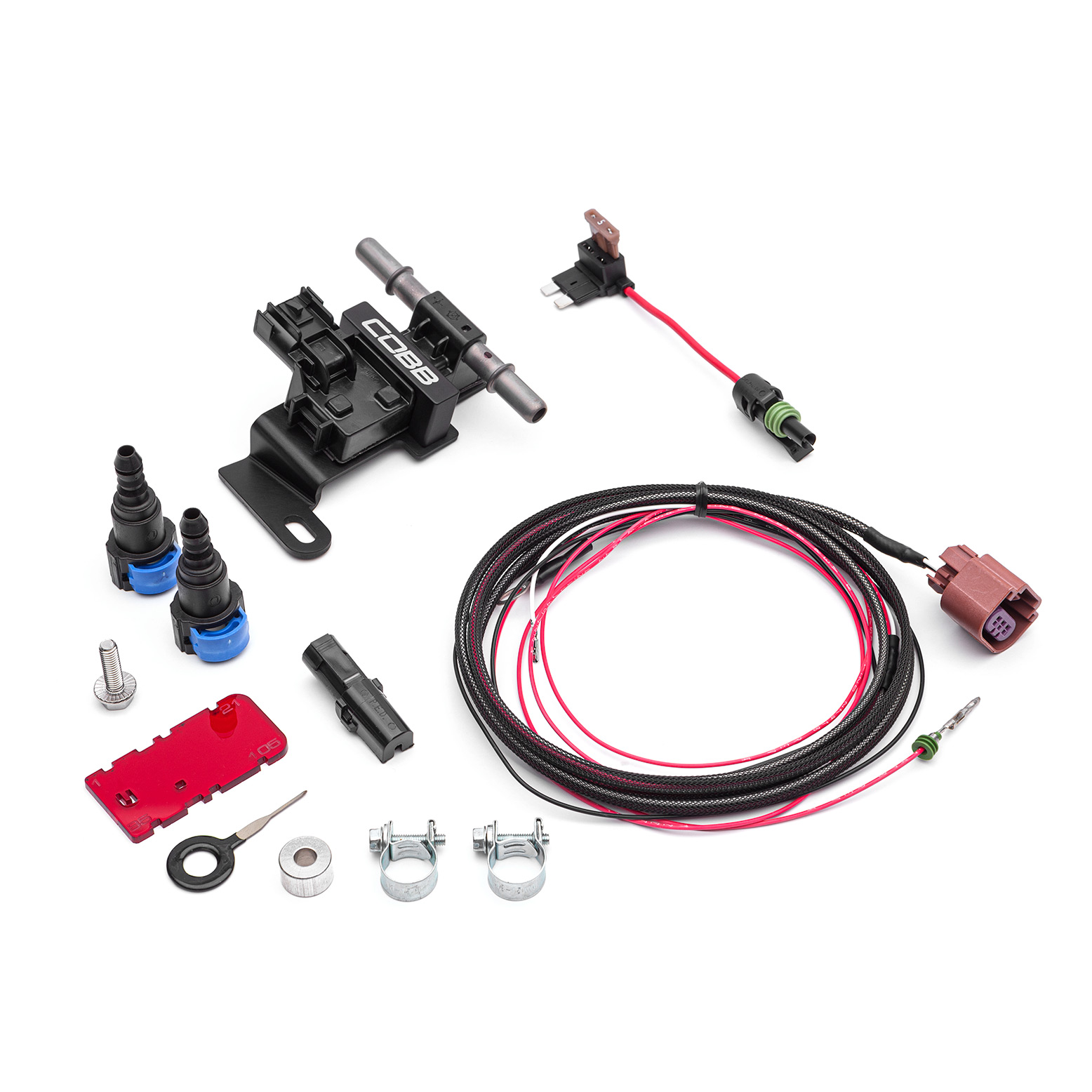
Parts List

Tools Needed
Sockets
3/8"
Hand Tools
- Phillips head screwdriver
- Flathead screwdriver
- Trim removal tool
Razor Blade or other safe cutting device
Vehicle Disassembly
- Park your car in a flat level area and allow it to completely cool down.
- Start the car and allow it to idle.
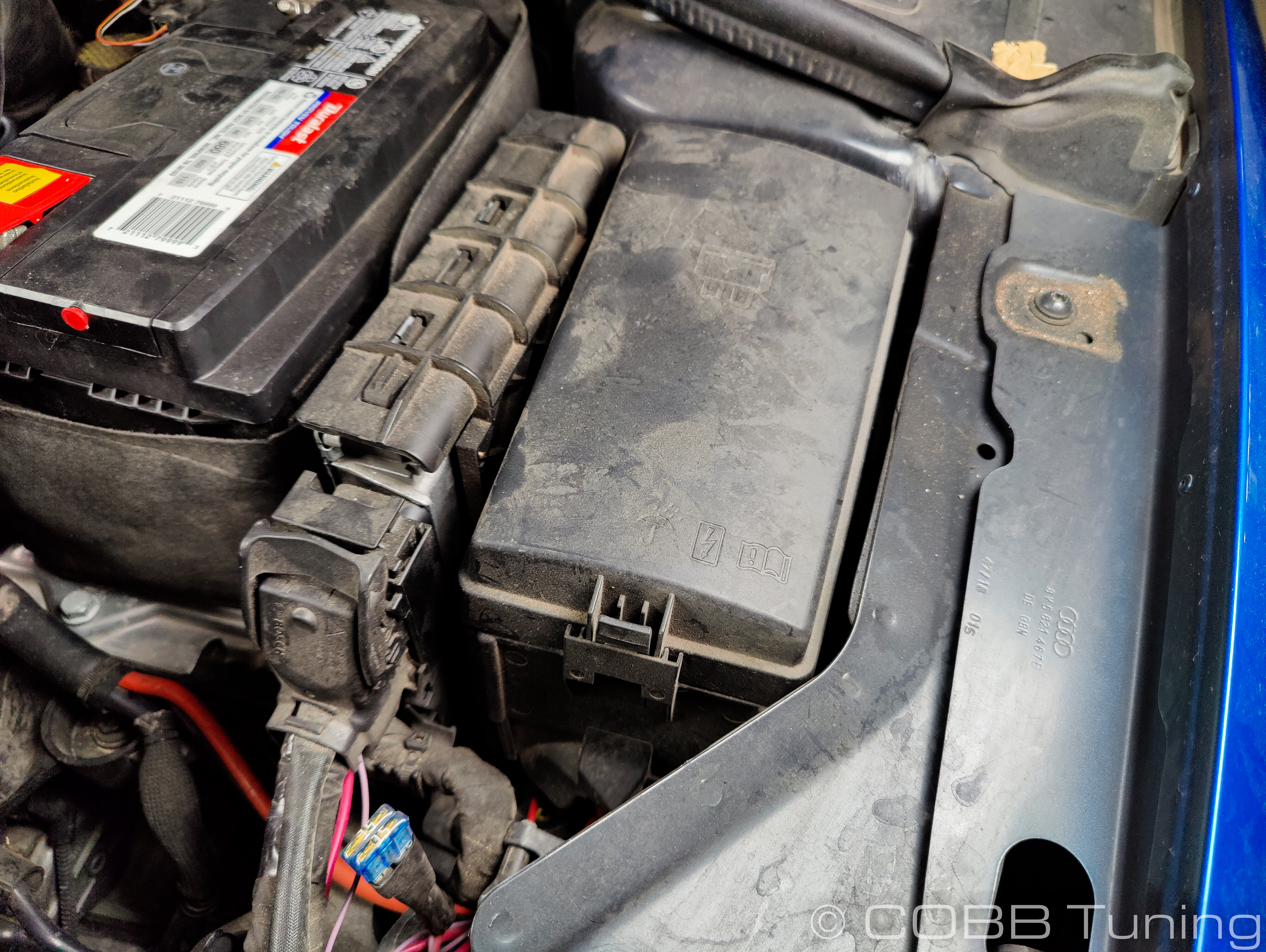
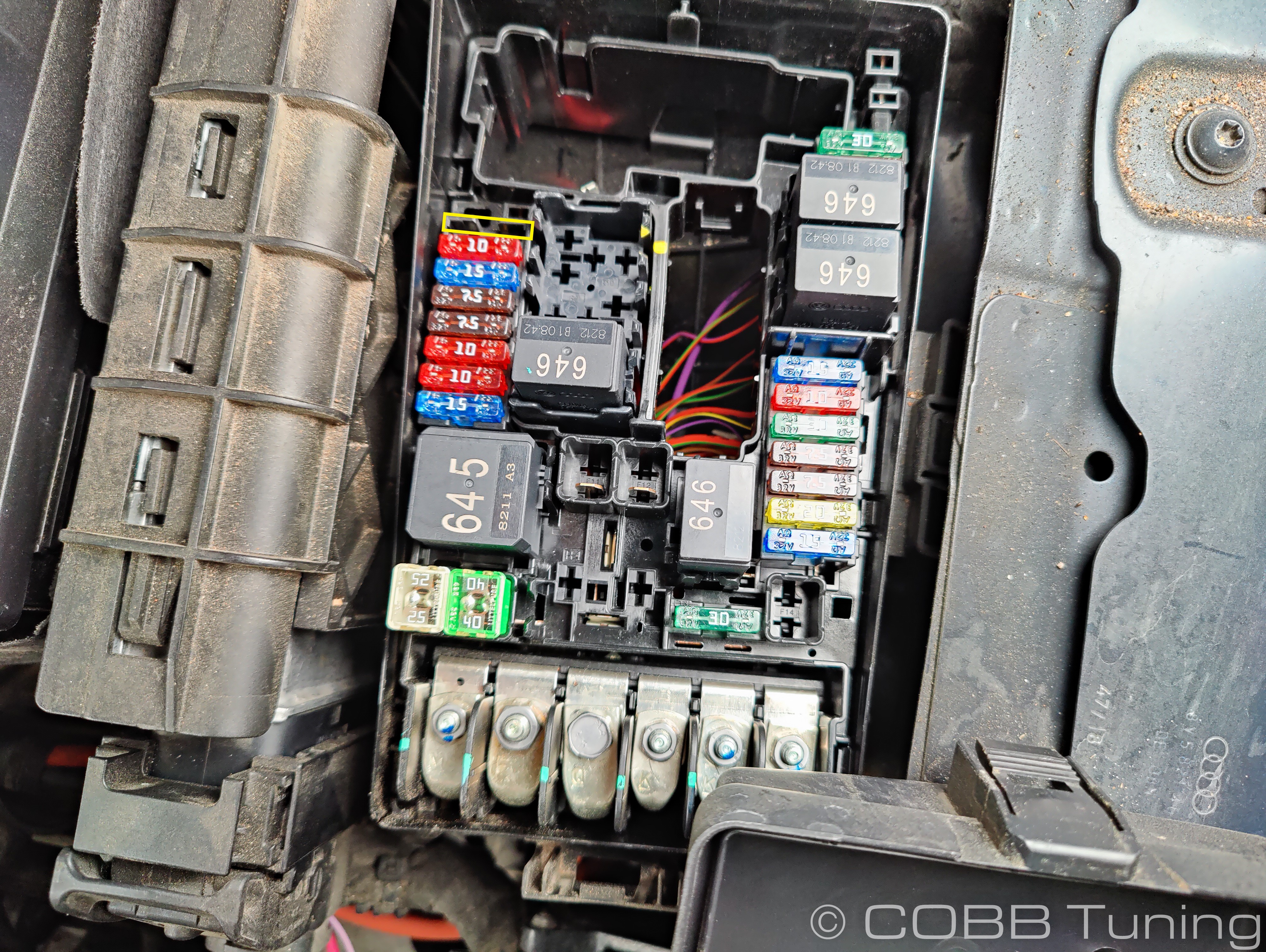
- Remove the fuel pump fuse (#10 in the under-hood fuse box on most cars, consult your owners manual)
- The car should stumble and die. This should minimize the fuel pressure in the system.
- Turn off the car
- Unhook the battery's negative terminal using a 10mm wrench.
- Remove the battery's positive terminal using the same 10mm
- Remove the battery by unbolting the bracket at the base using a 13mm socket and sliding the battery forward and out of the car.
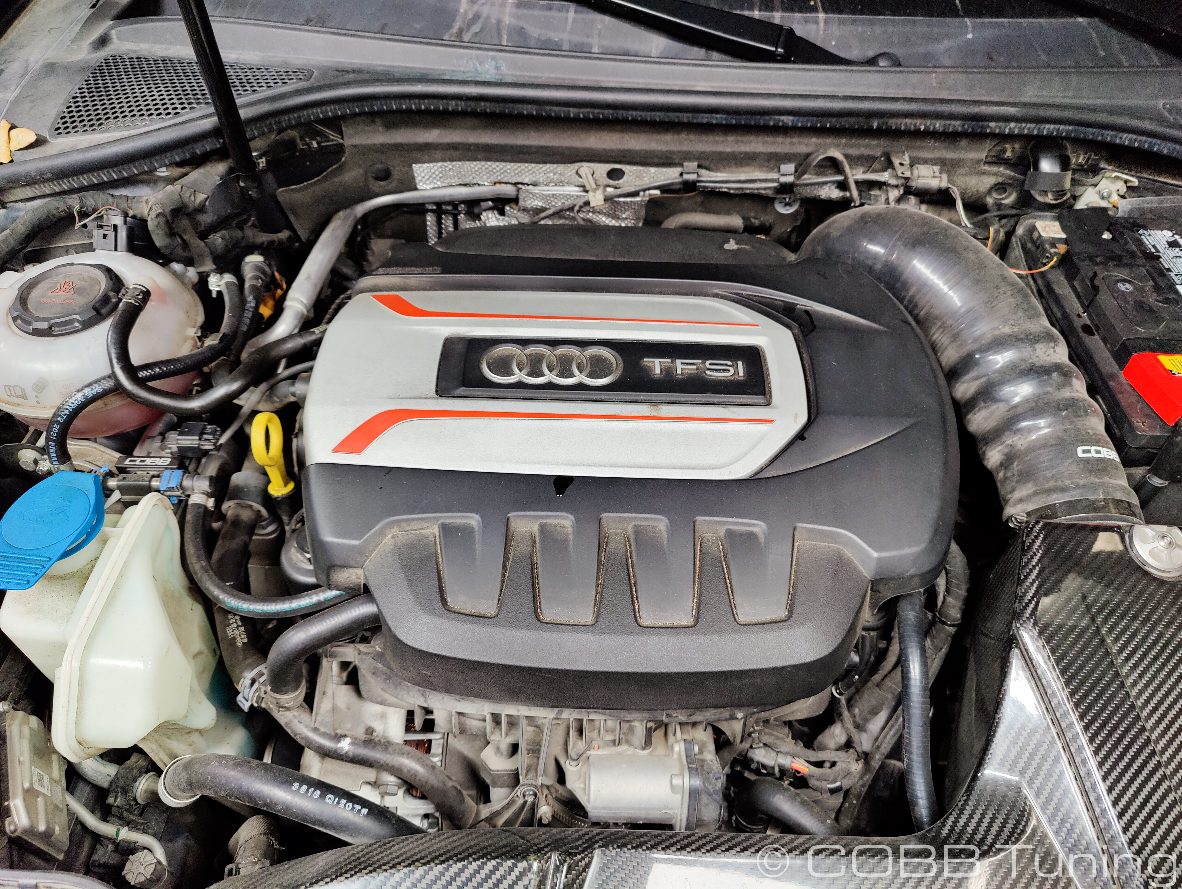
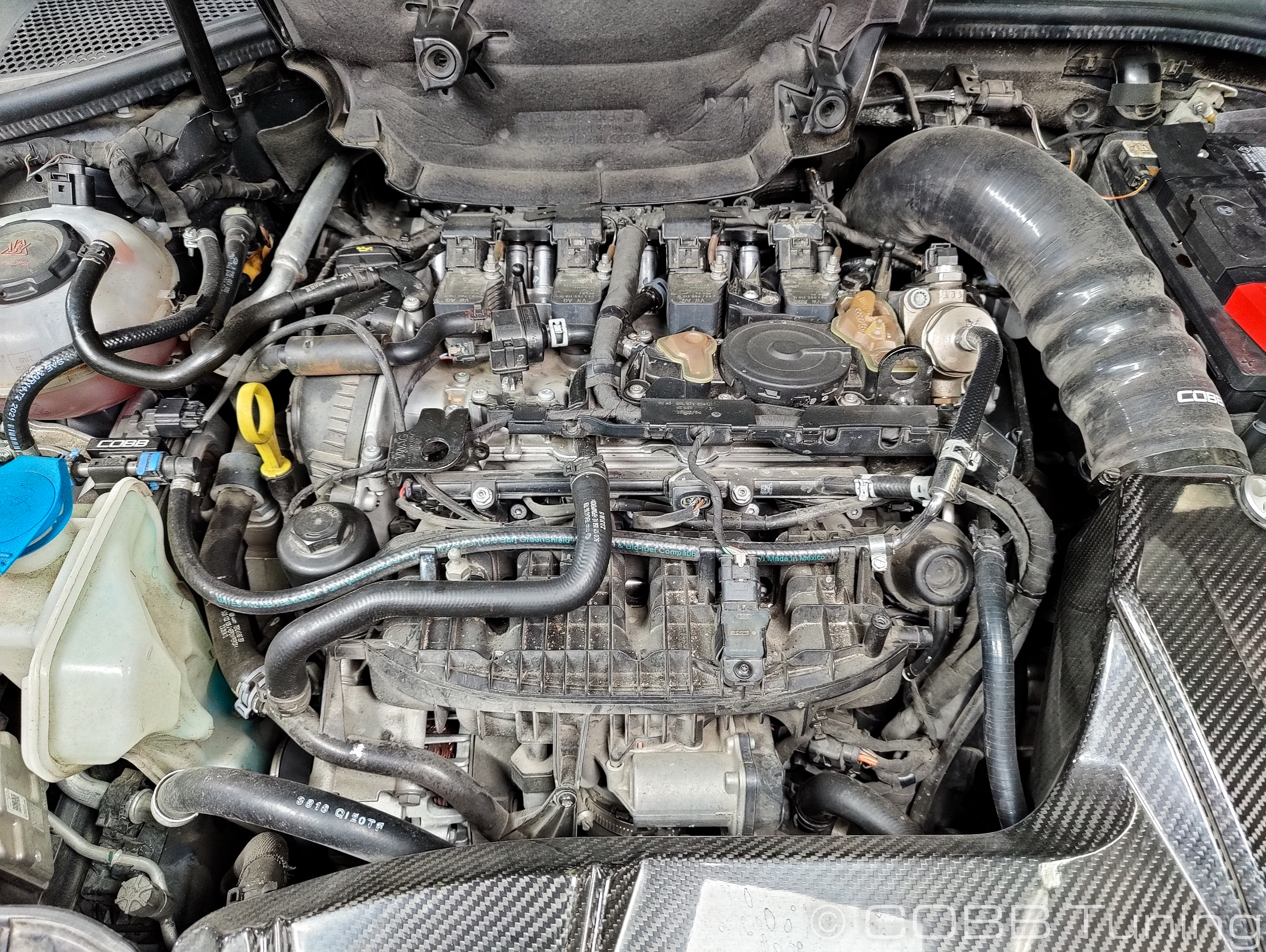
- Gently lift upward on the engine cover to take it off of the engine.
Flex Fuel Sensor Installation
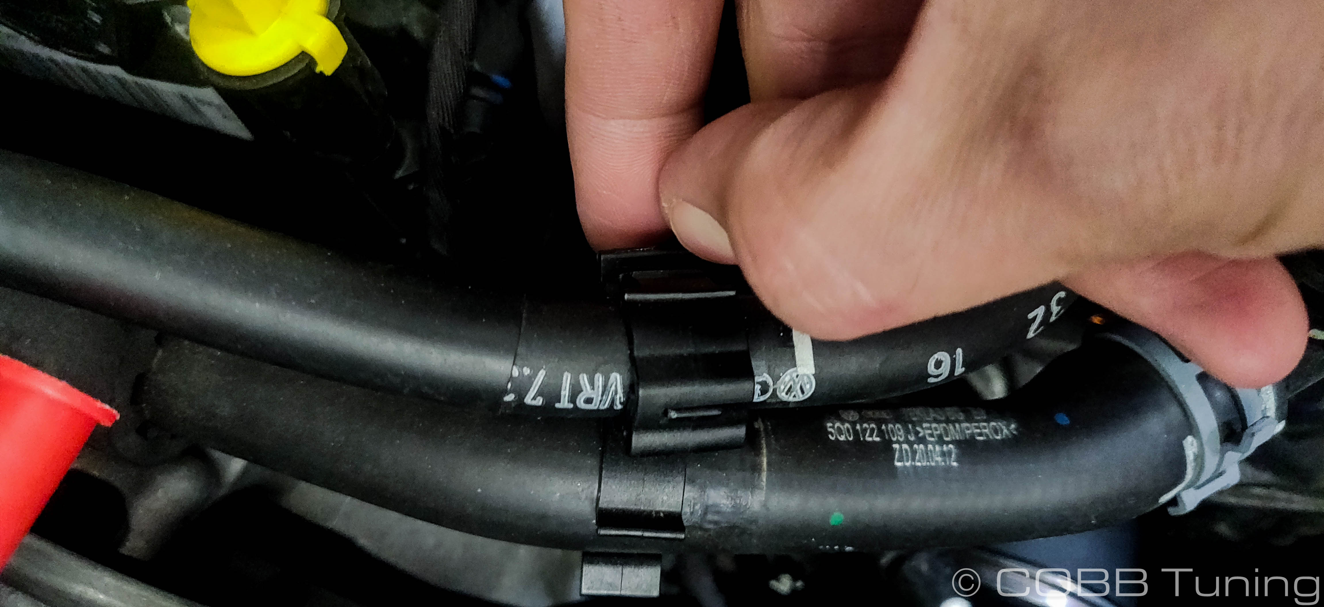
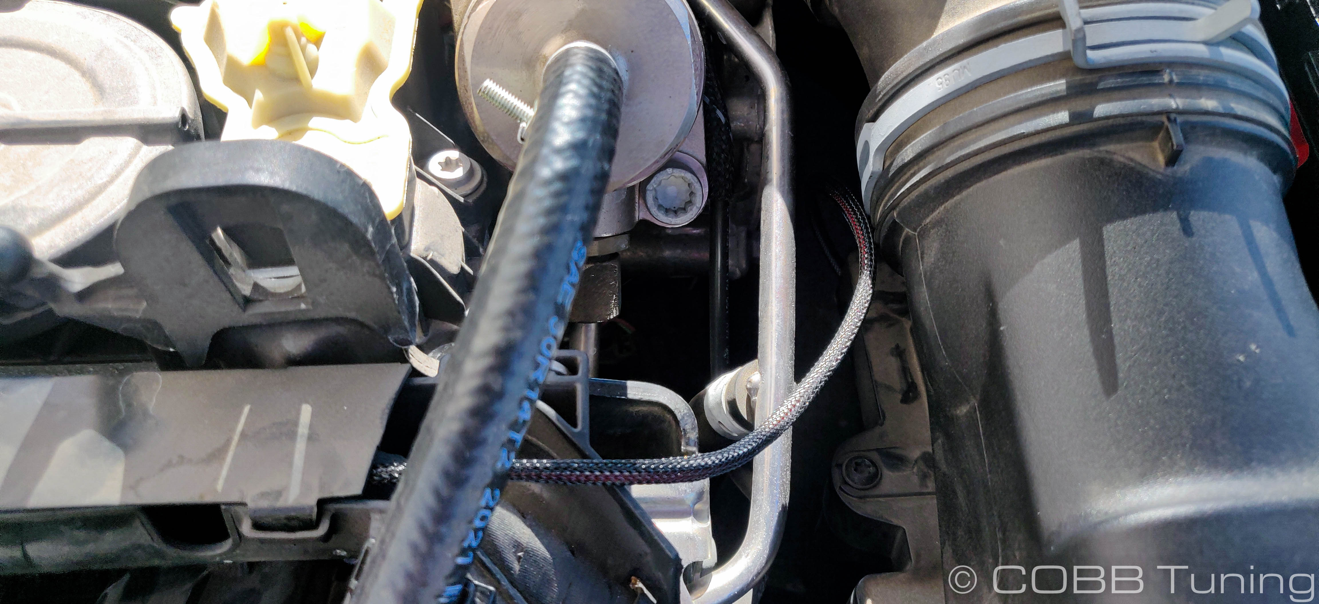
- Lift gently upwards to disconnect the plastic tie down for the fuel line.
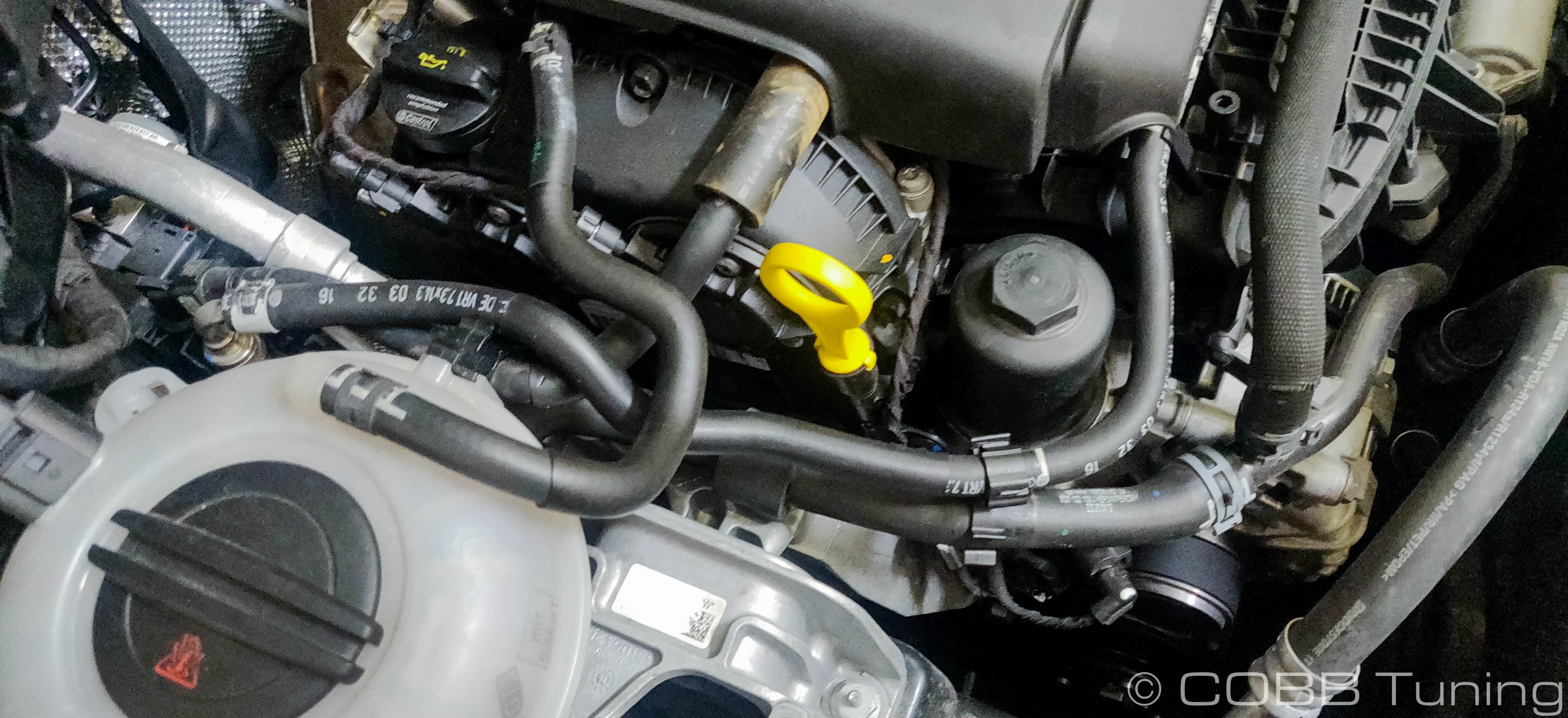
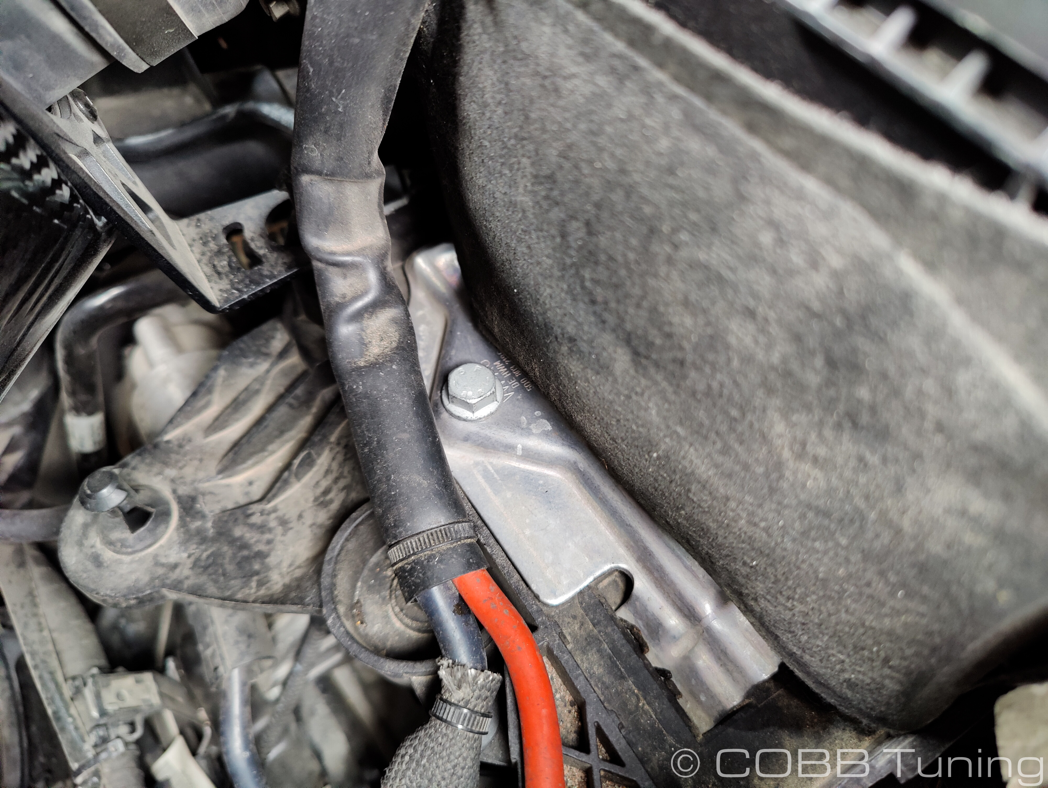
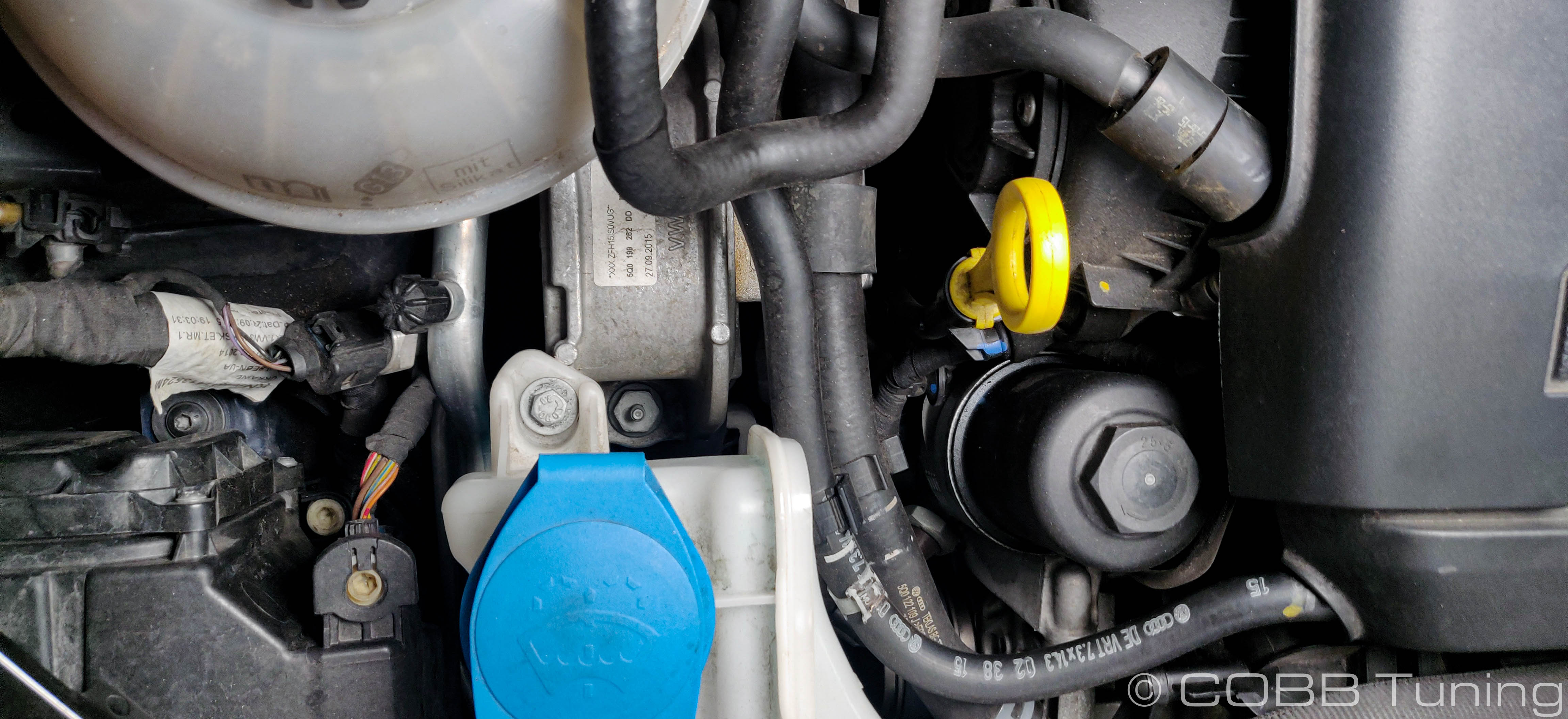
- Locate your passenger's side (usdm) motor mount
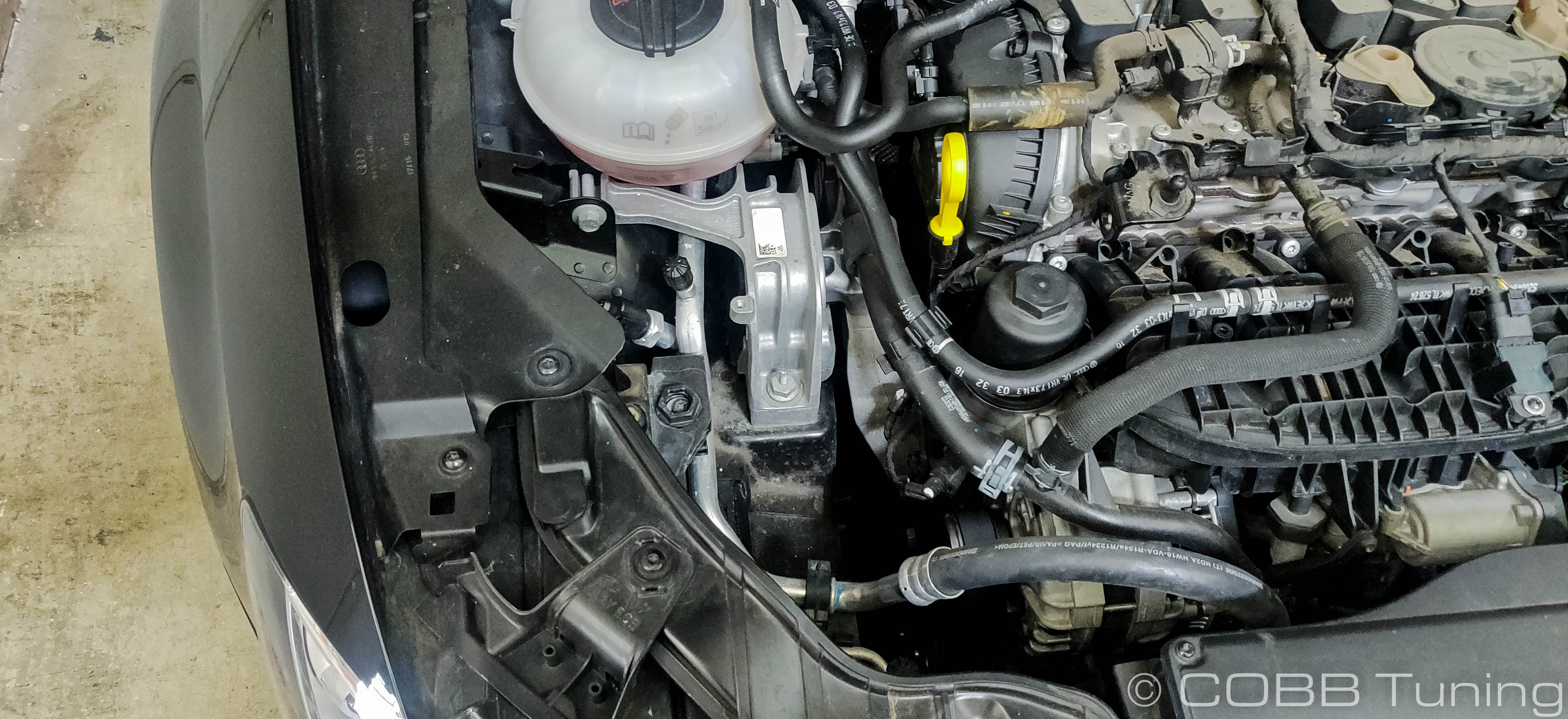
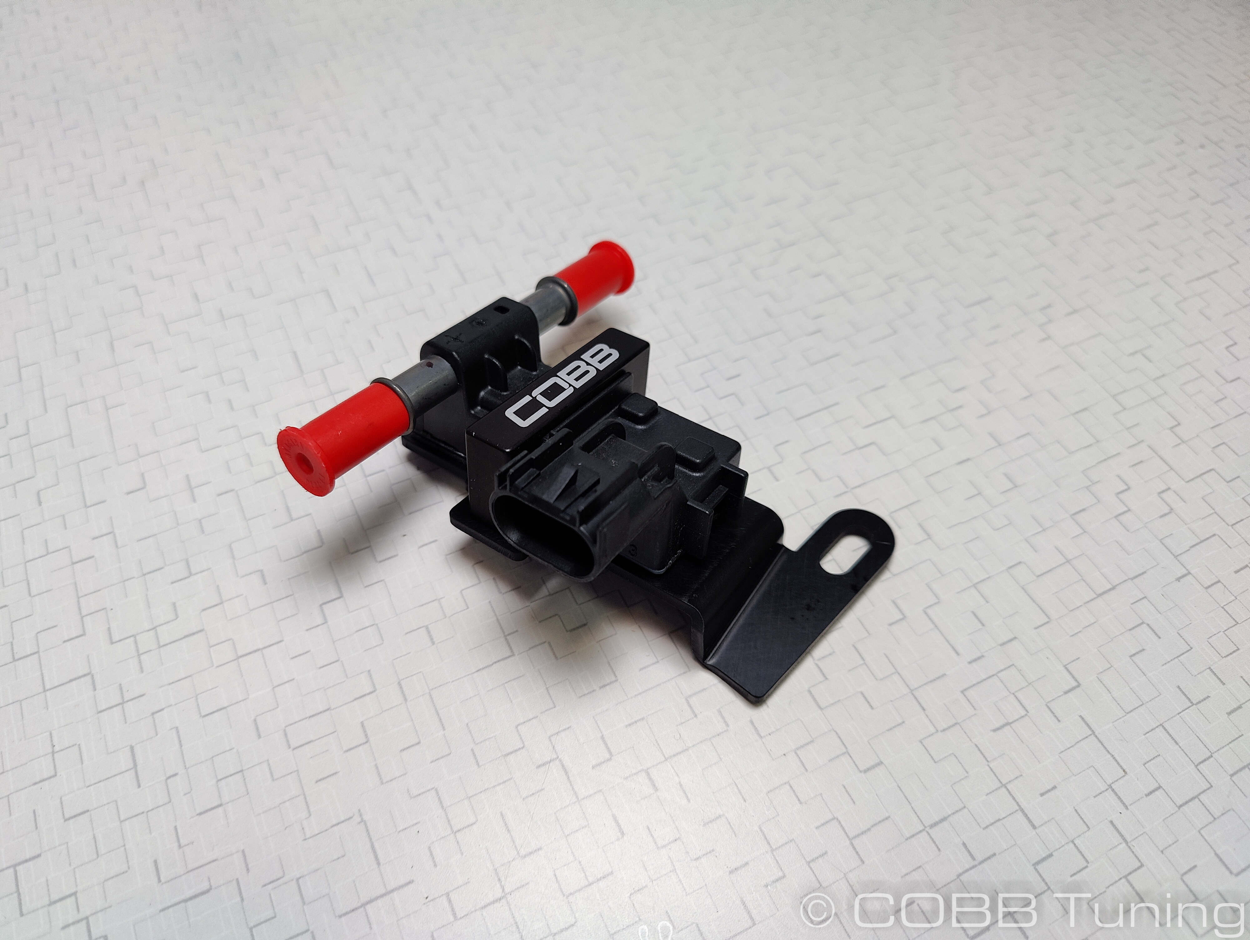
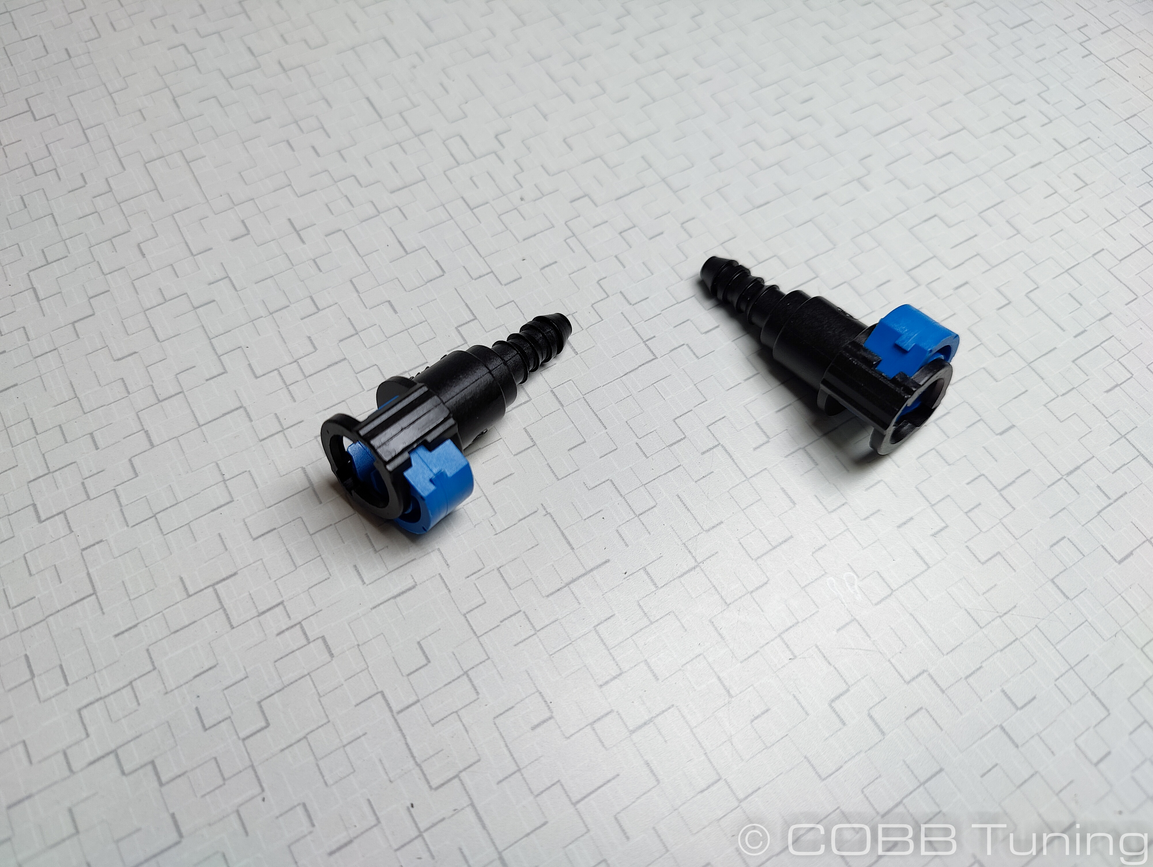
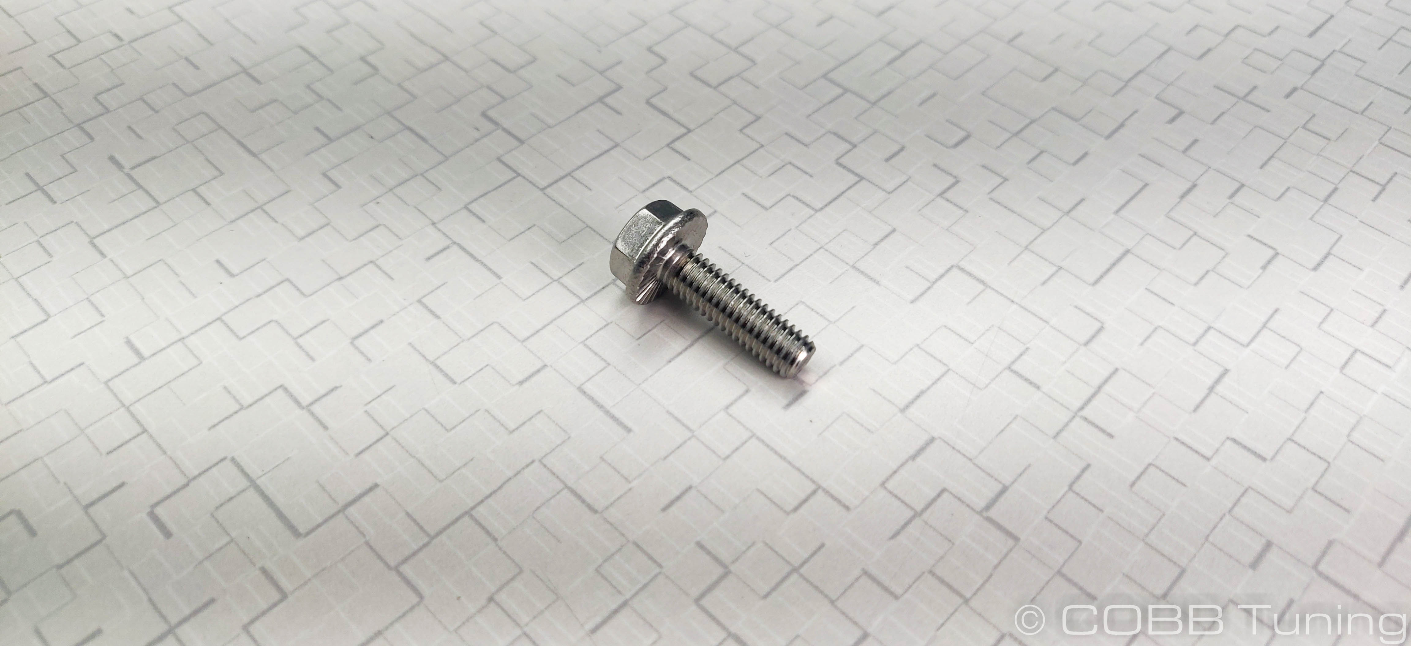
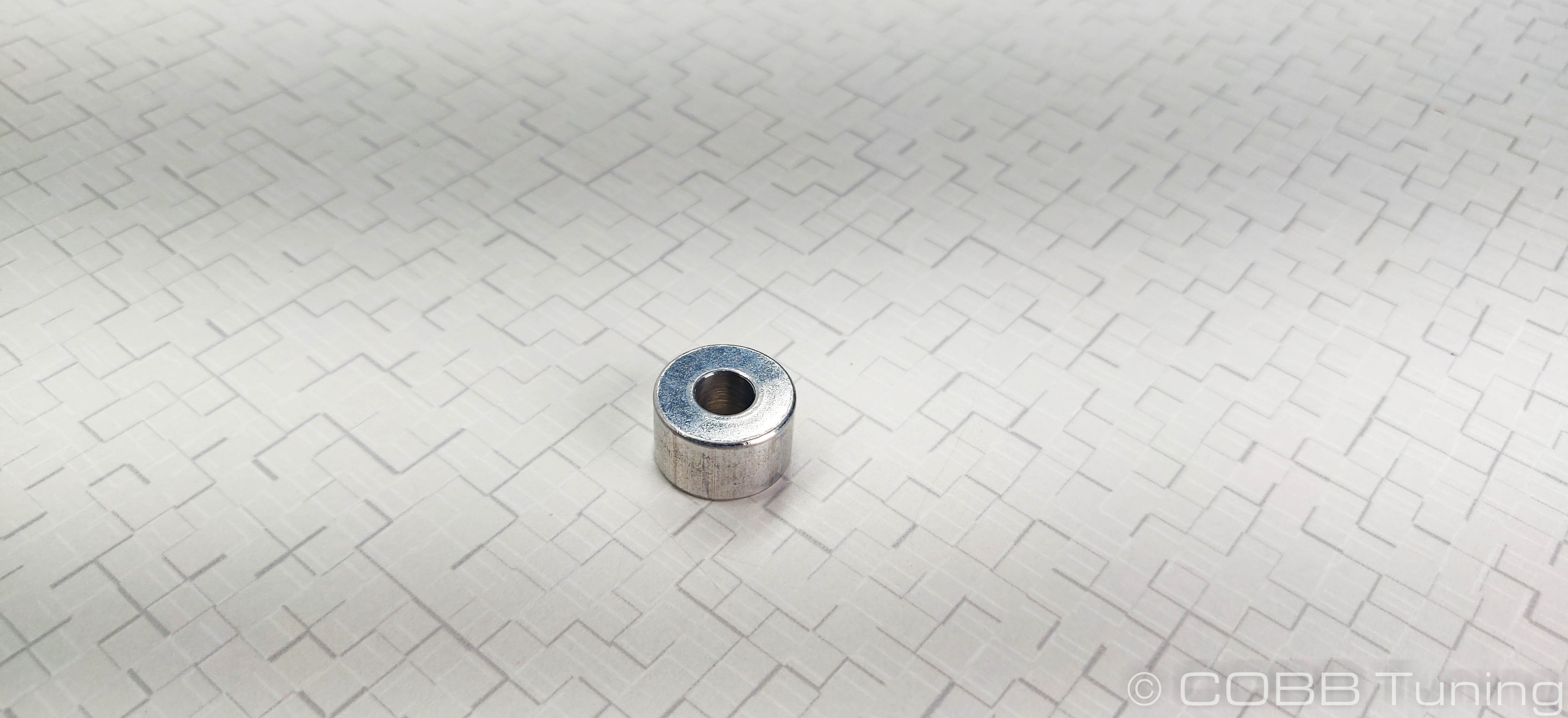
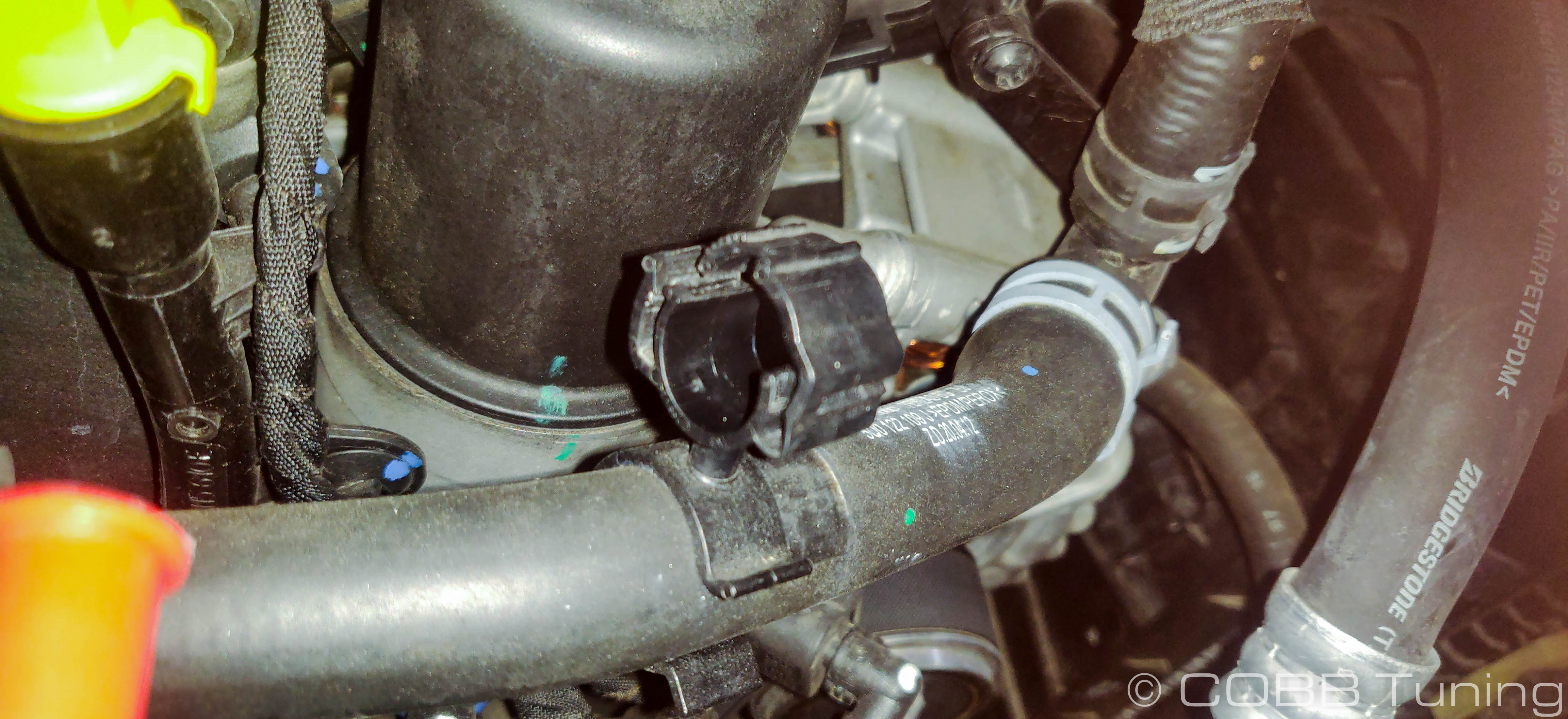
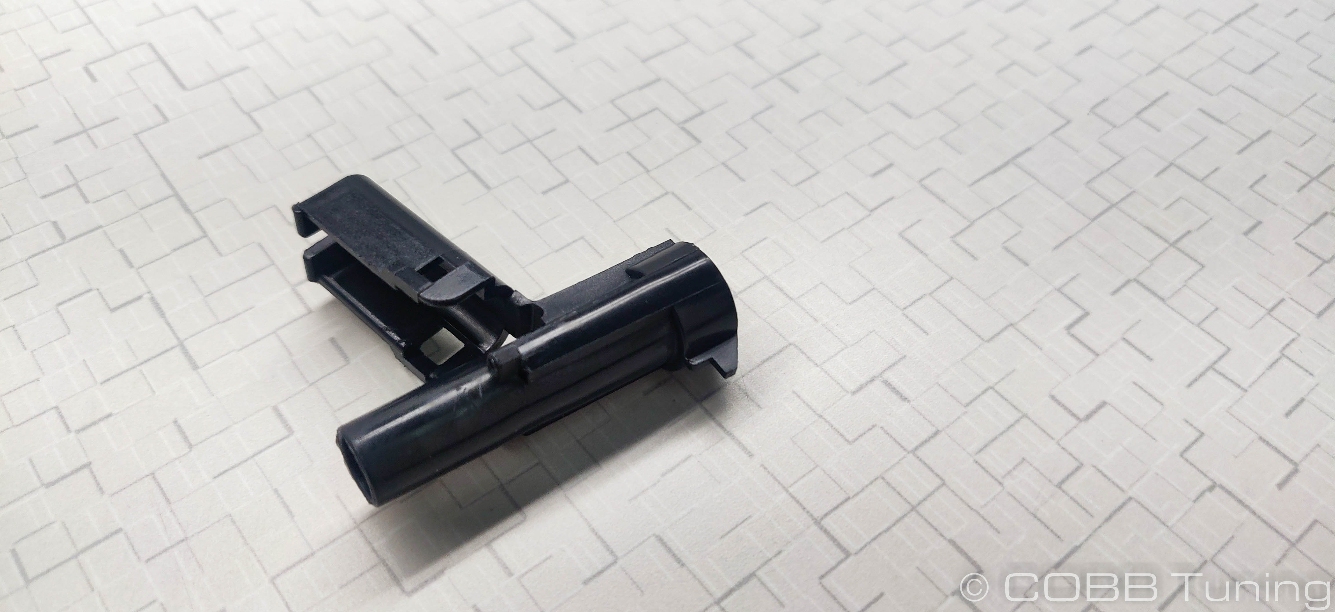
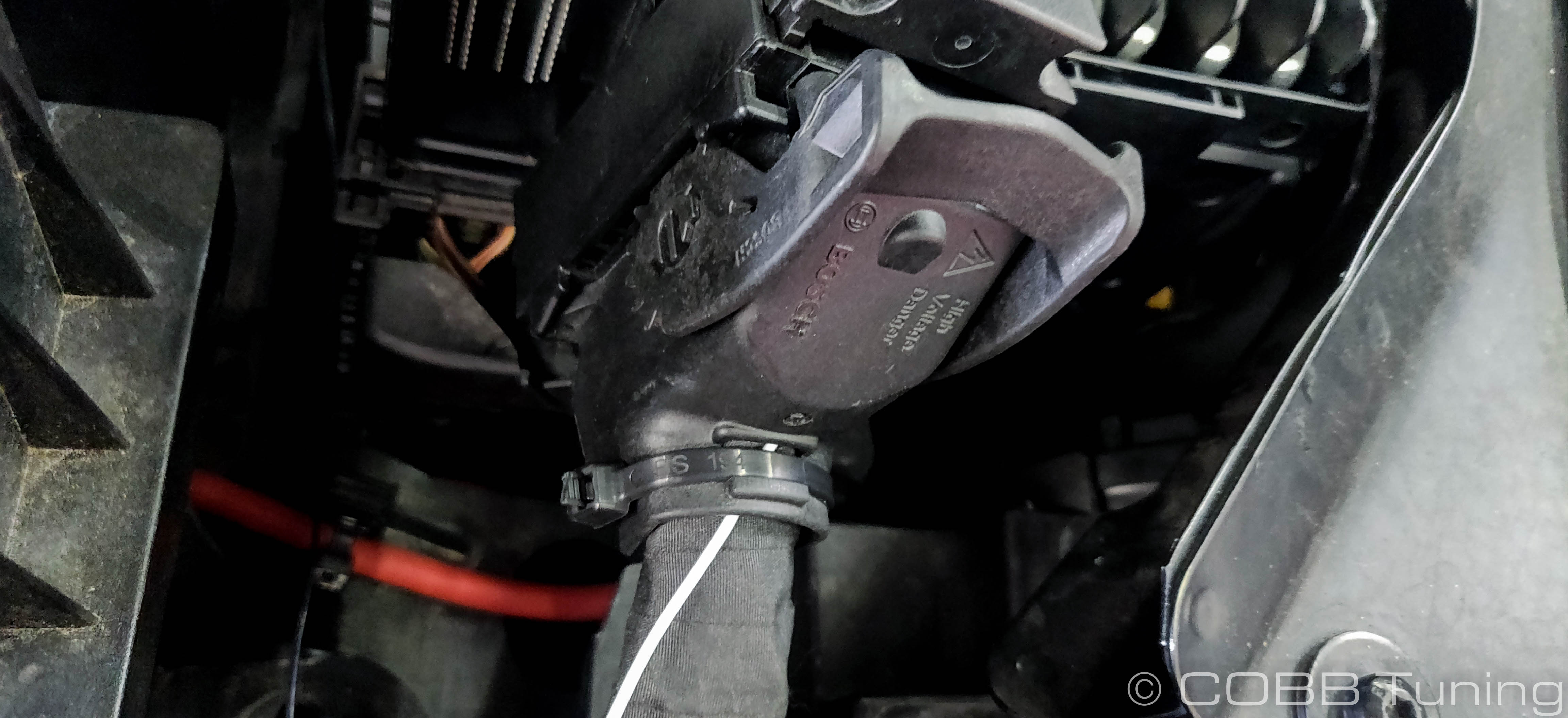
- Install the flex fuel sensor with the provided spacer and M6 bolt into the threaded boss on the side away from the engine. Slip the two quick connect fittings on to the sensor. Some vehicles have a tank that utilizes this hole but the spacer should push the assembly up high enough that it shouldn't be an issue.
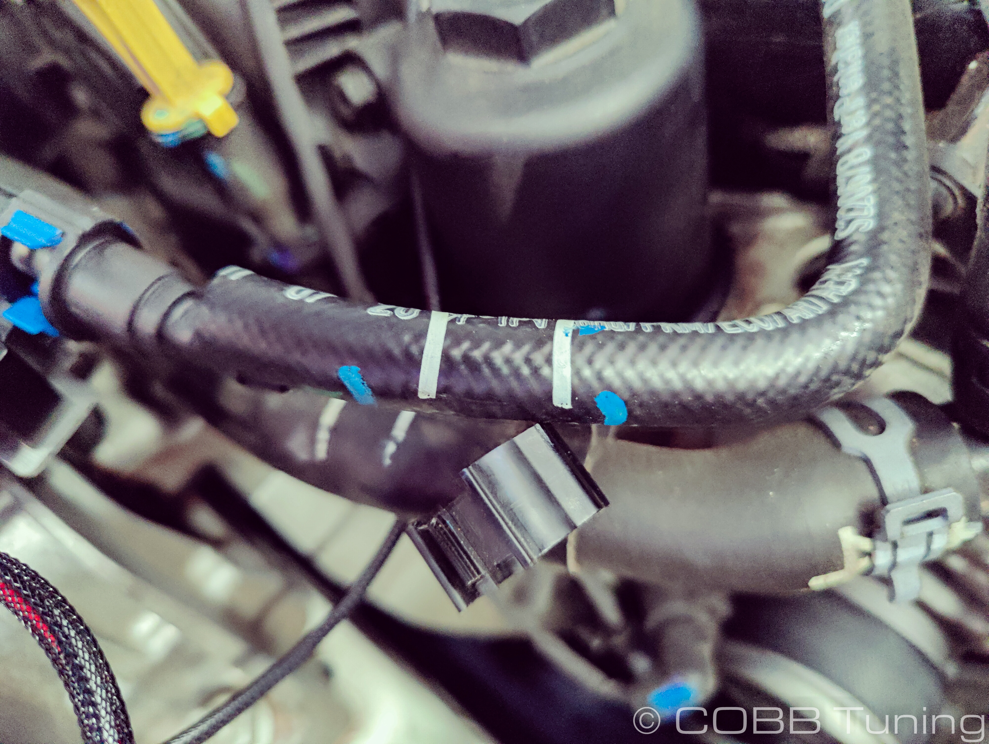
- Line up the factory fuel line close to/over the connectors and determine where to cut. We'll be cutting a small section out where the sensor would otherwise be in order to install it in-line with the fuel flow. You'll want to mark around where the fitting hits the widest part, but leave a little bit of extra line in place.
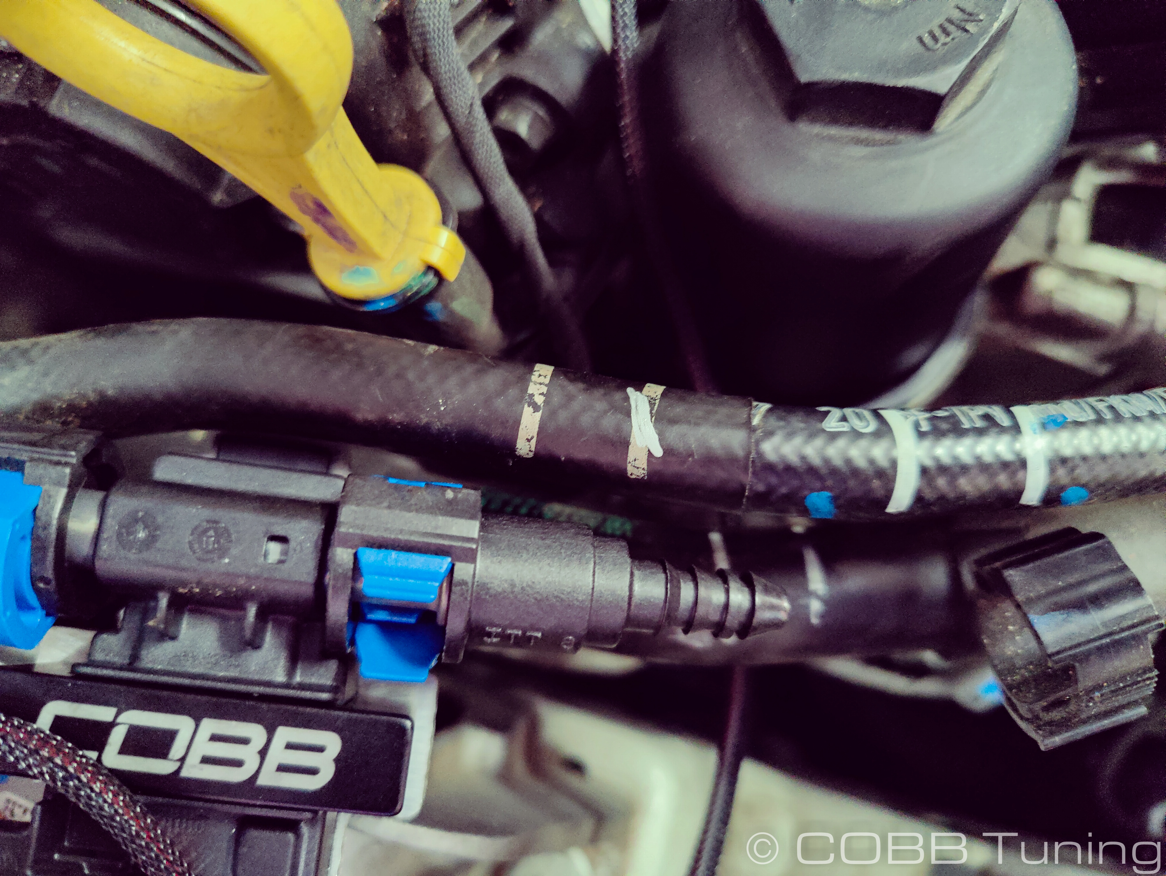
- Using a hose cutter or razor blade cut the stock hose on the drawn marks. You can't come back and add more line later so cut less than you think you need to! We also put a towel underneath the line to catch any fuel that will spill out.
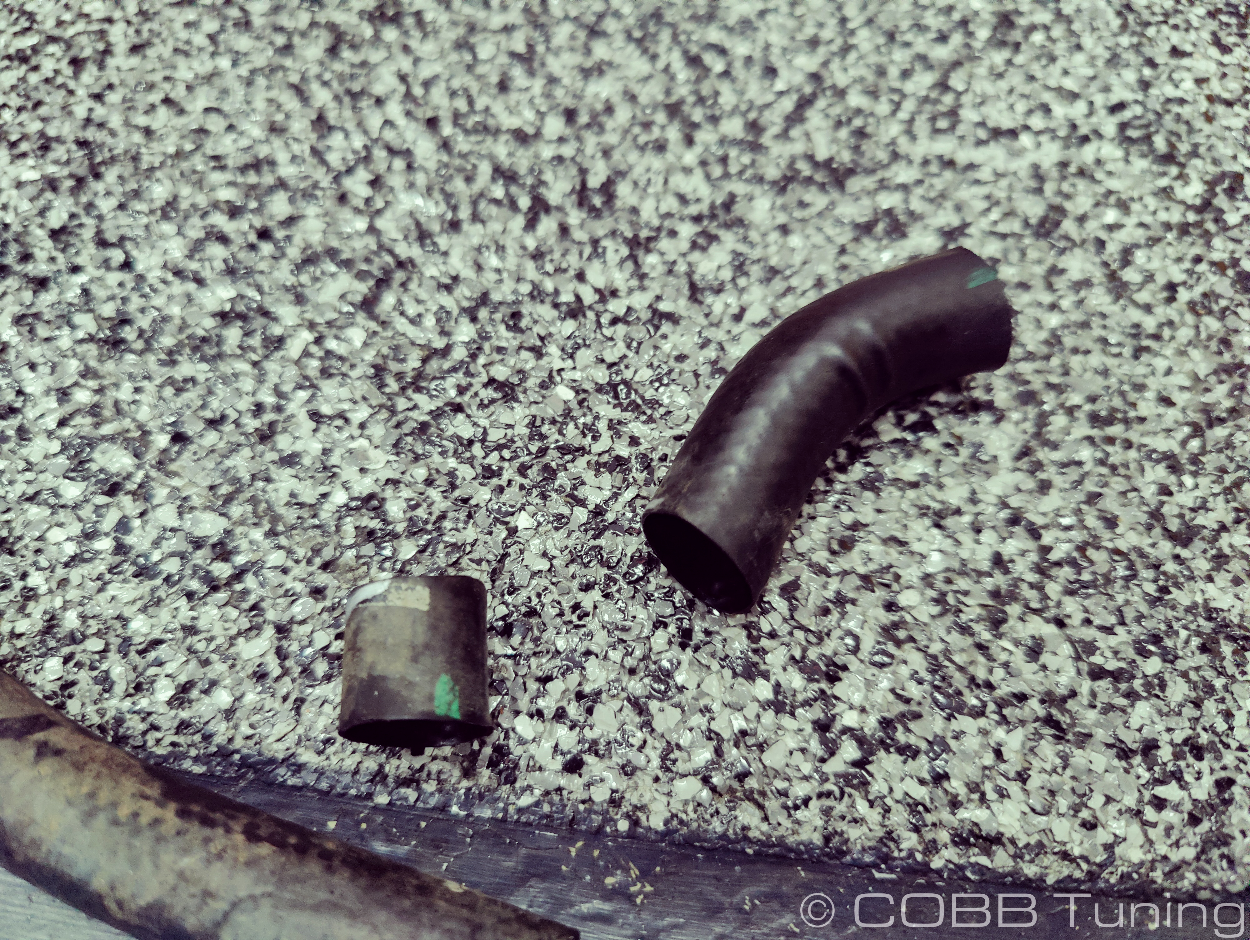
- Slip the anti chafing cover off the stock fuel line. It should slip off easily, if not you may need to carefully cut it off the hose without nicking the fuel line underneath.
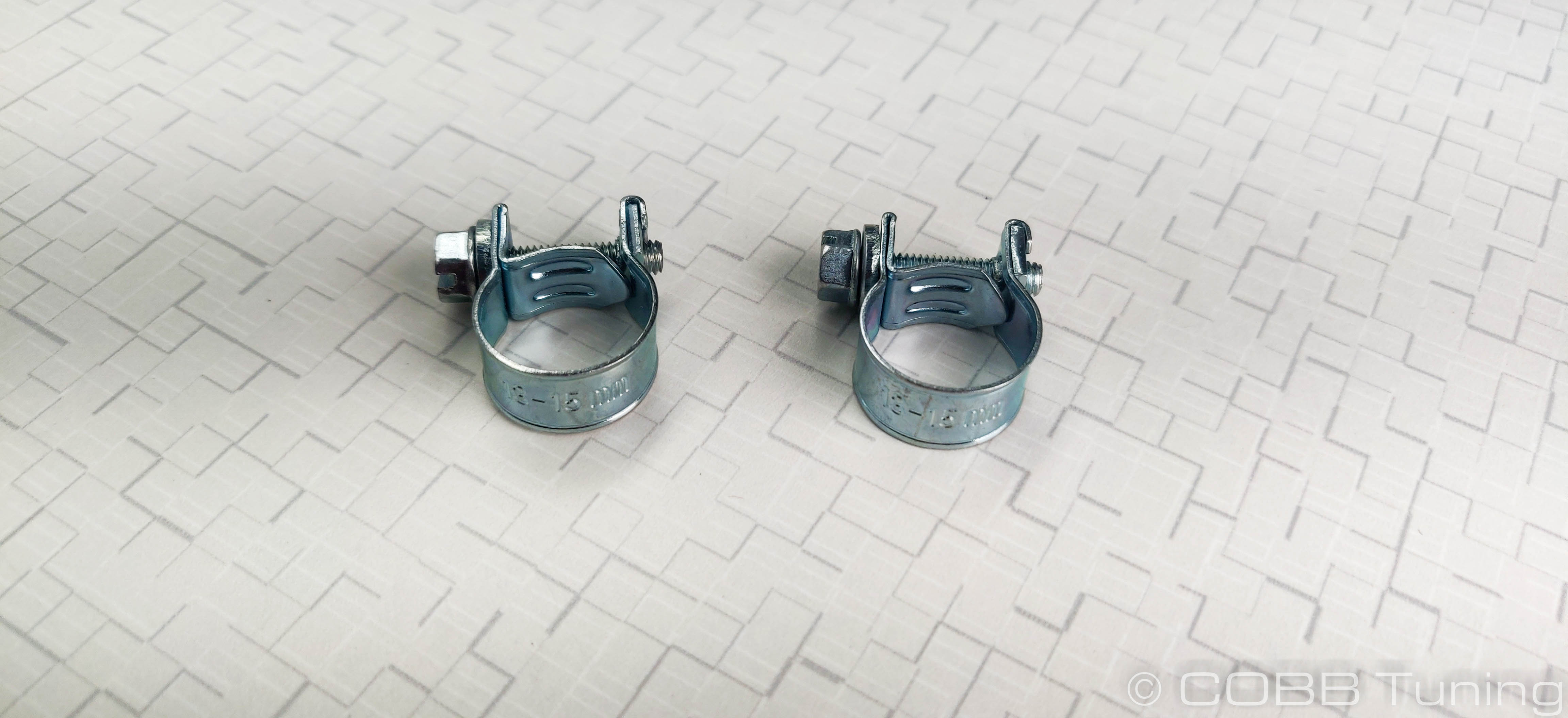
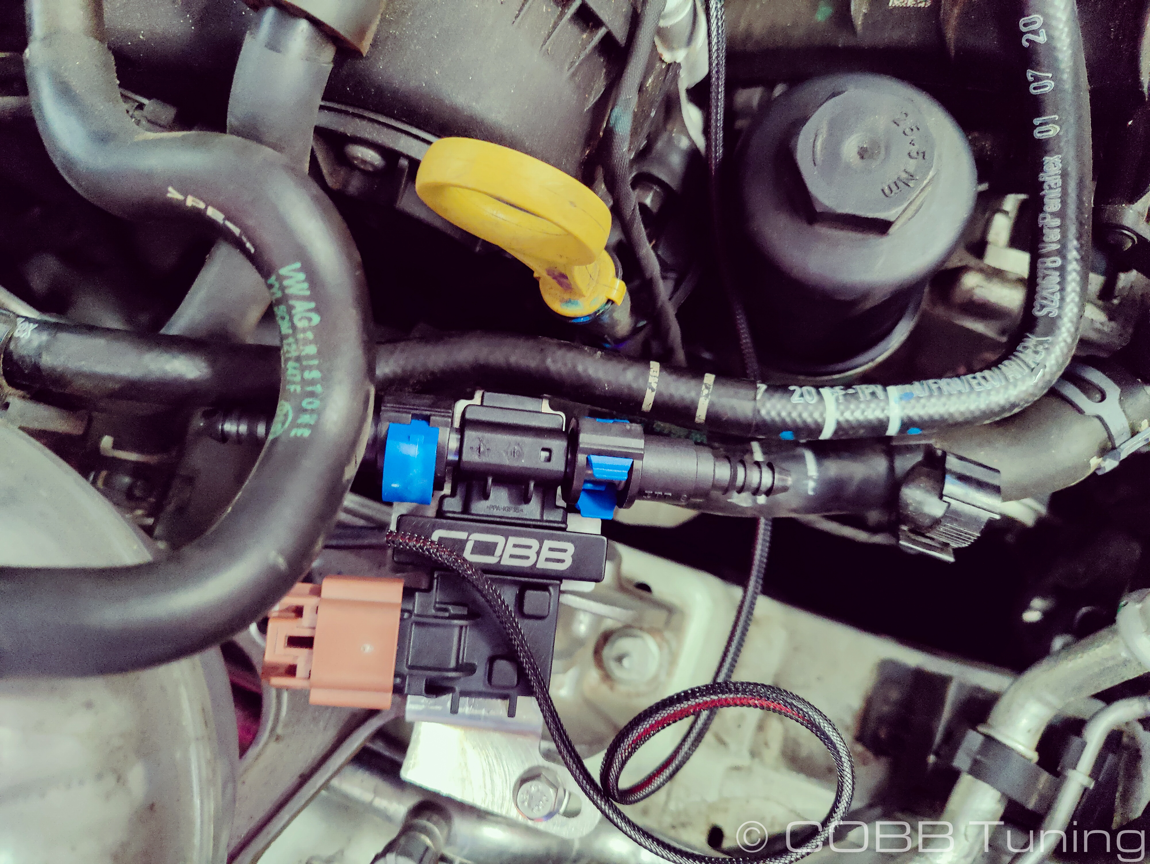
- Slide a hose clamp over the remaining fuel line lengths and then add a little silicone spray lubricant over the fittings before pushing them into the line. Secure them with the hose clamps.
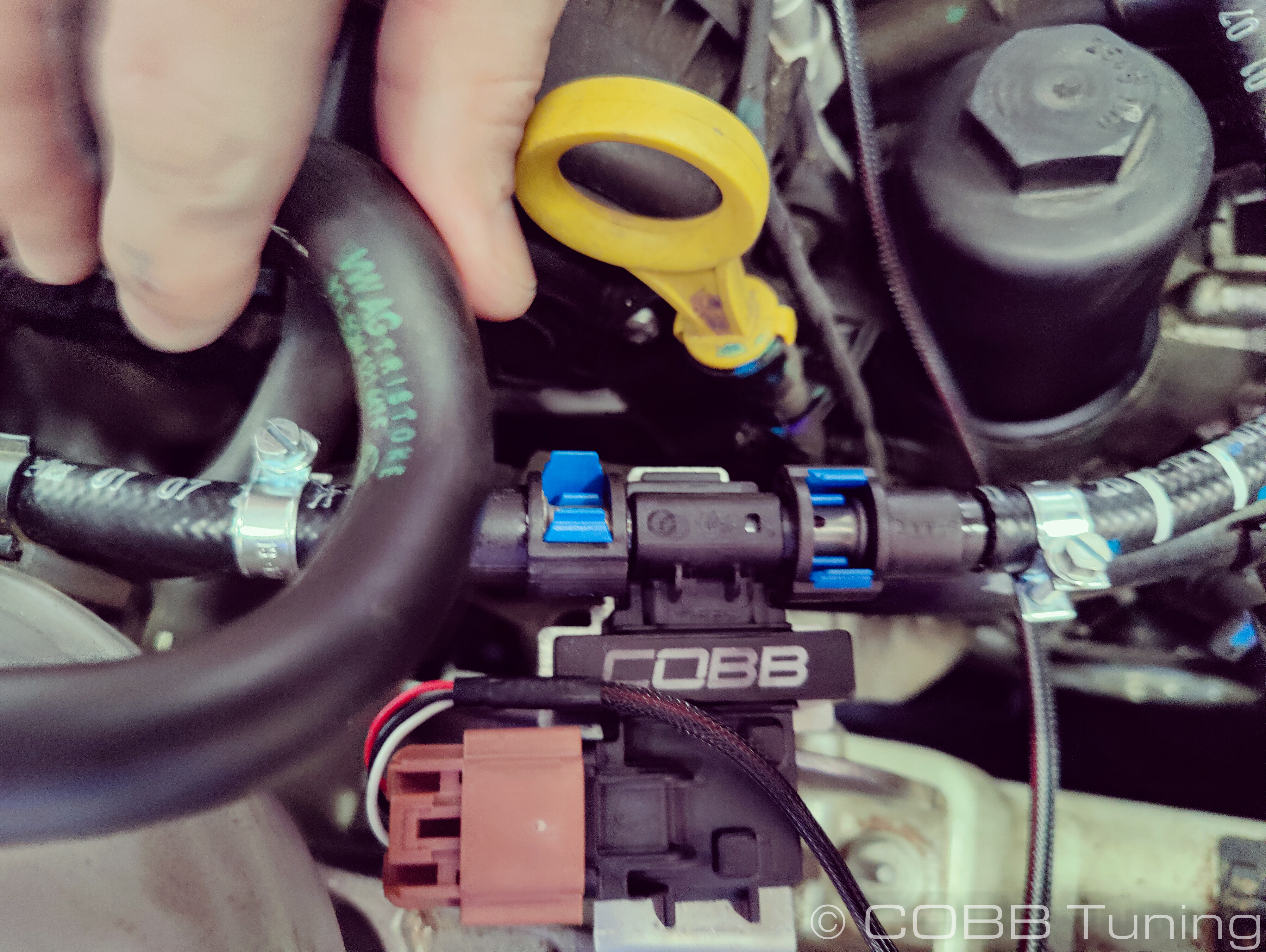
- The lines can then get connected to the sensor and have the connector locked in place. You can slip the fuel line back into the retention clip.
Wiring Harness Installation
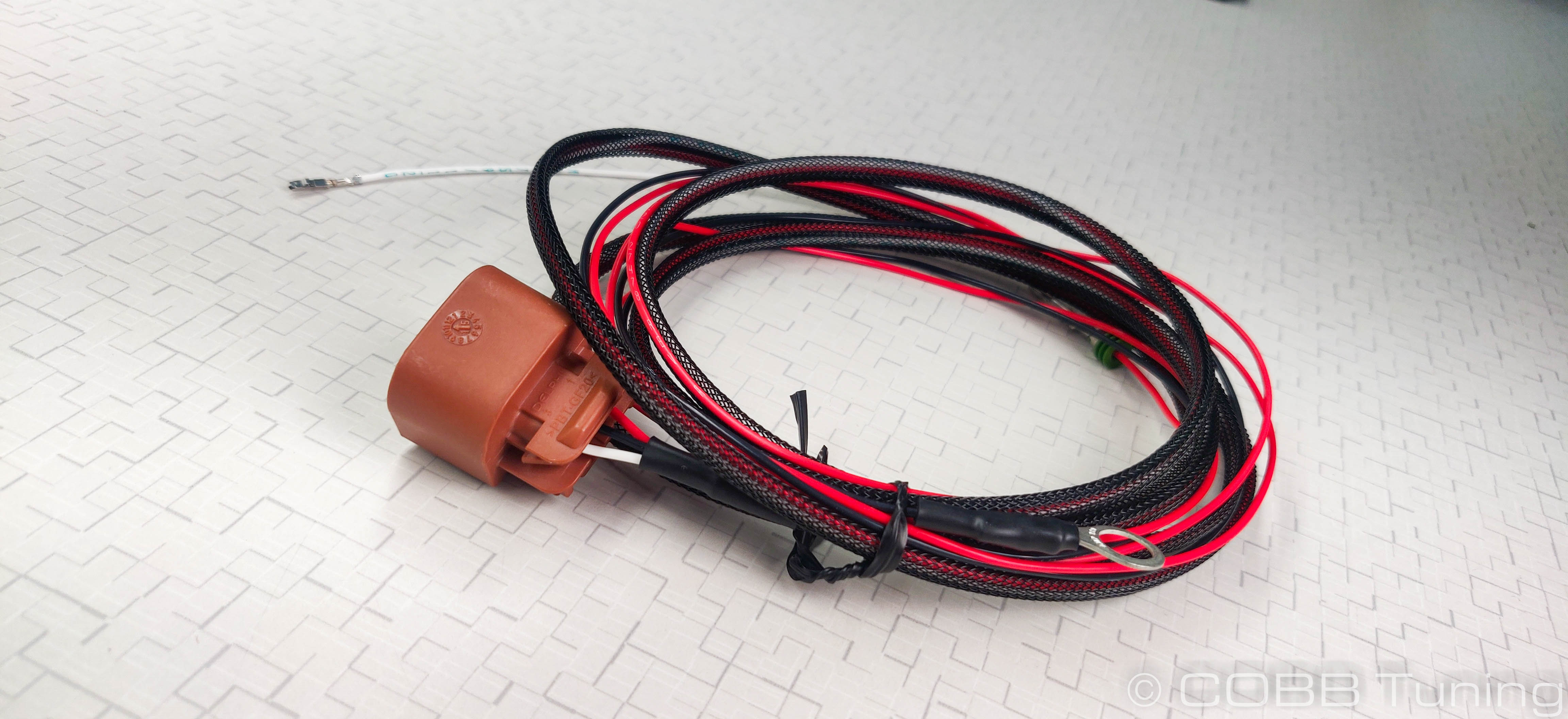
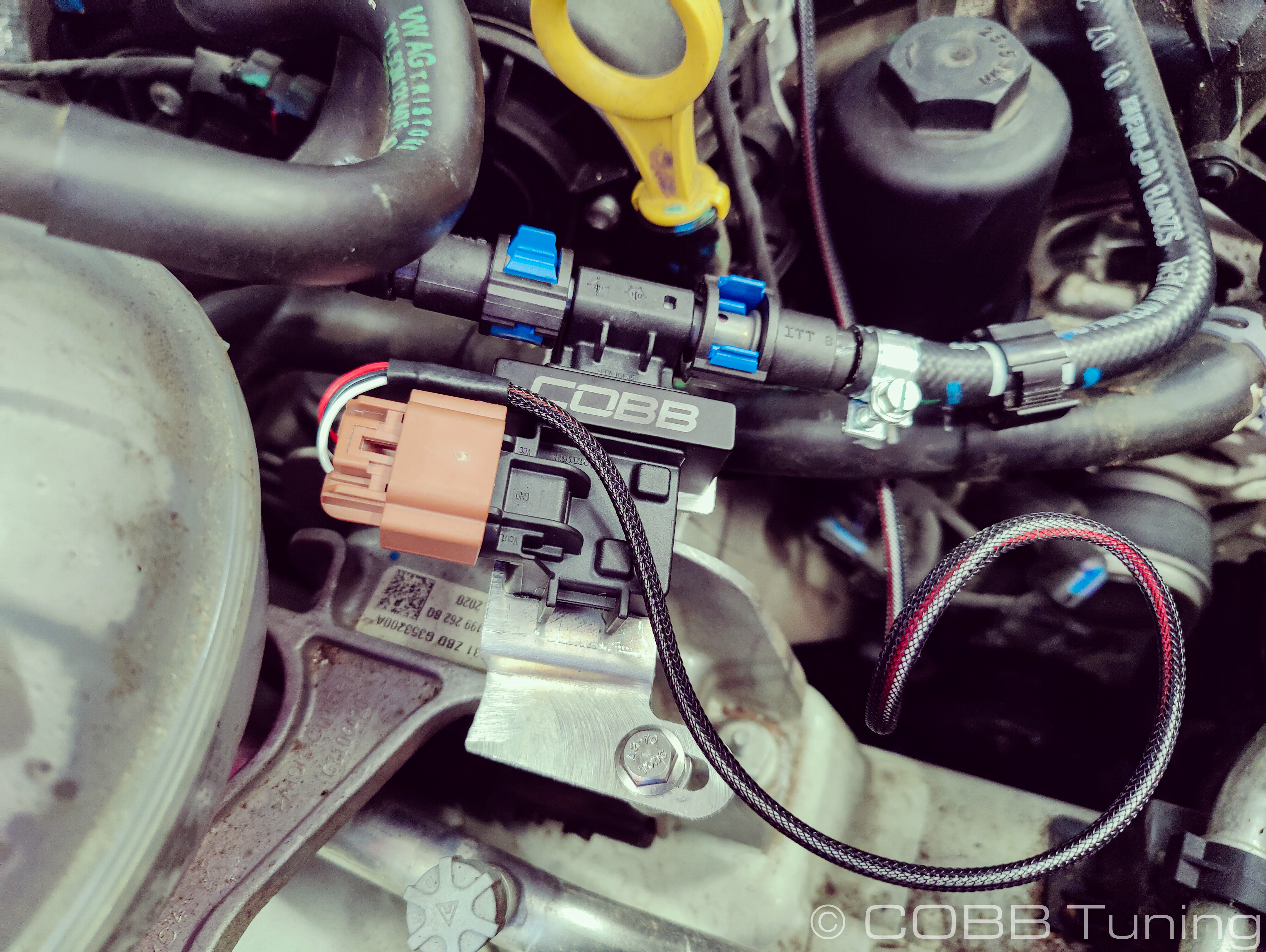
- Plug the provided wiring harness into the ethanol content sensor.
- Loosen the wiring tray above the front of the valvel cover using a small screwdriver to gently pop the tabs out.
- Route the wiring through the tray leaving a little bit of slack on the end with the sensor to allow for movement before closing the tabs.
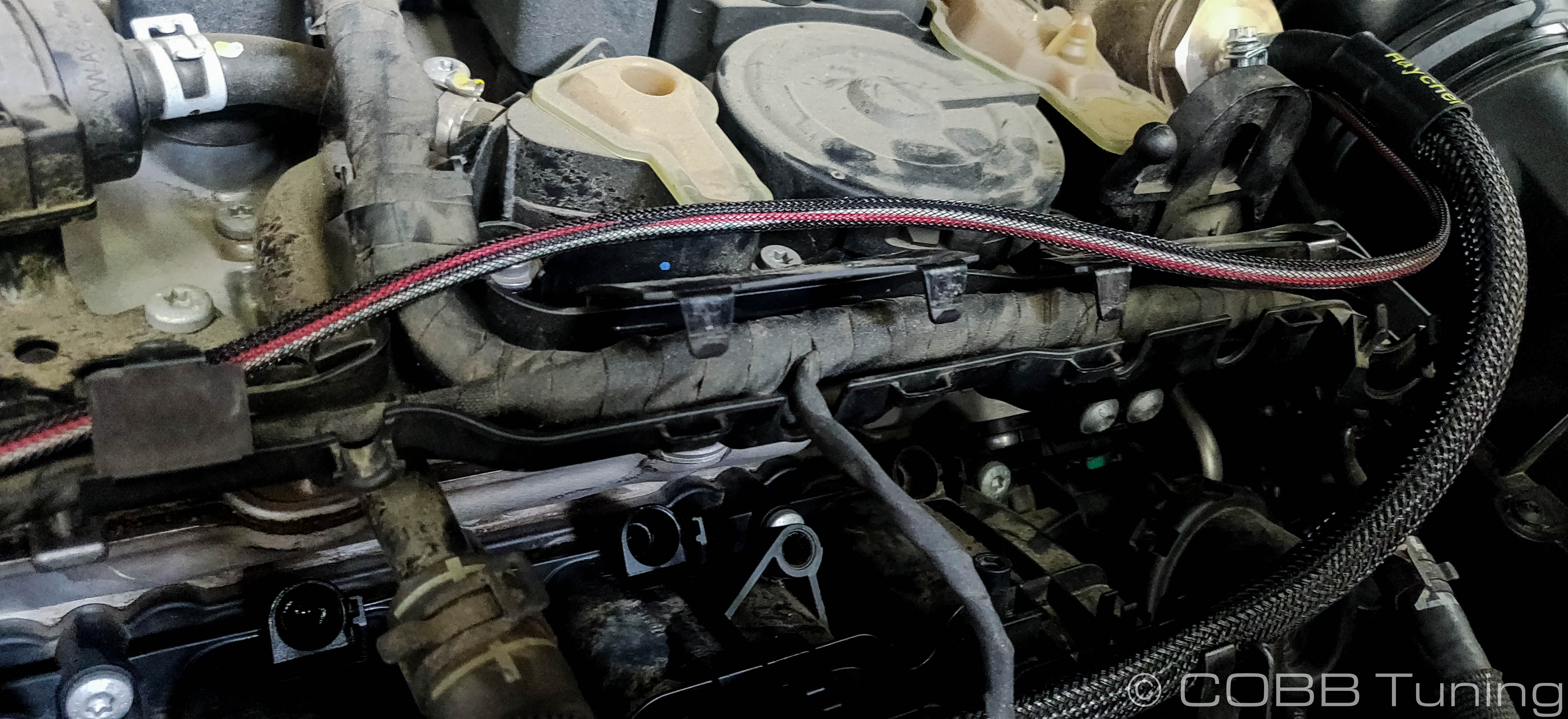
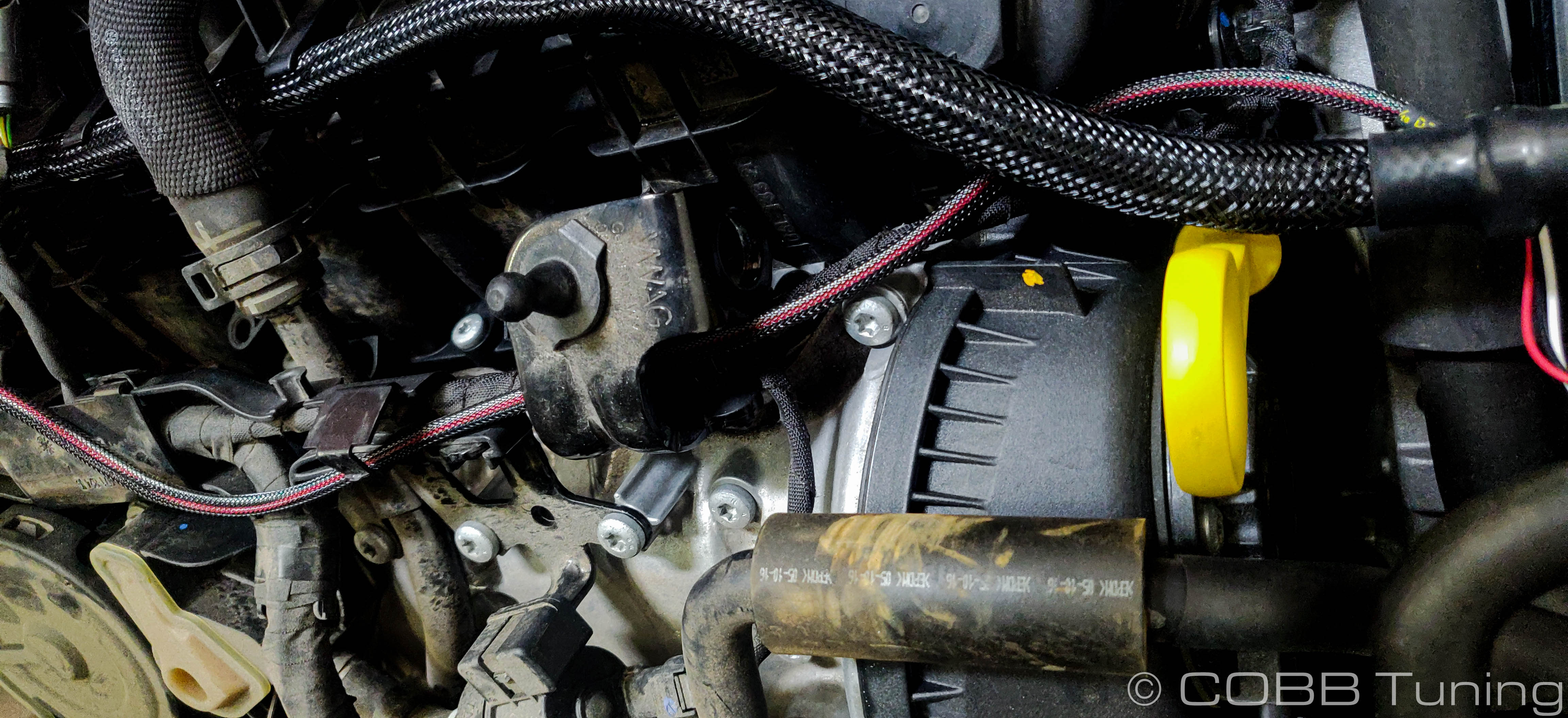
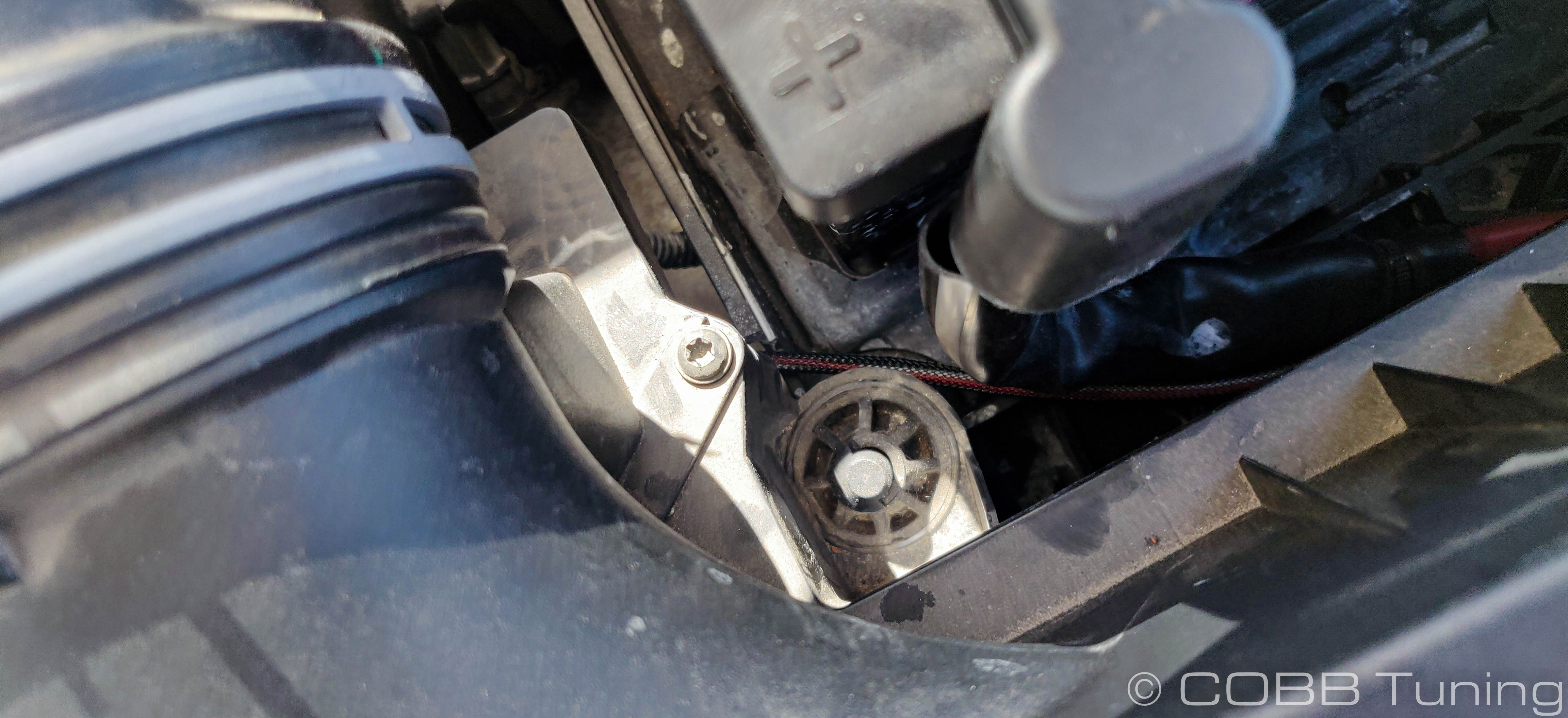
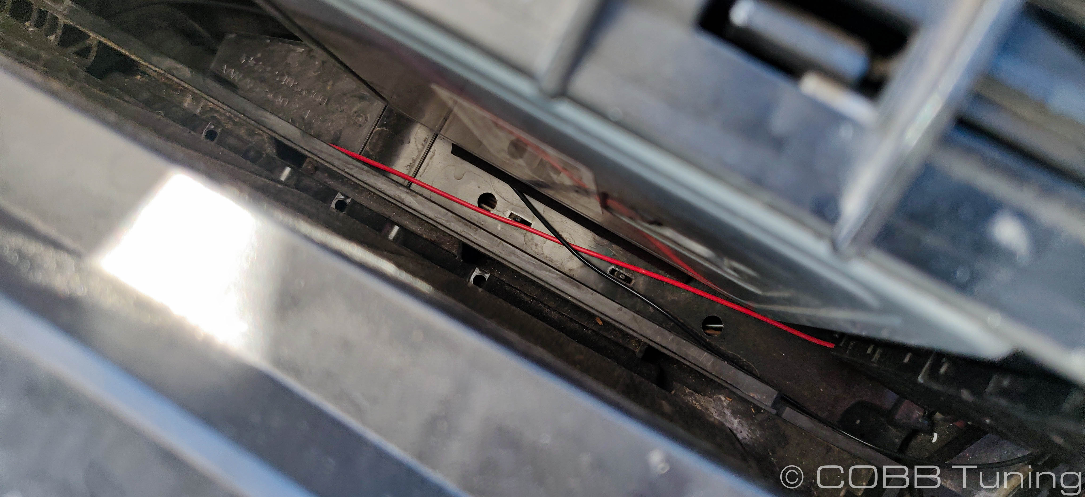
- Route the wiring over the transmission and to the front of the battery tray. Route the positive and negative (black and red wires) under the side of the battery tray to the back side of the battery tray. Leave the white wire near the front of the battery tray. Keep it out of the way of any moving items.
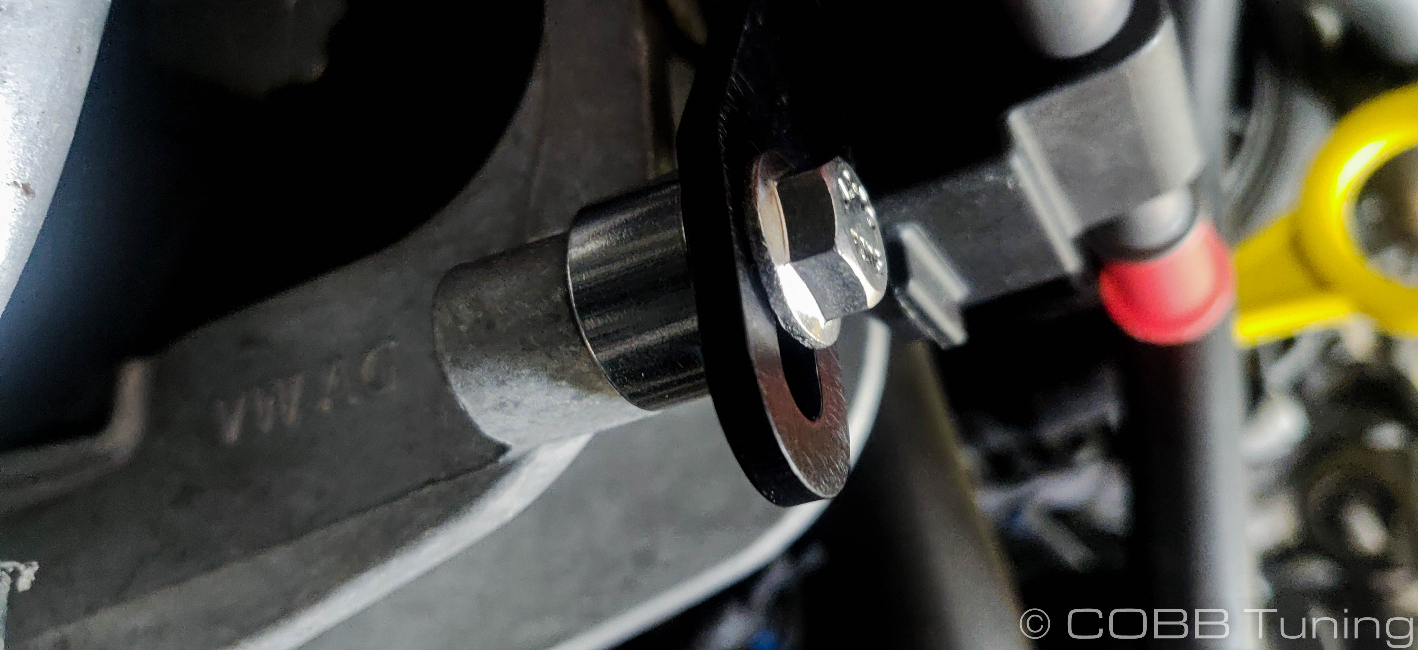
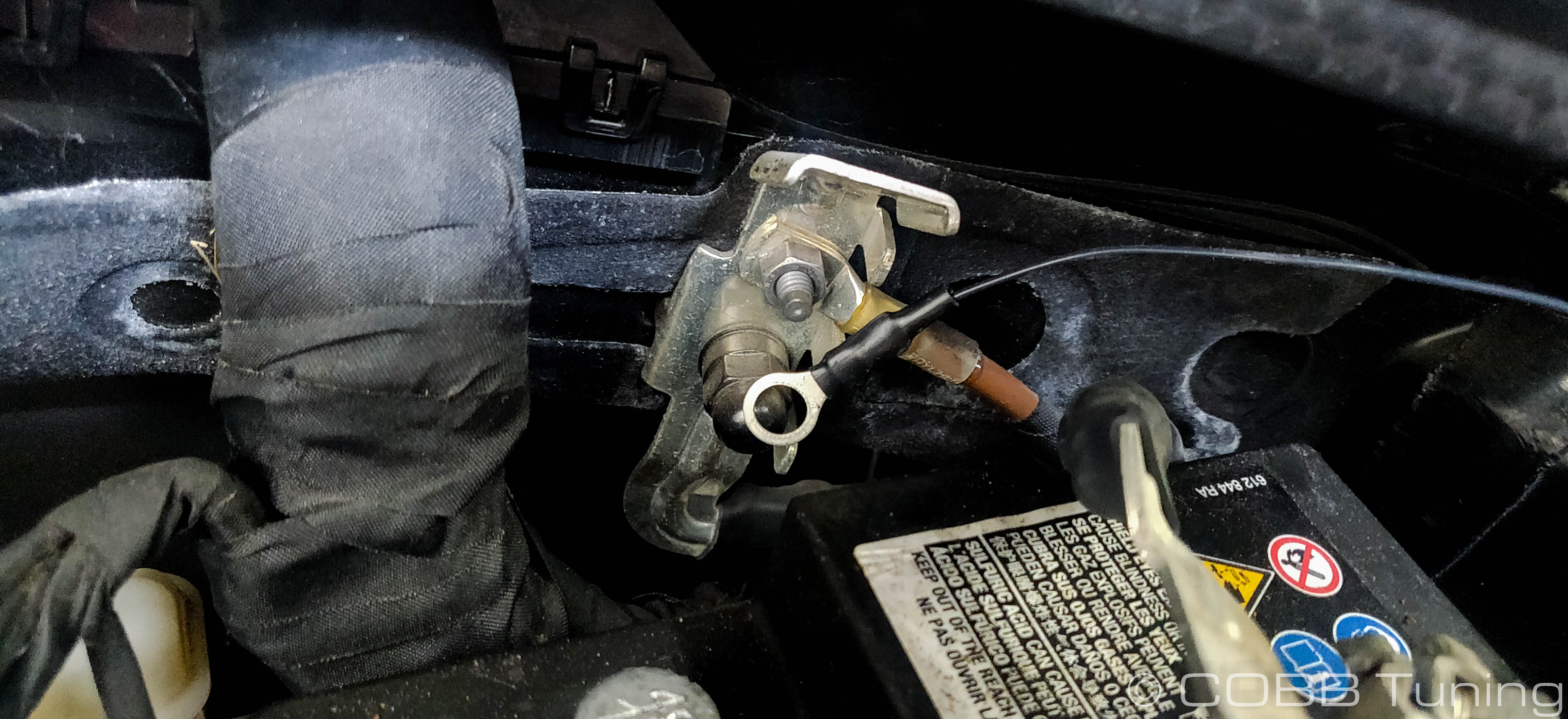
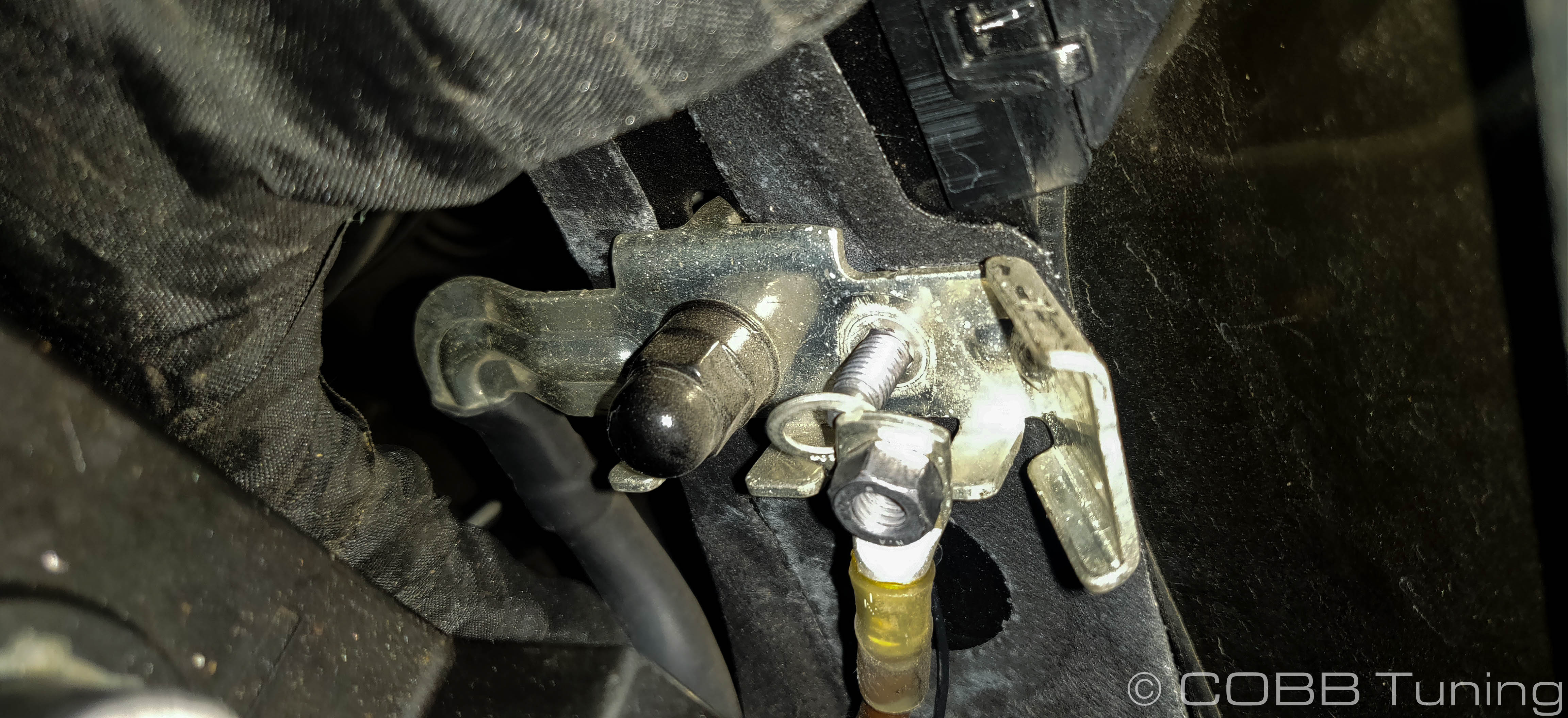
- Unbolt the ground behind the battery on the firewall using a 10mm. Tuck the flex fuel harness's ground eyelet underneath and then bolt it back down.
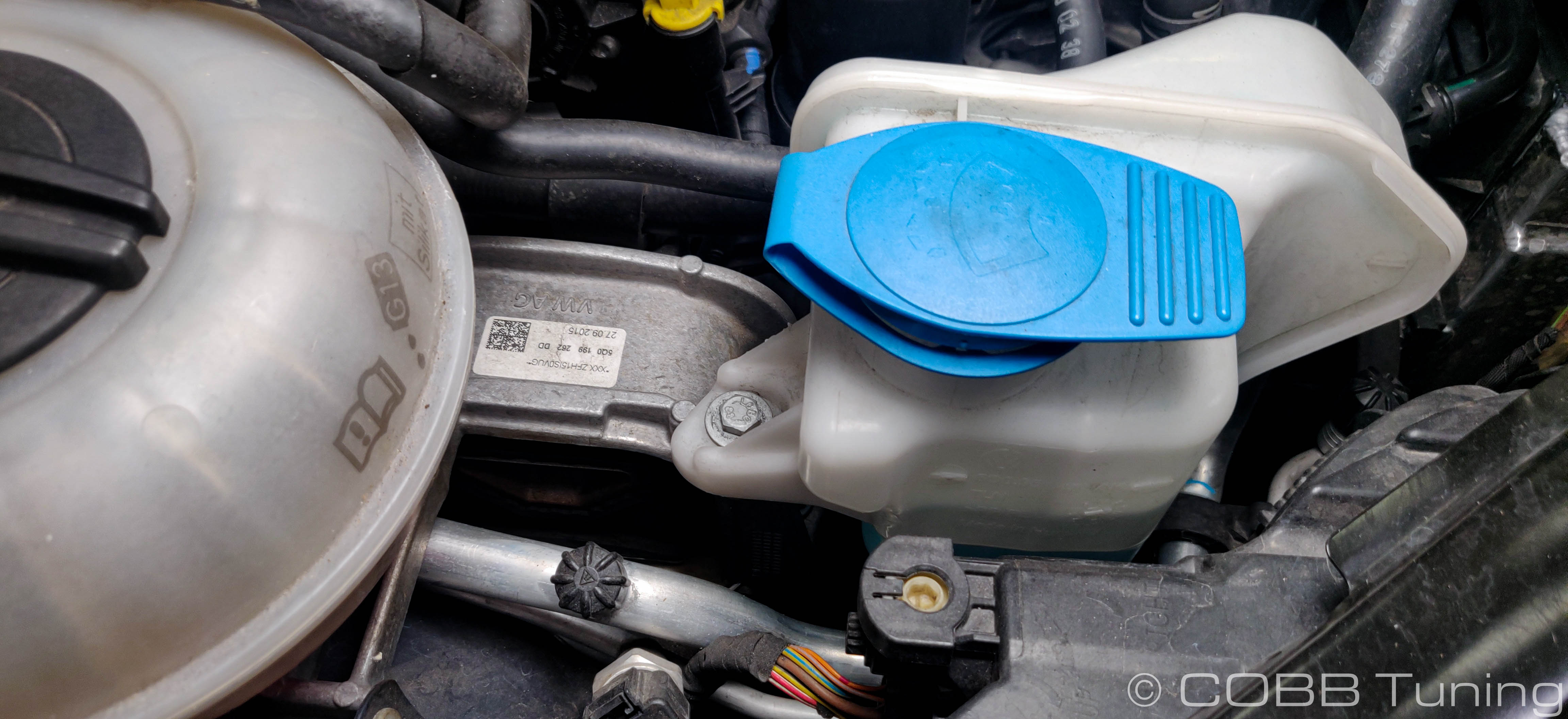
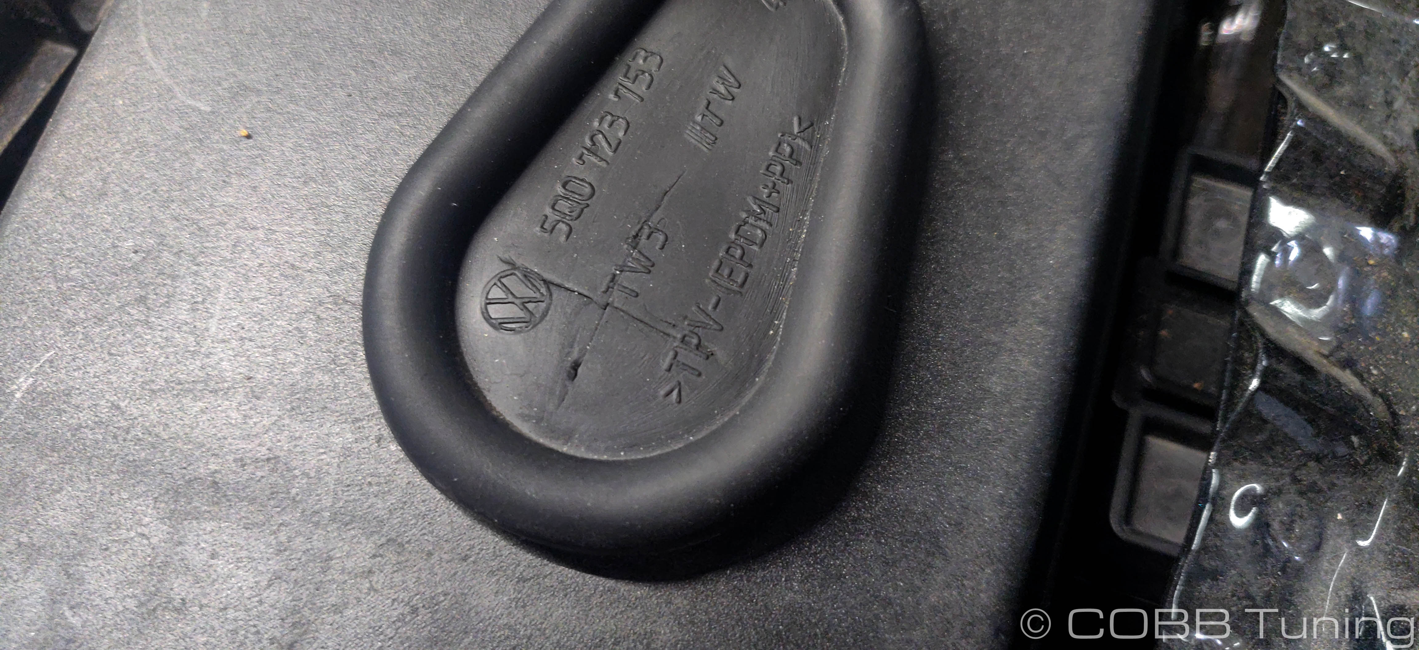
- Locate this grommet on the firewall behind the battery and pop it out. Put a small cross shape cut in the grommet.
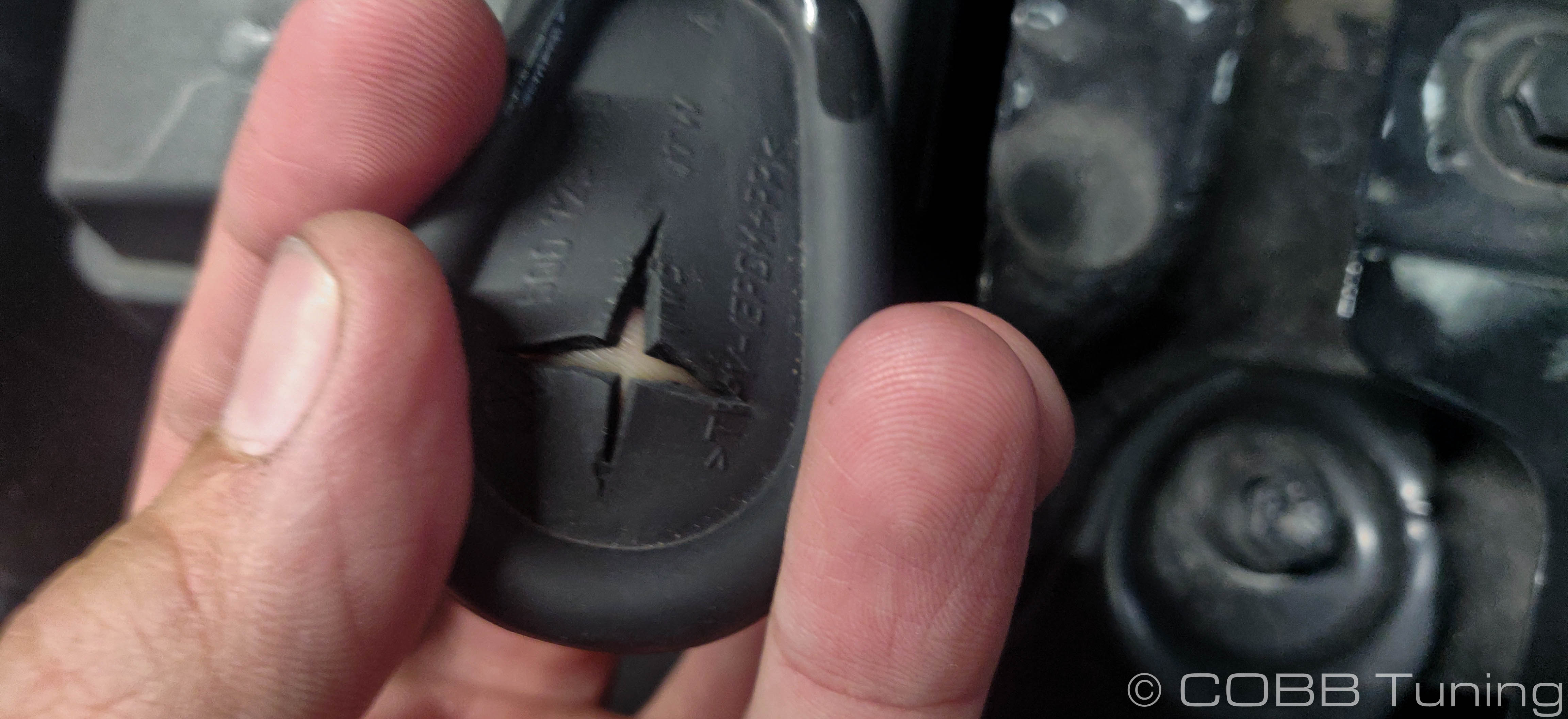
- Route the red wire through the grommet and into the cabin of the car. You can reinstall the grommet.
Pinning The ECU
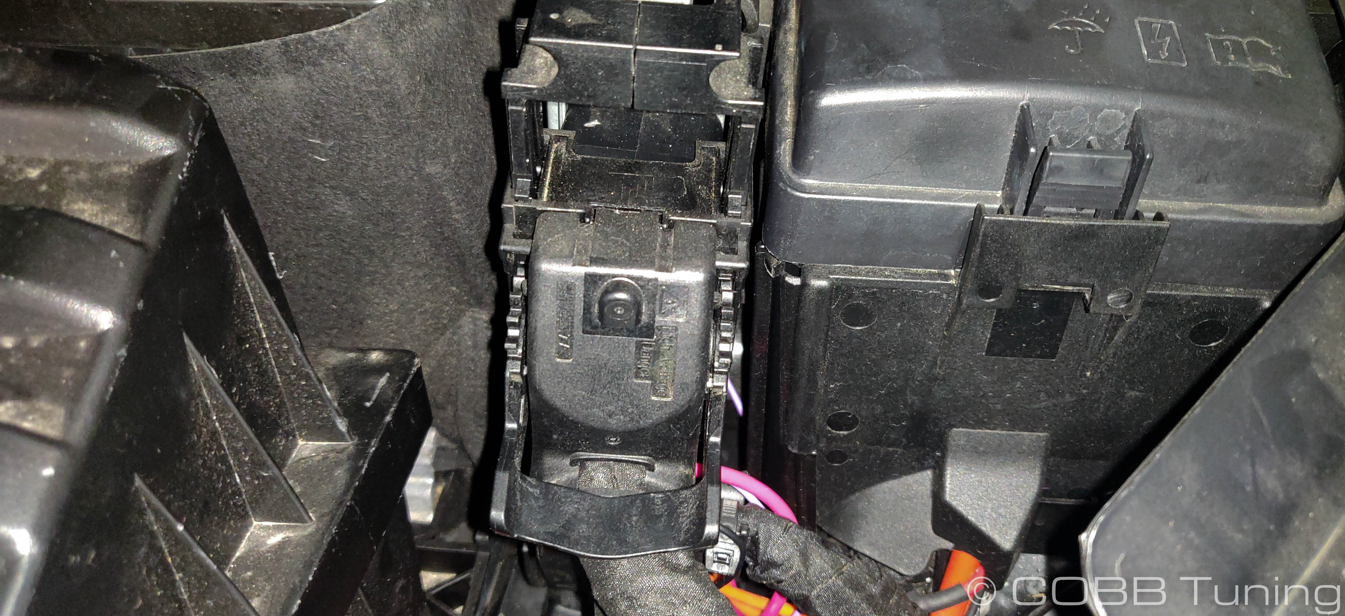
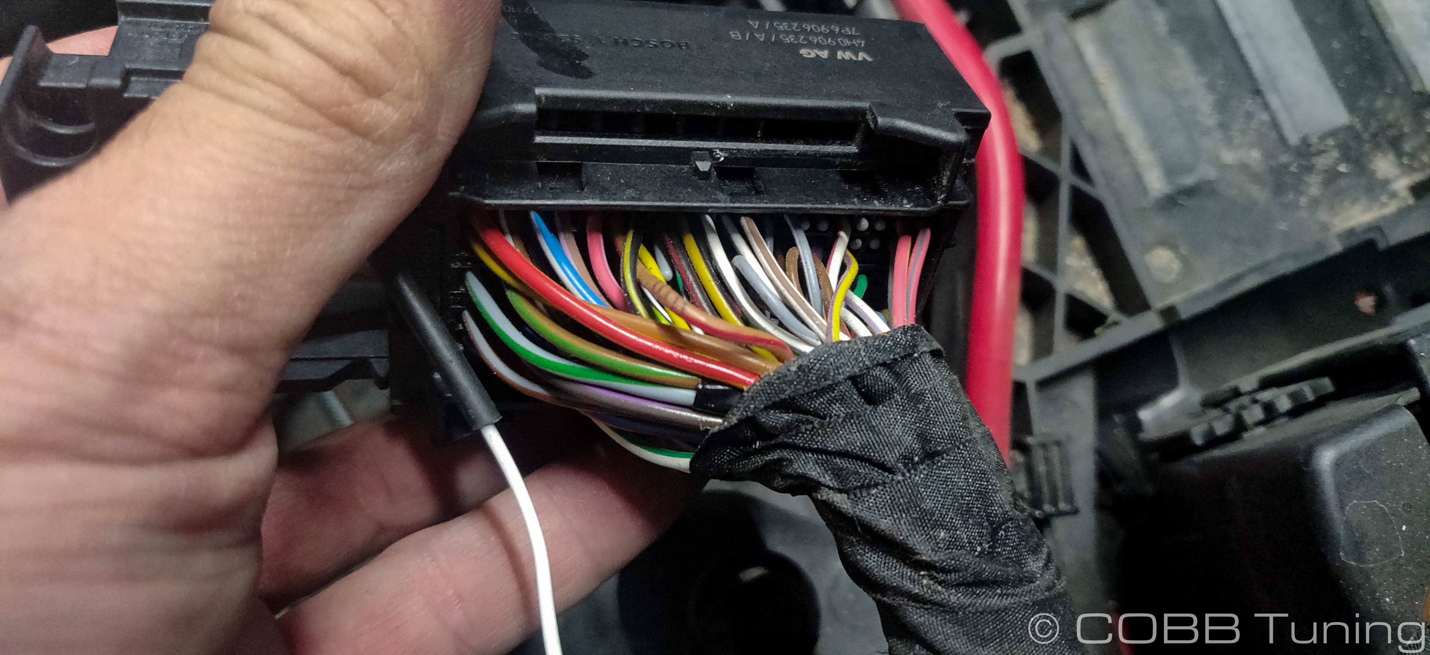
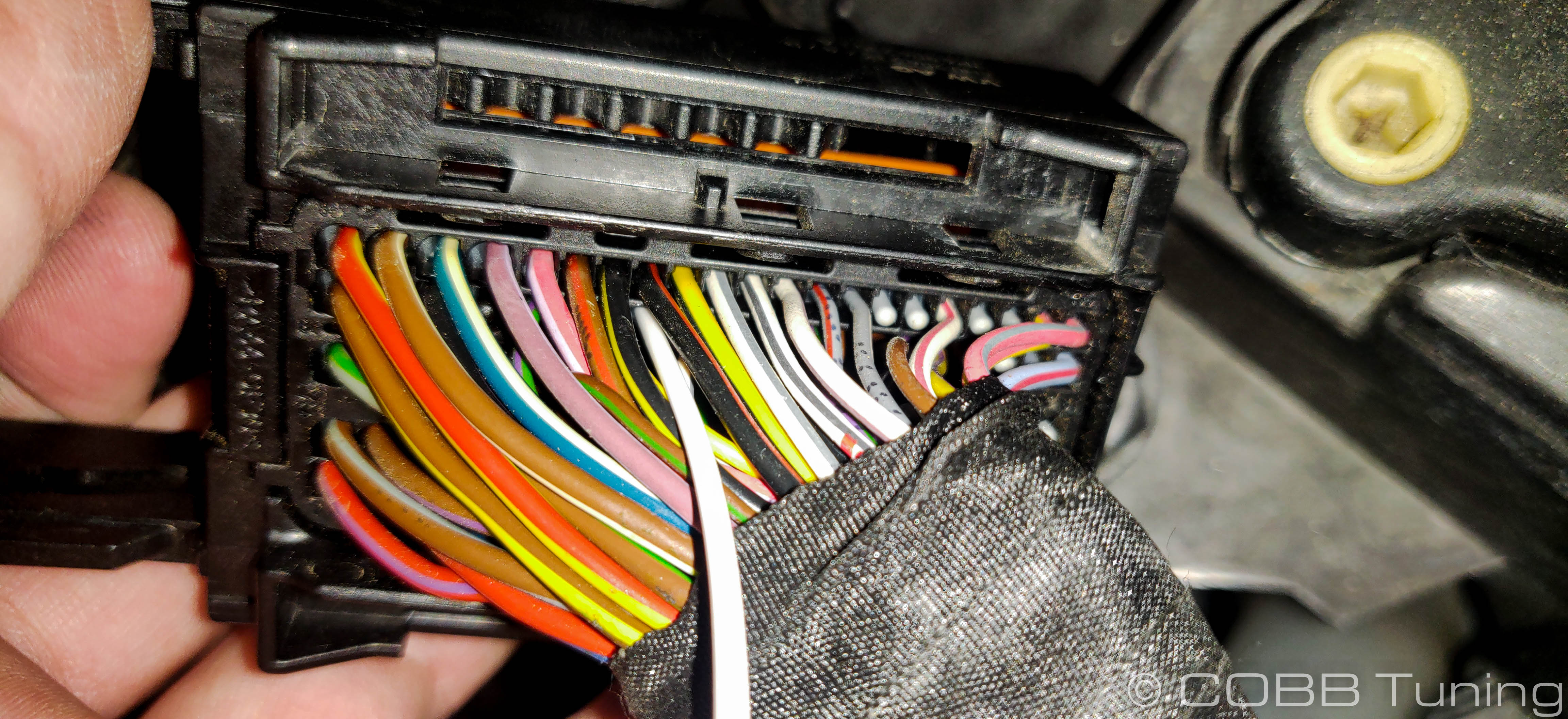
- Locate the top ECU connector next to the fuse box.
- Rotate the lever downwards which should release the lock of the connector and allow the connector to come out of the ECU.
- Using a flat part of a screwdriver, remove the back cover of the connector. You can snip the zip tie to remove the cover off of the harness.
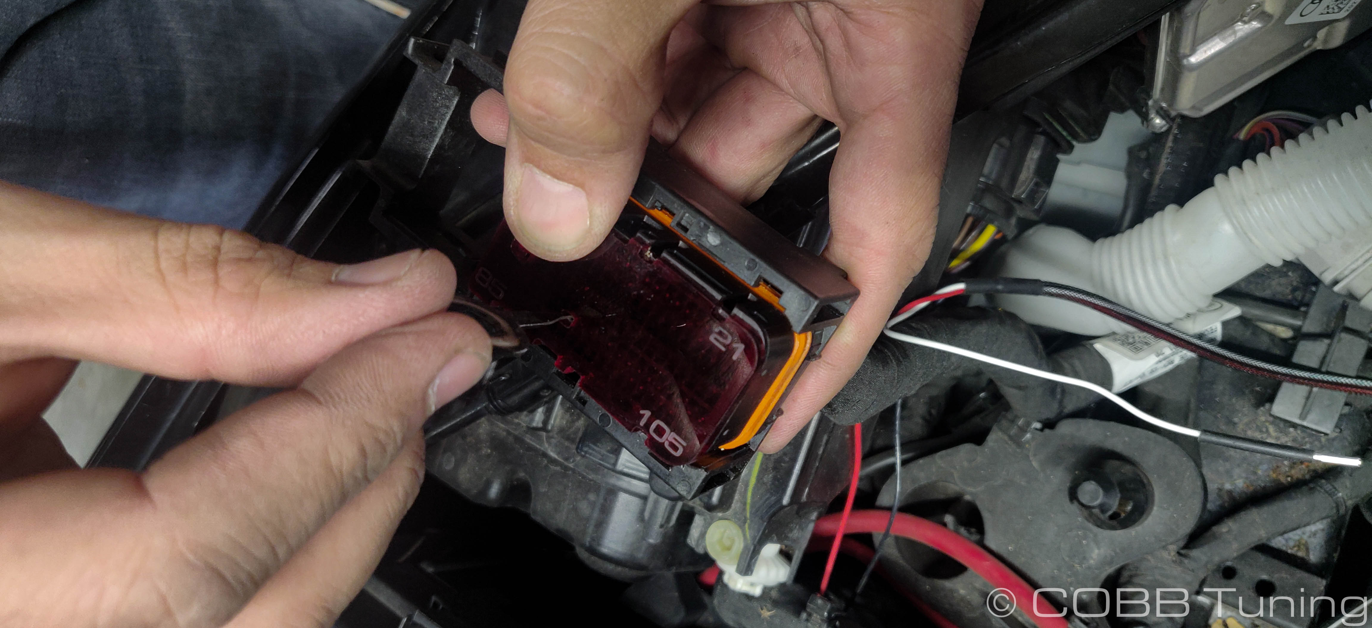
- Using a small flat blade screwdriver, remove the purple lock for the pins off of the connector by levering slightly outwards then pulling it out the rest of the way with your fingers.
- We'll now remove the plastic dummy pin in the connector. Use the provided laser cut pin guide to see which pin you'll need to remove. The cutouts should match with the connector, and the numbers in each corner should match the numbers on the connector.
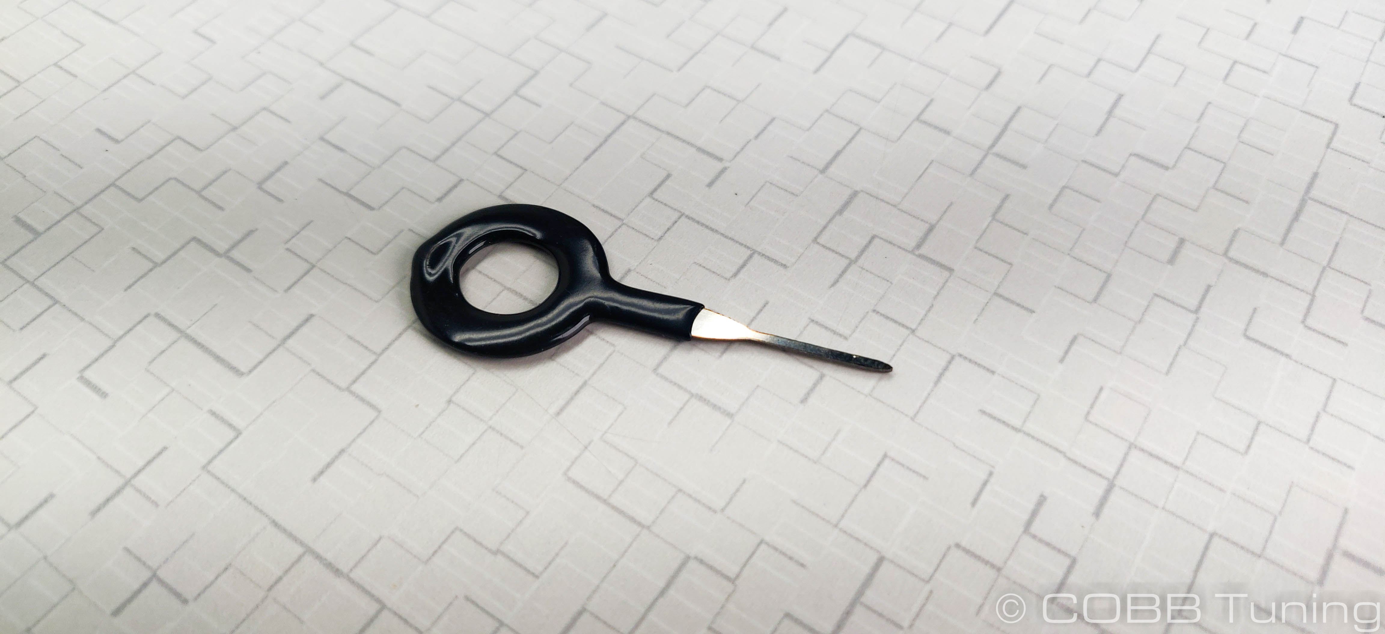
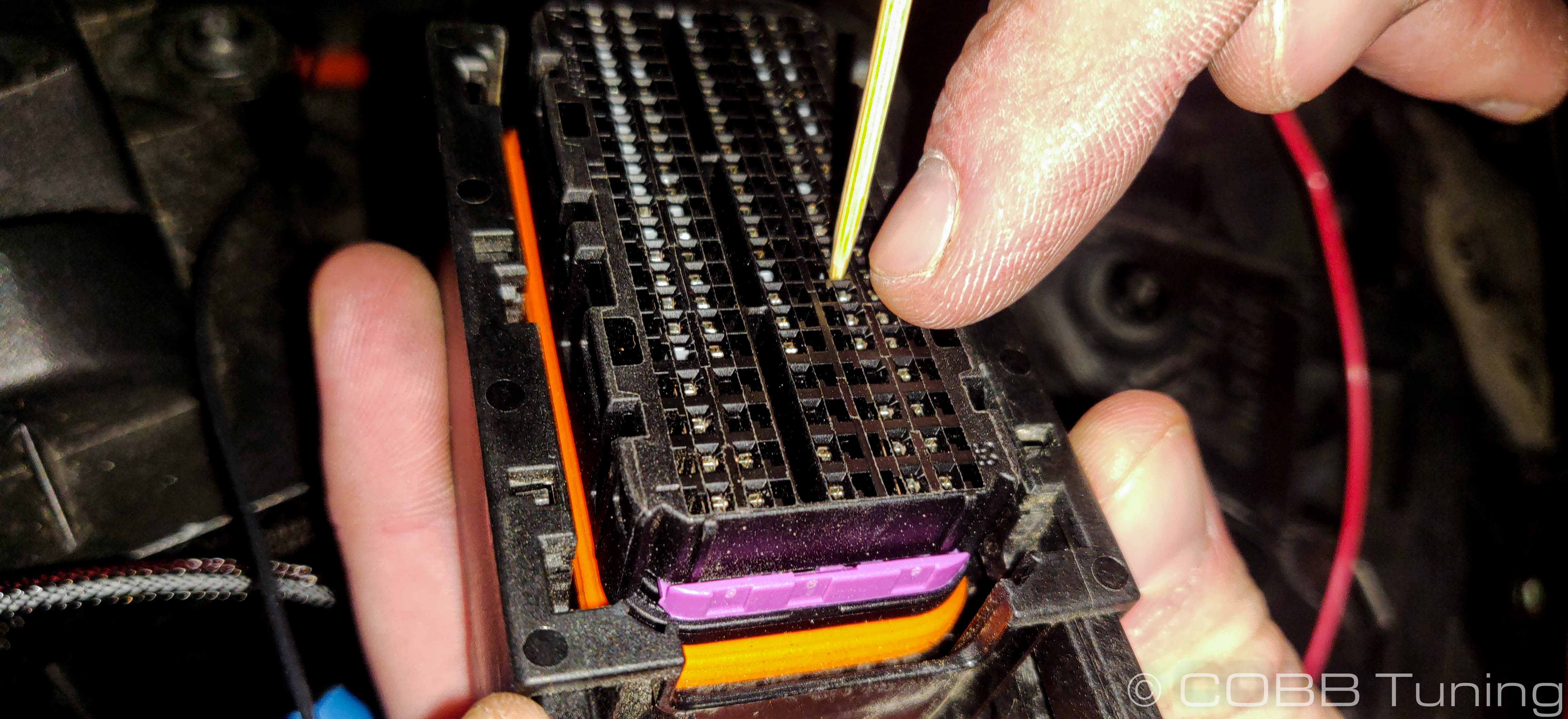
- Using the provided de-pinning tool, push through the hole to remove the pin blank. You can see the grey plastic coming out in the picture below. Keep an eye as to the orientation as this will tell you which way to install the next pin blank.
- Insert the pin in from the back side. Keep it in the position shown below.
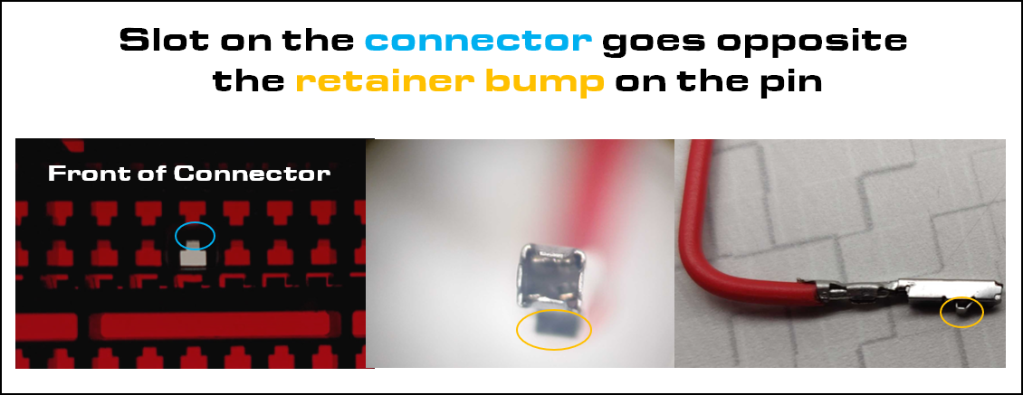
- Push the pin into the connector, making sure to feel it click.
- Gently slide in the purple pin lock. If it doesn't go in, DO NOT FORCE IT OR DAMAGE WILL OCCUR. Pull it back out, it may work best to gently support the wire with needlenose pliers and push the connector in further.
- With the wire successfully pinned, use electrical tape to hold the signal wire to the existing tape on the wiring harness, then reinstall the back cover of the ECU connector. Then ziptie it back in place. It can now be reinstalled into the ECU.
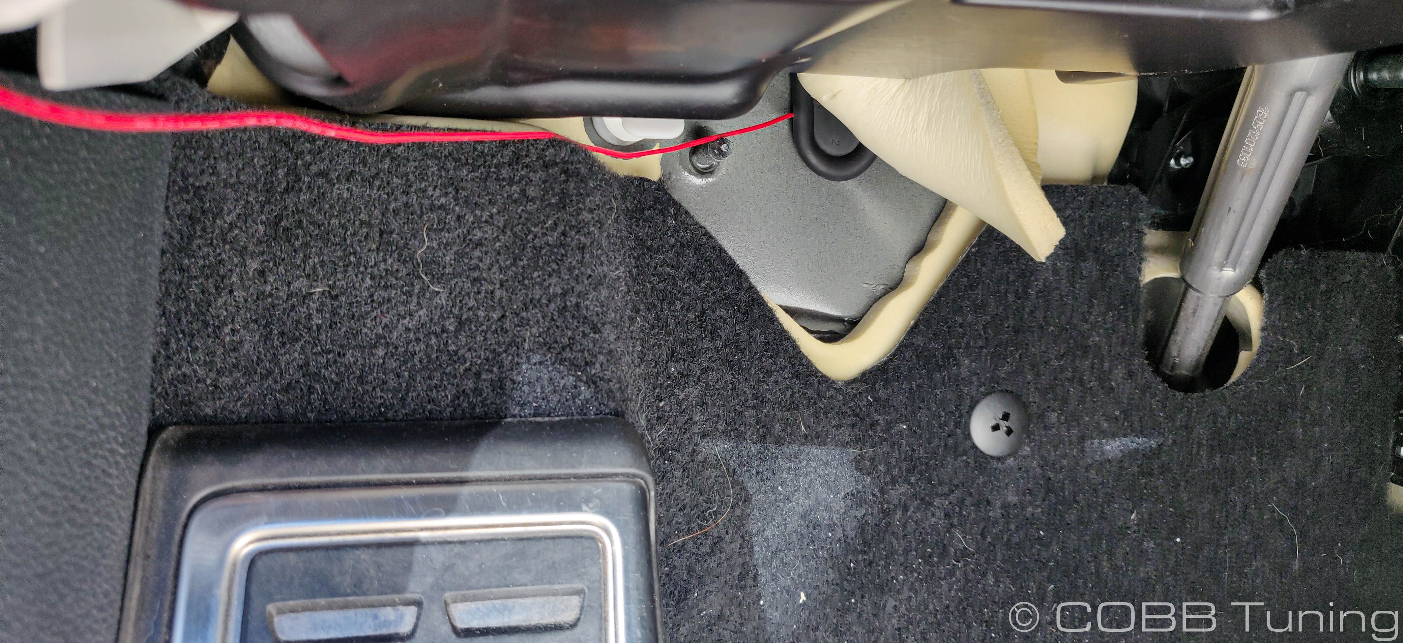
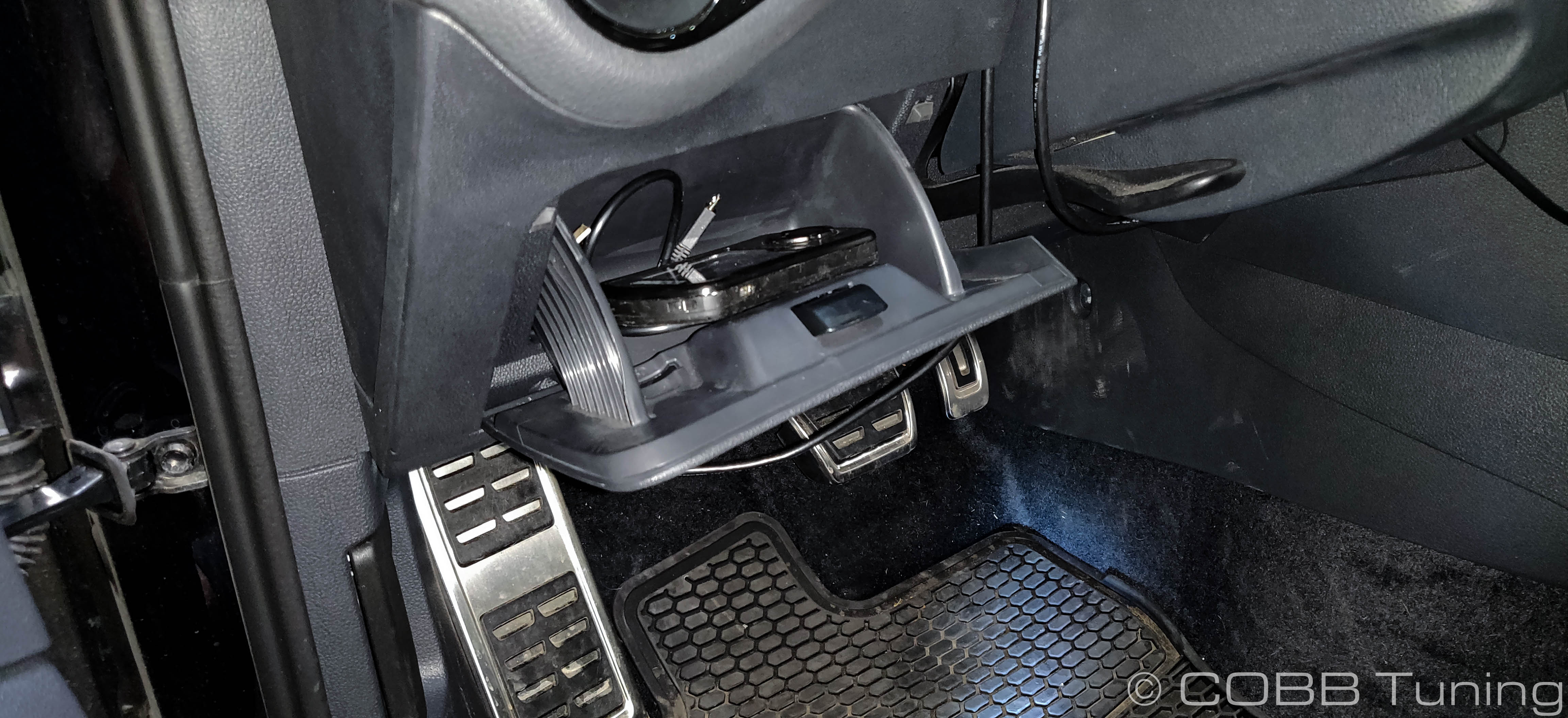
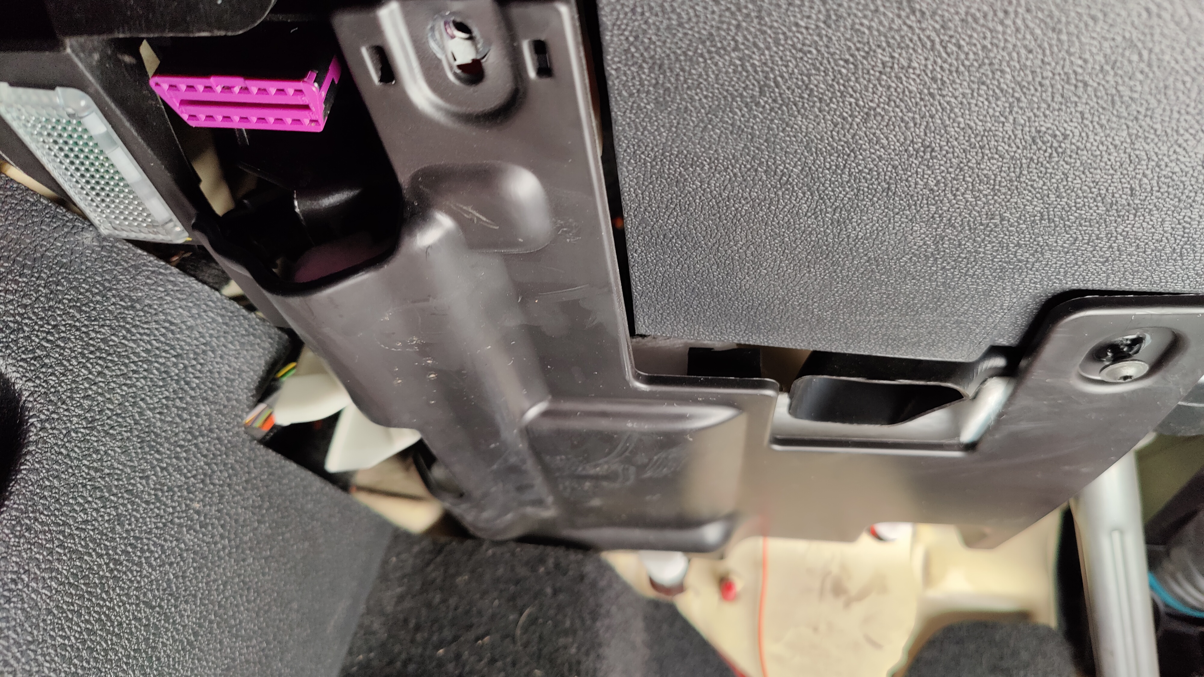
- Moving into the cabin area, Locate the stash pocket next to the steering wheel.
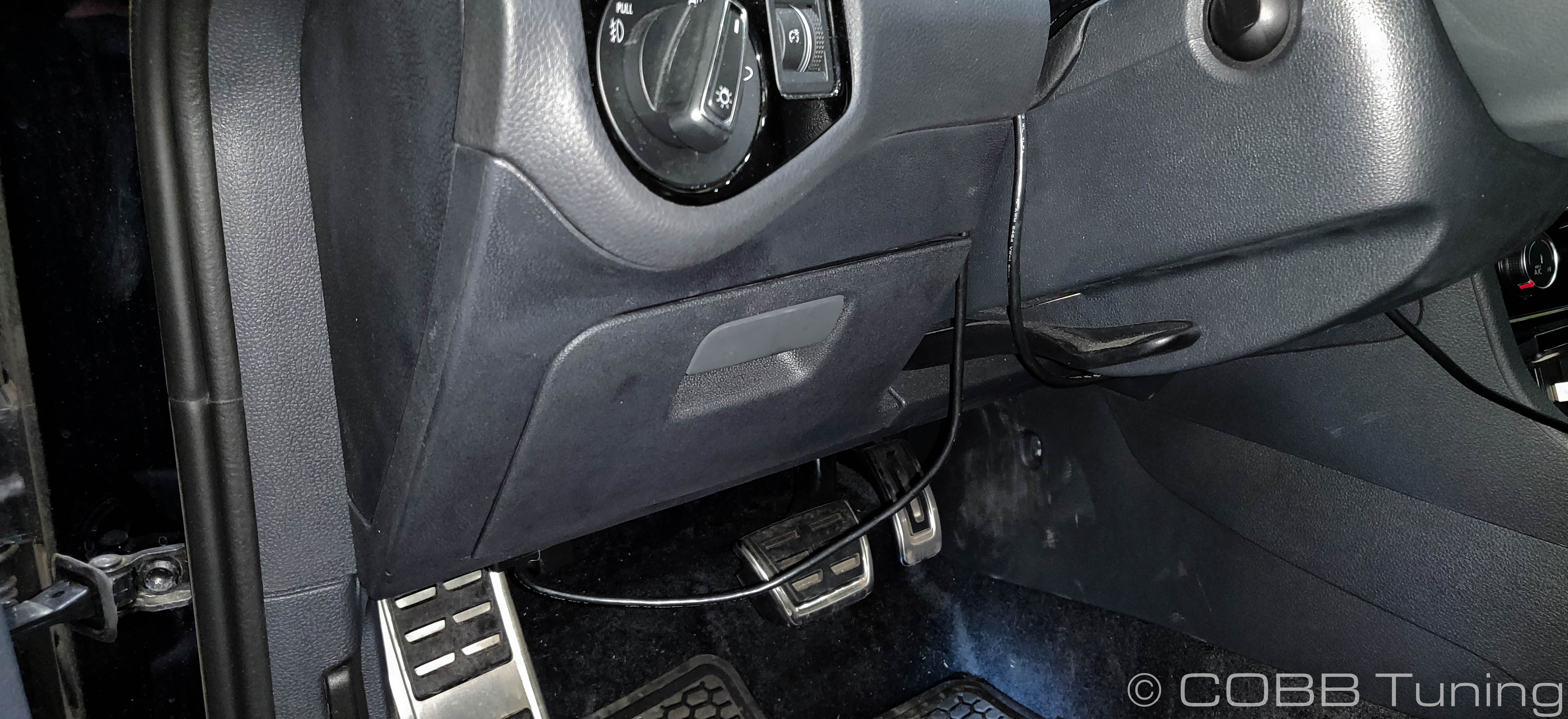
- Open the pocket then gently pull out at the bottom to remove the pocket entirely, exposing the fuse box underneath.
- Remove the cover under the dash by taking out the two torx screws.
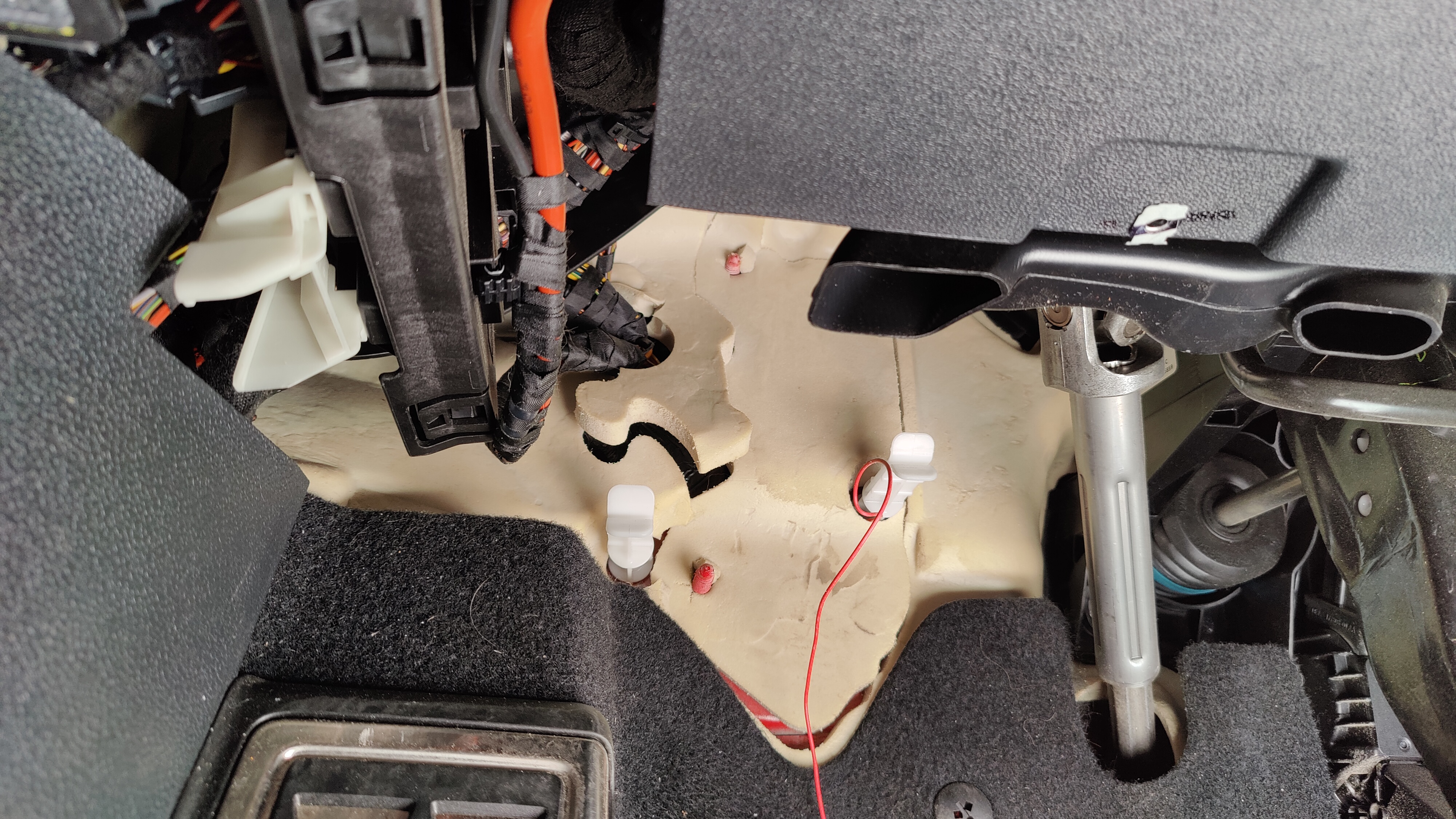
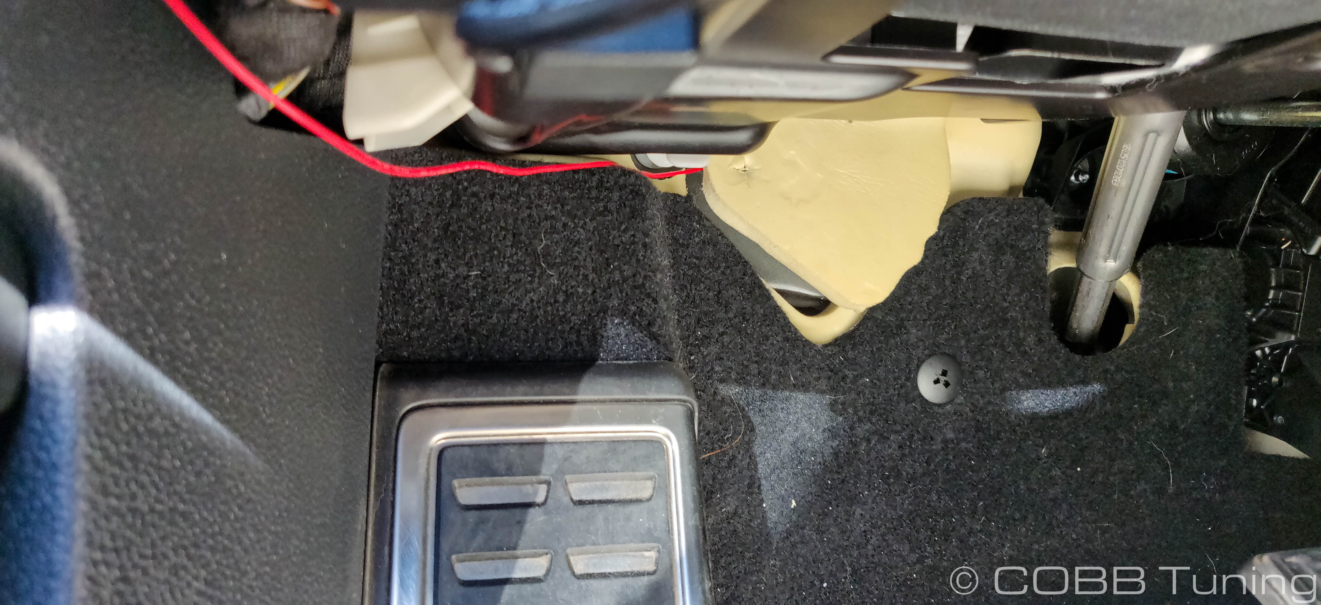
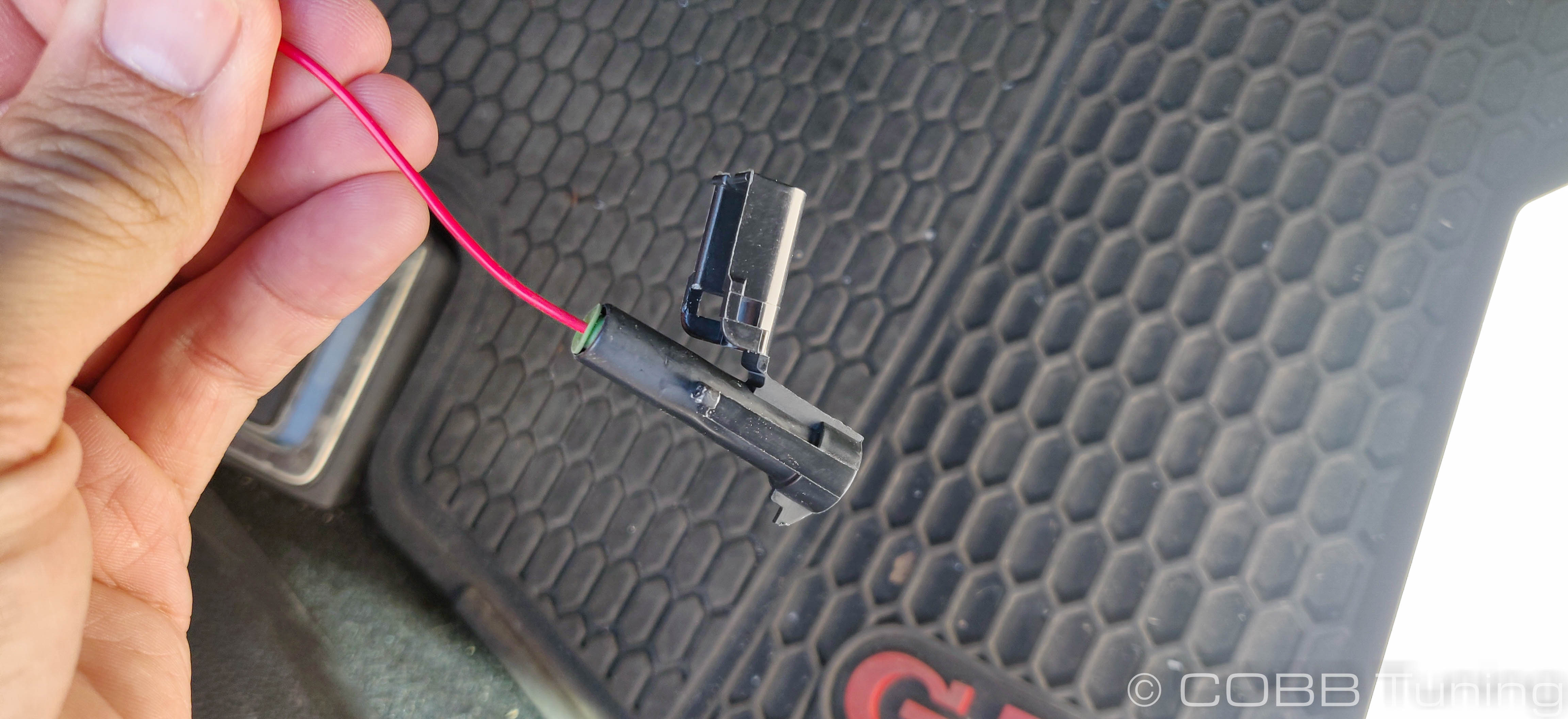
- Route the bare pin end of the Red wire up to the fuse box, making sure to keep it out of the way of the pedals, steering wheel etc.
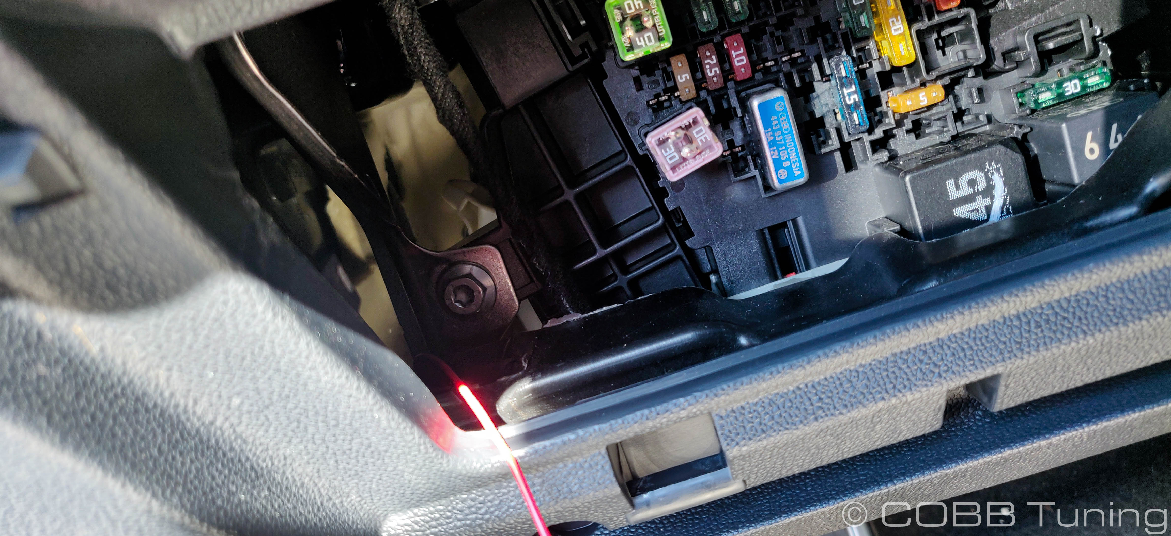
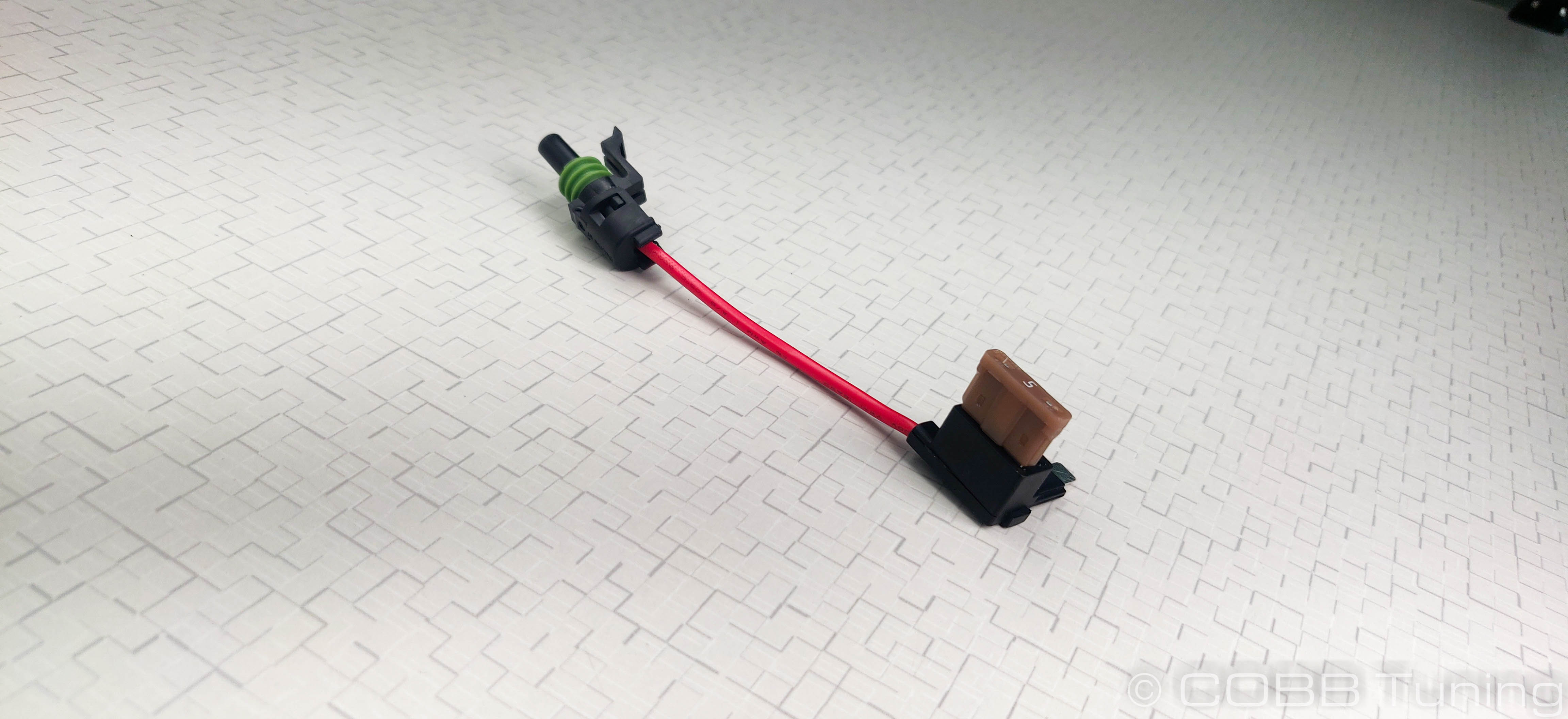
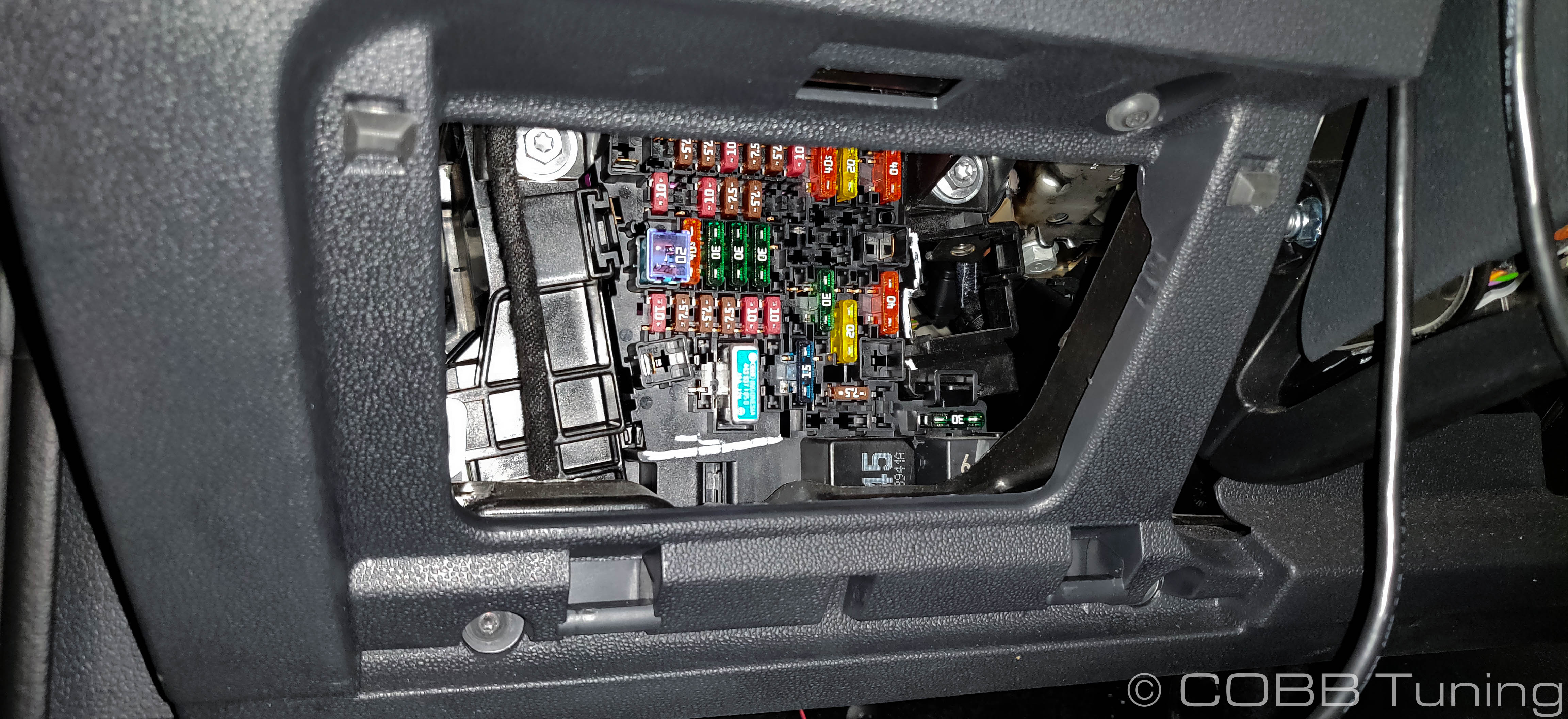
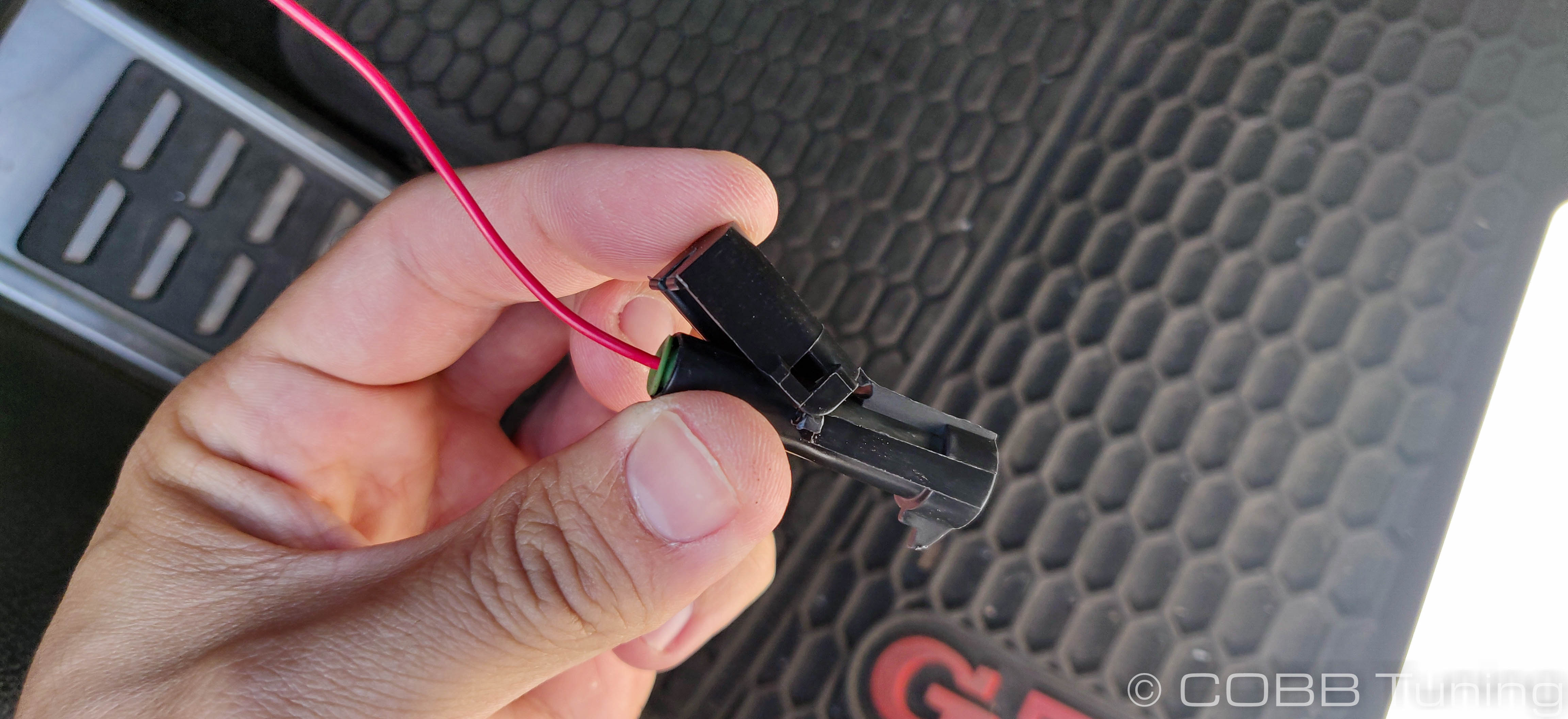
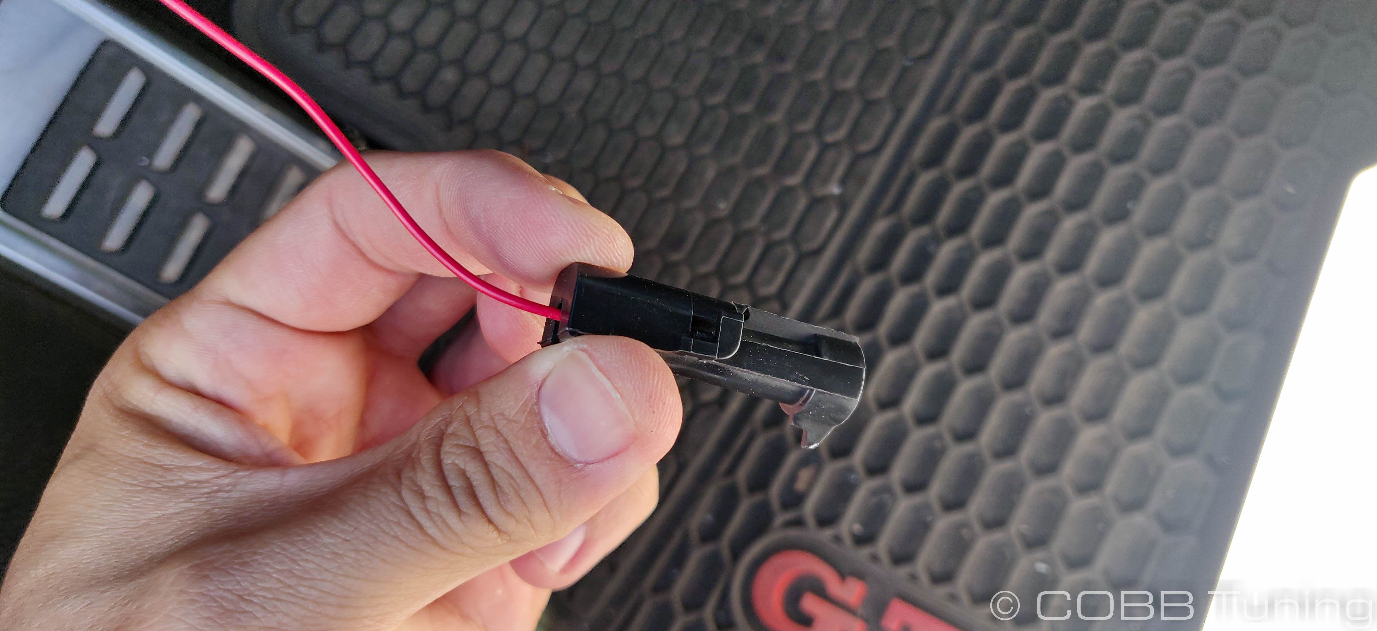
- Push the pin into the connector from the backside then snap the cover down to assemble the connector. you can now plug it in to the provided fuse tap.
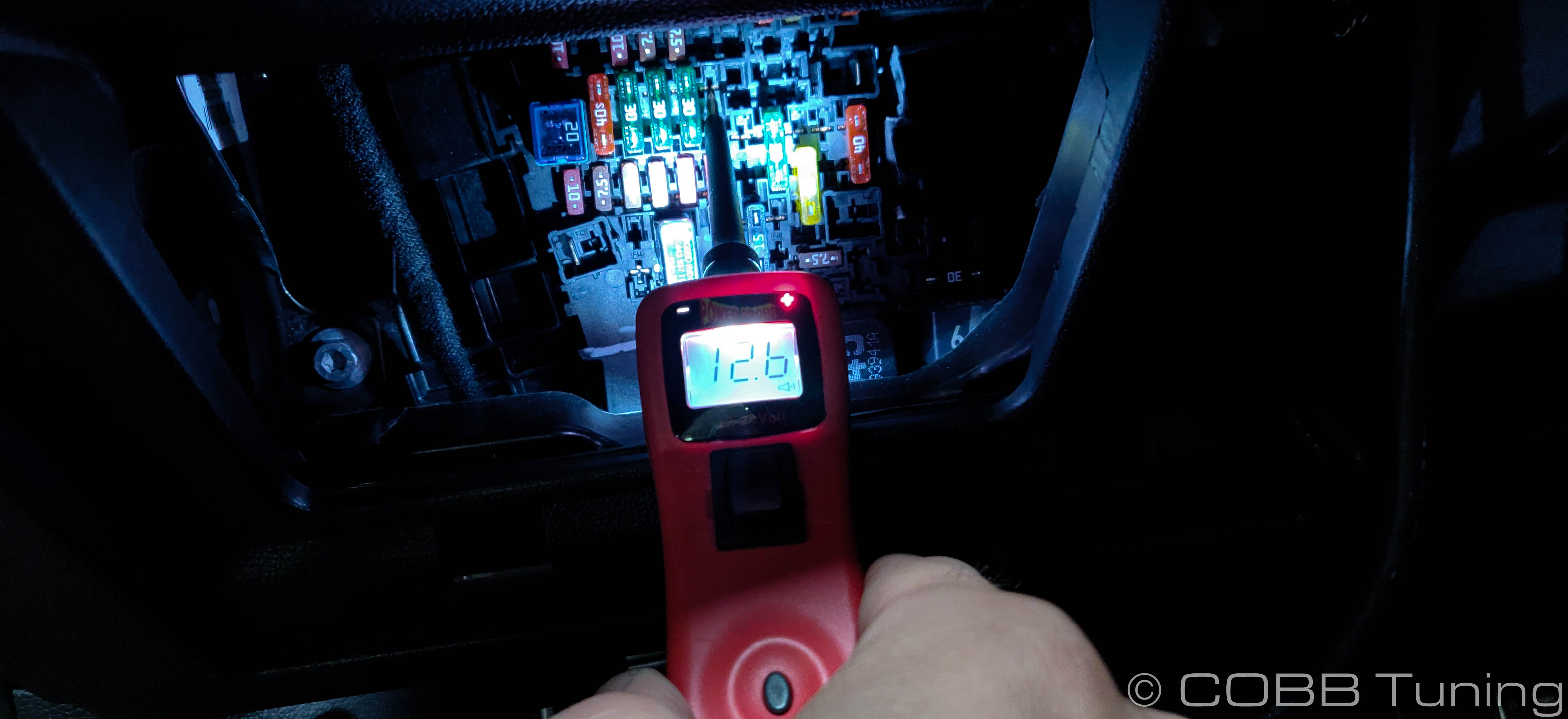
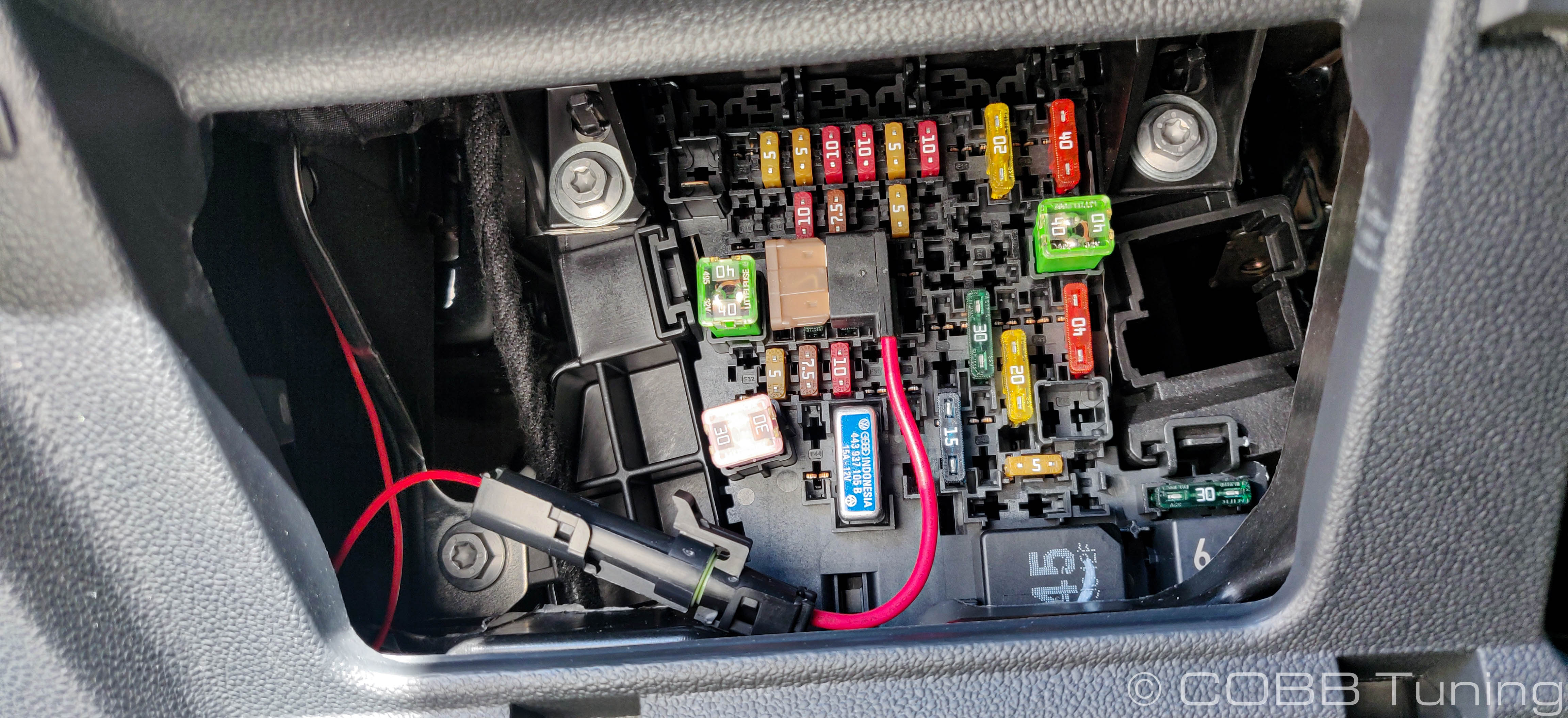
- This can now be installed into an unused slot in the fuse box. We used the one directly after the row of 3 30 amp fuses you can se us probing in this picture. On most cars it should have power when the car is on, but not once it's off. This is preferable to a fuse that is on all the time as it could drain your battery. Depending on what options your car came with you may need to use a different slot.
- You can now reinstall the pocket as well as reinstalling the battery and reattaching the terminals.
- Key the car on and check for leaks from the fuel system.
- Flash your flex fuel map and you should be good to go!
Links
Calibration Map Notes for Volkswagen
Helps to figure out which map you should be on given the parts installed to your car
COBB Customer Support Web Support and Tech Articles: COBB Tuning Customer Support Center Email: support@cobbtuning.com Phone support available 9am to 6pm Monday-Thursday. 9am to 4pm Friday (CST) 866.922.3059 return to www.cobbtuning.comContact Us:
Related content
Copyright 2025 © COBB Tuning Products LLC. All Rights Reserved. | www.cobbtuning.com