Nissan GT-R Tuning Guide
- Brandyn Mowat

![]()
Nissan GT-R Tuning Guide

The following guide is designed to present experienced tuners with an efficient calibration procedure specific to this Accesstuner application.
If you are new to engine management system tuning, we suggest gaining general knowledge and understanding of both calibration and engine dynamics before proceeding at your own risk.
Nissan GT-R COBB Custom Features Guide
- GT-R Automatic Shifting in Manual Mode
- GT-R Auto Shift Point Tuning Guide
- GT-R COBB Boost Cut
- GT-R Cranking Tables And Monitors
- GT-R DBA Timing on CBA Cars
- GT-R Engine Safety Features
- GT-R Enhanced Injector Control
- GT-R Flex Fuel Tuning Guide
- GT-R Fuel Pump Test (Manual Activation)
- GT-R Rolling Boost
- GT-R Secondary/Staged Injection and Multi-Fuel Tuning Guide and Information
- GT-R Traction Control
- COBB Custom Features: Advanced Launch Control Tuning Guide (with BOTL)
Preparation
Update your Accessport firmware, review some helpful documents, and start with the appropriate base map
- Update the firmware on your Accessport to the latest version by following instructions available here.
- Browse to the Accessport support home which includes information on setting up data logging, a key component of tuning and monitoring your engine.
- Review the Maintenance, Updating, and Common Issues: Nissan article, It includes information on common issues on this platform that should be reviewed prior to ensure the vehicle is in good condition to tune.
- We have also included a Help File you can access by pressing the F1 key while the Accesstuner software is open. There's a detailed description of all tables and tuning tips for most tables.
- Please start with a base map that best fits the hardware installed on your vehicle and fuel being used. That information is included in the map description viewable using the Accessport or Accessport Manager software. Alternatively you can review map notes on the COBB website under the “MAPS” section. Be sure to enter your vehicle type so maps for your platform are displayed.
- After completing the above, open your Accesstuner software and complete any available software updates.
- Please make sure the Weighted Interpolation box has been checked. This setting is found in the Display tab of the Configure Options menu, which can be accessed in the software by pressing CTRL+F key. Selecting this will cause Live Trace to appear smoother so you can better identify the current operating condition.
- We have written a detailed description for all tables. You can view this information by enabling the Table Description option under the View menu or by pressing CTRL-F1 while the particular table you want to learn about is highlighted in the table list located on the left hand side of the Accesstuner software.
Choose your ECU
The first screen to appear when opening a new GTR Accesstuner session provides two initial choices.
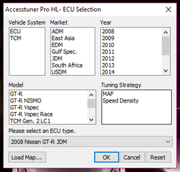
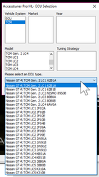
- Select the Vehicle System you want to tune, whether it's ECU or TCM. If TCM is chosen you can choose which LC strategy you want followed by the exact ROM you want to tune on. Keep in mind gen 1 TCM Files cannot be run on a gen2 TCM
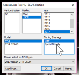
- If ECU is chosen, select your market, year, and ECU.
If you can't find your particular selection, clicking Reset will allow you to start over from the beginning.
Establish safe load/boost targets and limits along with other base settings
Along with adding in any MAF or Injector scaling you have available to you, enabling the safety features and setting up the COBB Boost Cut to safe levels that aren't in the way of what you're tuning can help you keep the car safe during the whole process, and avoid running into any safeties on accident.
Real Time Tuning (Both MAF and SD)
Which Tables are Real Time?
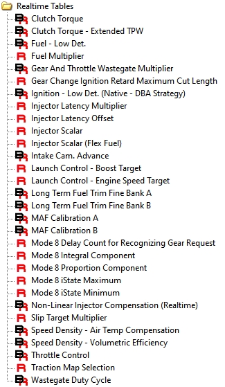
Most tables critical to an engine calibration can be accessed via “real time” tables. These tables are denoted by the red “R” in front of the table. Both MAF and Speed Density tuning is supported via real time. However, just as with non-real time tuning you must choose which strategy to use and complete the appropriate starting point calibration.
What is “real time” tuning? Previously released versions of Accesstuner Pro software required the ECU to be reflashed in order to load and test iterative calibrations. Because the ECU reflashing process takes several minutes to complete, the iterative testing of large numbers of calibrations requires a lot of time and patience. In order to produce a more efficient calibration process the later versions of GT-R Accesstuner Pro incorporates “real time” tuning strategies. Nearly all critical ECU tuning tables can now be changed live and in “real time”. Changes are immediately loaded to the ECU and can be tested WITHOUT reflashing the ECU. This new feature, an exclusive of Accesstuner Pro, promotes efficiency with a more precise calibration as the final product.
Tables marked with an "R" are "Realtime" and tables marked with a "B" are base tables utilized in all of the switchable maps. Tables marked with an "S" are tied to a specific switchable map. It isn't possible to have a switchable map to change between SD and MAF without completely reflashing the vehicle.
Workflow for real time tuning:
- Create a starting point calibration using real time capable software.
- Flash this map onto the ECU using the Accessport or Accesstuner pass through flash.
- Start the car and connect to the Accessport and ECU using “pass through” mode where the ECU, Accessport, and computer are connected in a serial manner.
- Using the cruise control map switching feature select the appropriate map slot (Active Map Slot) you wish to tune. Verify the active map slot by viewing the “Active Map Slot” monitor in the dashboard after you connect to the car in step 5.
- Press “Ctrl L” to connect to the live ECU. The real time tables will now contain the ECU values in from the map slot you just loaded. DO NOT change active maps using the cruise control while tuning in real time.
- Make changes in the “real time” tables and watch the monitor icon in the lower right hand corner of the Accesstuner go from green (indicating an online status of a live ECU) and briefly to red (indicating a write process to real time data).
- Real time tables are stored in RAM in the ECU and are therefore volatile. In order to save changes permanently in a calibration copy and paste the table into the corresponding switchable table in the map slot of your choice. Switchable tables are denoted by a blue “S”.
- To copy changes from realtime to any switchable table you can use the “Map Slot Copy” tool. “Copy Tables” will bring up the map slot copy dialogue box
- When copying a map slot you have a choice to copy every table within said map slot or select specific tables (toggle “Specify tables to copy” check box).
- Once a fully acceptable calibration is created and all data saved to the appropriate switchable map save the calibration under an appropriate name and then flash it to the ECU.
- Switch through active map slots using the cruise control map switching feature and refresh real time tables (press F5) and make sure real time tables match corresponding map slot data.
Base vs Realtime Maps
Note that some tables are marked with black letter “B” These tables are used in all of the switchable maps (up to 9) contained in each calibration file. In other words, these tables are referenced for every functional map in a single calibration. Base tables are the SAME for MAF or SD based tuning. Tables marked "R" are adjustable in realtime, while those marked "S" are switchable for map slots 0-9.
MAF vs SD
For Specific notes on tuning in each style check out the below guides.
Nissan GT-R Speed Density Tuning
Switchable Maps
Default Switchable map count is determined by the tuner, from 1-9 maps can be enabled. The default number is 4. This is adjusted in the "Global Map Settings:Active Map Count" table
When switching maps with the cruise control, you'll select the cancel button for the cruise control then go up or down to change positions. This will be visible on the Boost gauge of the vehicle. With each map slot moving progressively upwards.
Map Slot 0
Map Slot 1
Map Slot 2
Upgrading MAP Sensors
As turbo options and built motors have become common in R-35 GTR aftermarket tuning so has a need to introduce higher reading manifold absolute pressure sensors. There are a total of 3 MAP sensors in a GTR. Two sensors are located before the throttle bodies on each side of the manifold. The third map sensor is located on the manifold. Importantly, it is this third map sensor is used to calculate load for speed density tuning. It is also important to use a MAP sensor that reads higher than desired boost – even when using MAF based tuning – so that a usable boost limit is maintained.There are two values used to calibrate both the pre and post throttle the MAP sensor: gradient and offset. The post throttle MAP sensor is the critical sensor used for load measurement on Speed Density calibrations. There are two values used to calibrate both the pre and post throttle the MAP sensor: gradient and offset. The post throttle MAP sensor is the critical sensor used for load measurement on Speed Density calibrations.
Precautions for Map Sensor Saturation
Sensor limits – Engine control is dependent upon accurate readings from the MAP sensor. Beyond the limits of the stock MAP sensor (Approx. 4.84 volts) the ECU has no way to properly control the engine. Any turbocharger upgrade must also be accompanied by an appropriate MAP sensor. If the sensor limitations are met, the car can produce a fuel cut condition. The problem results from maxing out the Pre-throttle MAP sensors. When this occurs an alternate fuel state is entered and any load then produces a fuel cut. A data log will show this as injector pulse-width returning to a near idle value. If this issue is experienced, (CTO!) disabling DTC's P0241 and P0242 will remove the sensor checks allowing the engine to run outside of the sensors range. These DTC's should only be used as a diagnostic aid as this removes the ECU's ability to determine if a sensor is defective. If this test isolates the issue, appropriate MAP sensors should be selected for the vehicles targeted boost level.
5 Bar MAP sensor upgrade - toggles promoting proper high capacity MAP sensor calibrations.
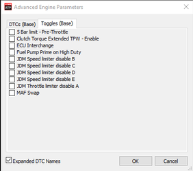
Any 5 bar MAP sensor requires a larger calibration value for gradient than is allowed in the ECU. For example, an AEM 5.0 bar map sensor reads from 0.5 to 4.5 volts. So, the desired gradient value is 125 KPa/V. Unfortunately the maximum input for this is 102. To obviate this issue and properly calibrate similar sensors you must check the “toggle” under advance engine parameters (control-alt-A). By checking the “5 Bar limit” toggle you HALVE the needed gradient value for the MAP sensor calibration. In this example, the needed value of 125 Kpa/V, with the toggle checked, can now be entered as 62.5 (125/2 = 62.5). This is below the allowable unit limit of 102 for the ECU but is understood and calibrated correctly because the toggle adds an extra logic step to effectively double to value within the ECU.
This 5 bar MAP sensor calibration is only available in Speed density based calibrations. It is assumed that any tuner who needs to run this much boost will not attempt to do so with MAF based conventional GTR tuning.
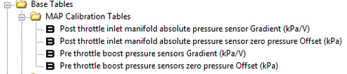
Map Sensor Scaling Tables
The Following Tables are utilized when changing the map sensor scaling.\
- Post Throttle
- Post Throttle Inlet Manifold Absolute Pressure Gradient
- Post Throttle Inlet Manifold Absolute Pressure Sensor Zero Pressure Offset
- Pre-Throttle
- Pre Throttle Boost Pressure Sensors Gradient
- Pre Throttle Boost Pressure Sensors Zero Pressure Offset
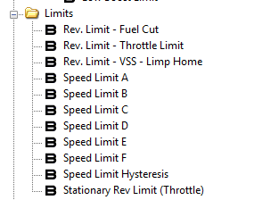
Removing Speed Limiter Cap from JDM GT-R
Model year 2009-2011 JDM GT-Rs have additional limiter toggles to address the speed limiter cap. You'll want to toggle all of the options found on the “Advanced Engine Parameters” toggle list. Use these toggles be sure to review the Speed Limit tables as well, then adjust the speed limiter value needs to be set accordingly.
MAF Bank Switch for intercoolers with non-standard Airflow
The Stock GT-R intercooler has the turbo from one side, feeding the throttle body going to the opposite bank. Some aftermarket intercoolers change the airflow through the motor in such as way as to have the turbo providing the airflow for the same side. In order to correct this the tuner can either re-wire the MAF sensors to read from the appropriate side of the motor OR the tuner can simply enable the MAF bank switch toggle to change MAF banks inside the ECU.
Calibration Refinement on Load-Based Chassis Dynamometer
Configure and connect Accesstuner Software to the Accessport Equipped GT-R
Open the selected starting point calibration in the Accesstuner software. Configure the Accesstuner software to connect to your vehicle. Attach the OBDII dongle/cable to the vehicle and the associated USB cable to your computer (direct tuning). Alternatively, connect the Accessport to the vehicle and then simultaneously connect the Accessport to the computer. Used in this so called “pass through” configuration the tuner can connect to and collect data from the vehicle and, without changing any physical configuration, flash a new calibration to the car's ECU.
Select the directory in which to store your data logs under the “logging” tab. Select the type of tuning cable and its associated com port under “communications.” You can also integrate a wide-band oxygen (WBO2) sensor signal into the data logs. Select the specific oxygen sensor you wish to use and indicate its associated com port.
External Wideband Operation
In some instances it may be helpful to utilize an external wideband sensor. For more information on how to do so check out our related article.
How to Connect your Wideband to Accesstuner Software
Display and Log Critical Engine Parameters while Testing
Accesstuner software allows the user to visualize, sample, and record critical engine parameters. This data includes sensor information and commanded engine function.
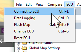
To connect to a live ECU:
Open Accesstuner and load the calibration currently flashed into the vehicle. Attach the OBDII cable to the vehicle and the V3 Accessport, then connect to the computer using your USB Micro Cable. In order to connect you can go to the ECU section and select "Connect to ECU" or use the keyboard shortcut Ctrl+L. If Accesstuner is connected to the vehicle the message in the lower right corner of the program will read “on-line.”
Configure displayed parameters on the live “Dashboard” and those data collected during a log:
The parameters selected in the “Gauge List” tab will be displayed in the live dashboard when connected to a vehicle and the live dashboard is enabled. This screen is the single best way to assess the condition of the engine during tuning. It is critical to actively monitor these parameters while tuning. These data monitors allow the tuner to determine if a calibration is performing correctly. Accurate and deliberate assessment of engine data is the only way to avoid conditions that may damage the engine.
Accesstuner software allows the user to visualize, sample, and record critical engine parameters. This data includes sensor information and commanded engine function.
Configure displayed parameters on the live “Dashboard” and those data collected during a log:
The parameters selected in the “Gauge List” tab will be displayed in the live dashboard when connected to a vehicle and the live dashboard is enabled. See an example of this live dashboard below. This screen is the single best way to assess the condition of the engine during tuning. It is critical to actively monitor these parameters while tuning. These data allow the tuner to determine if a calibration is performing correctly. Accurate and deliberate assessment of engine data is the only way to avoid conditions that may damage the engine.
Below is a list of logged parameters for the GT-R (MAF or SD based tuning). The selected parameters are those that are critical to record under most conditions. Other parameters may be selected or removed based upon the objectives of any specific tuning process
Perform Initial testing at Lower Boost
After choosing the most appropriate starting point calibration, prepare to test and refine the calibration on a loadbased chassis dynamometer. When creating a custom tune, it is best to begin testing under low load conditions. COBB Tuning GT-R calibrations discard the factory Nissan boost control in favor of our own boost control system that is throttle position, gear and RPM dependent. COBB Tuning GT-R calibrations include special coding that support a more simple and elegant proportional gain based boost control system. To lower boost reduce wastegate duty cycle in “wastegate duty cycle”. This boost control system is further refined by changing the wastegate gain as a function of throttle position and gear. Additionally making use of the various COBB Custom compensations and boost cuts we offer can ensure stable levels of boost.
Injector latency offset and multiplier–When using injectors other than stock it is critical to adjust these values to reflect the voltage response characteristics of the new injectors. Injectors need a different dead time compensation at different voltages. Generally, lower battery voltage requires longer dead times while higher voltage requires less. This relationship is defined by two variables in the GT-R ECU:
- Injector “offset” is the amount of open time/latency added to a calculated open time at 14 volts battery voltage
- Injector multiplier defines the slope of the linear relationship between battery voltange and injector latency.
Injector scalar – The injector scalar is defined in cubic centimeters (CC). The stock injector size is 570cc. To change the injector size simply input the new injector scalar in cc. (conversions of arbitrary units as was needed in earlier versions of the software are no longer required.)
Tuning Ignition Timing
DBA 2011+ World Market, 2012+
Example Data 1 – large negative DA
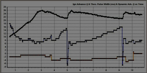
Large negative DA – Timing is removed from the DBA car (DA, yellow). Final ign timing is shown in blue and theoretical pulse width (TPW) in green. This is an excessive timing correction for a 2nd 3rd gear on power pull.
Example Data 2 – High Detonation Flag
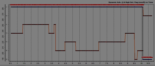
With excessive negative DA (yellow) ECU switches from normal mode (OFF) to safe mode (ONHigh Detonation Flag (red/blue - safe mode) activated – the same data from example one abo just past 10 seconds in this log.
Example 3 – Normal conditions with low dynamic advance correction (DA)
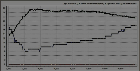
Low DA in 3rd gear high load – This is a log of a 3rd gear run showing load (theoretical pulse width (TPW), ignition timing (blue) and Dynamic Advance (DA, yellow). This “clean” pull had NO knock correction and consistent high timing. This is ideal.
Tuning Boost
COBB proportional gain boost control system has several advantages over the factory based boost control system. Boost levels can be reliably adjusted over a broad range in an RPM specific manner. Without any mechanical changes to the stock boost control system it is possible to achieve boost levels at the edge of the stock turbocharger capacity using the COBB proportional boost control coding. COBB proportional gain boost control system additionally support gear and throttle based compensations. Because the factory boost solenoid is an interrupt “3 port” style it with larger airflow capacity it will also support larger turbo and external wastegate applications.
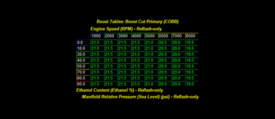
Boost Cut Primary – As with the factory boost control system the v500 and later boost control uses a boost limit table. If boost goes above this table the ECU will cut fuel to lower boost and avoid engine damage. The factory MAP sensors read to 26 psi. Setting boost cut above this level results in no effective boost cut. Higher boost pressures can be achieved using aftermarket MAP sensors such as the AMS 4 bar MAP sensor.
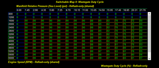
Wastegate Duty Cycle – This is the primary table used for boost control. This table is referenced by RPM on the Y-Axis and boost pressure on the X-Axis. The Z data (table data) is direct wastegate duty cycle. There is no target based feedback in this simple boost control system. At any specific RPM and boost pressure there is a referenced wastegate duty cycle. If you desire the boost to rise above this particular level the wastegate duty cycle should be high enough to promote a rise in boost pressure. In this way, wastegate duty is higher at boost levels lower than desired. At close to the desired boost level the wastegate duty cycle is reduced to produce stable boost at this level. Above target boost the wastegate duty cycle is reduced. Using the table below, observed boost pressure is 17psi in the mid range RPM. Note that at higher boost pressure wastegate duty is reduced to near zero and zero. This provides instantaneous reductions in wastegate duty cycle that very effectively avoid over boost. The key to achieving a particular boost target is determining the wastegate duty cycle that holds a specific boost target.
COBB Boost Cut - We also offer a wide variety of additional custom boost cut features. For Additional information on Barometric and Intake Air Temperature based compensations check out Cobb Custom Features: GT-R COBB Advanced Boost Control
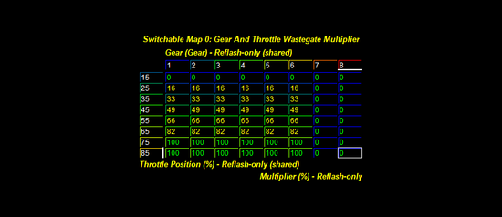
Gear and throttle wastegate multiplier – v2.01 and later GT-R calibrations use a gear and throttle position based wastegate duty cycle adjustment table. Using this table a tuner can change boost as a function of throttle position and gear. Based upon the engaged gear and throttle position the look up table specifies a percentage multiplier. This multiplier transforms the final wastegate values and thus the boost response.
For example, at 45% throttle position the final boost control solenoid duty cycle will be reduced by 50%. Over 75% throttle the boost control solenoid will run at 100% of the values in the wastegate table.
In the example below each gear produces the same relationship for boost and throttle regardless of gear.
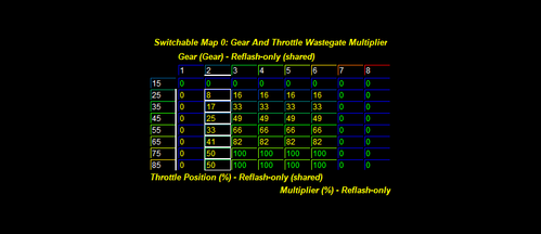
In this next example 1st and 2nd gear are programed with lower wastegate multipliers. This will allow the boost control system to produce less boost is these gears. This scenario is desirable for a road race vehicle with larger turbochargers for example where traction is limited in lower gears.
Tuning Variable Cam Timing
A single map with load engine speed axis determines the position of variable intake cams. The COBB off the shelf maps are designed slightly modified camshaft phasing optimized for stock turbochargers, stock camshafts, and stock motor internals. We have designed the COBB mapping to enhance turbo responsiveness and mid range torque. These maps may need to be altered considerably for larger turbocharger, or after market engine components. For example, care must be taken to avoid valve to valve or valve to piston contact if after market camshafts or pistons are utilized.
Integrating All Tuning Parameters for the Ideal Calibration
The ideal calibration for your GT-R is a combination of all major tuning areas outlined above. Like any performance vehicle, the GT-R will make the most power when run lean with the maximal amount of ignition timing that the ECU will allow without detonating. However, this ideal of 12.5:1 air to fuel ratio and high ignition timing is not realistic for most configurations and fuels in forced induction vehicles. The only way to determine if a calibration is ideal is to run the car on a load-based chassis dynamometer where the impact of calibration changes are easily measured. For example, addition of ignition timing that does not result in increased torque is a not ideal. If additional timing does not create power then you are simply adding stress to the engine components without tangible benefit. The same is true of boost and air to fuel ratio. If you can run the vehicle at a richer air to fuel ratio without losing power this is more ideal than running the car lean. If increasing boost does not yield considerable power gains the turbo may simply be out of its efficiency range. In this scenario less boost is actually more power. To get a coarse idea of how the ideal tune looks on your fuel type and mechanical configuration, examine the COBB OTS map notes.
Precautions
Boost – The stock turbocharger can produce boost levels in excess of 20psi. This is enough cylinder pressure to cause engine damage. Be cautious when adjusting boost control parameters. Be particularly cautious when any mechanical component of the boost control system is altered.
Injector limits – The stock fuel injectors are ~570cc. These vehicles can create enough airflow to run these injectors at or above their maximal capacity at higher RPM. This is particularly true for vehicles equipped with high flow exhaust systems and intercoolers. Be cautious about running out of injector on similarly equipped vehicles. This is particularly true in cold weather when turbocharger efficiency is high
Sensor limits – Engine control is entirely dependent upon accurate readings from the MAF sensor. Even stock vehicles produce sufficient airflow to push these sensors to their limit. Beyond the limits of the stock MAF sensor
(5.0 volts) the ECU has no way to properly control the motor. Any turbocharger upgrade must also be accompanied by an appropriate MAF sensor or intake system upgrade.
Related content
Copyright 2025 © COBB Tuning Products LLC. All Rights Reserved. | www.cobbtuning.com