Volkswagen MQB Tuning Guide


Table Descriptions and Tuning Tips 


* Disclaimer - Improper changes to your vehicle control strategy may result in engine failure *


COBB Custom Feature Guides


What is MQB?

MQB refers to a platform shared amoung many of the Volkswagen Auto Group (VAG) companies.

Modularer Querbaukasten (Modular Transverse Matrix)
The Transverse mounted front-wheel-drive or All-wheel-drive platform upon which multiple cars have been driven.  Among which COBB Offers support for:

  • MK7 GTI
  • MK7 Golf R
  • MK7.5 GTI
  • A7 Jetta GLI
  • Audi 8V S3
  • Audi 8V A3


Getting to know the MQB Platforms

Here we will go over a few of the basic details and terminologies that are specific to this platform before we begin tuning on a COBB Accessport equipped Volkswagen.

  • Airflow Pressure Based

    The Volkswagen MQB platforms utilize a MAP based airflow system. Unlike the Mk6's MAP/MAF based system, the platform is equipped with only a MAP sensor that is utilized for engine operation calculations. The VW 2.0T utilizes a manifold absolute pressure (MAP) sensor located in the intake manifold to measure the mass of air entering the engine. Changes to the intake configuration will not require tuning but heavily contaminated air filters of both OEM and aftermarket construction were found to reduce power output at moderate to high engine speeds. Frequent air filter cleaning and/or replacement is recommended for best performance and engine protection.

  • Fuel Control

    The VW 2.0T operates in a constant closed-loop state, constantly utilizing the A/F values in its tables and making adjustments via its equipped wide-band O2 sensor.

  • Boost Control

    The VW 2.0T indirectly targets boost through torque request lookup and load tables. Engine load is calculated based on numerous variables such as: pedal position, air flow, boost and RPM. Engine load is converted to a requested torque, the ECU then uses a dynamic boost level to achieve its requested torque. A diagram of the logic and calculations can be found in this document.

  • Ignition Control

    The VW 2.0T has a complex timing strategy. It allows for individual timing corrections per cylinder per event. The Accessport allows you to monitor each cylinders knock events as well as compensations for coolant temperature, intake and charge air temperature as well as other base ignition compensations. 


**After flashing a calibration to the ECU, it is not uncommon for a rough start (Aprox 15-30 sec.) as the ECU's learned adaptive's have been reset during the flash process**


The Tuning Guide

This tuning guide is divided into the basic components of tuning the VW 2.0t and the tables associated with each of these components. For each major tuning category, the guide outlines basic tuning strategies and defines tables within this category (for example: Boost Control, Fueling, and Ignition Timing). Table descriptions and tips can be found located in Accesstuner software.

What is the configuration of the vehicle?

The first step in tuning is choosing a COBB Tuning Off-The-Shelf (OTS) calibration that most closely matches the mechanical components, modifications, and fuel octane the user intends to use on the vehicle to be tuned.  To get the best idea, check our current map notes for physical part and fuel octane compatibility.

Map Notes for AP3-VLK-002

Map notes for AP3-VLK-003


Common Issues

  • While flashing the vehicle it's important that the radio doesn't attempt to connect to your phone via bluetooth as it can cause the flash to fail.
  • Walking away with the key in your pocket, or having the key battery die while flashing will cause the vehicle to turn off while flashing.
  • After a reflash of a calibration during relearn conditions, it is not uncommon for a power/boost dip to occur between 5k-6k rpm on the first pull. After the ECU has completed its learning cycle the power will return to normal. 
  • After each reflash of the calibration data and a ECU reset one will notice on initial tip-in there will be timing corrections will be present and decrement on each repetition of tip-in till they reach 0. 
  • These vehicles are relatively sensitive to charge air temperature and as such has a dedicated table like many vehicles (Final Ignition Angle Correction (IAT/CAT)) to deal with charge air increases. It is important to consider final timing when analyzing power output. 


Warnings Before You Start

  • Depending on how the COBB LC system is configured launch control may be enabled by default.  In order to turn it off you'll want to change the LC master switch to 1 which completely disables the system.
  • If the vehicle being dyno tested is equipped with Active Lane Keep (Assist) it must be disabled as unexpected steering input could result causing a loss of control on the dynamometer.  
  • The coolant temperature gauge on the dash is an inferred measurement and can raise to "overheat" conditions after multiple gear, wide open throttle runs or a single 4th gear pull in higher ambient temperature days. For actual engine temperature it is recommended to log "Coolant Temp." on the accessport or in Accesstuner. 
  • The Golf R is capable of operating in dyno roll test mode, this deactivates the AWD system and will run in FWD only mode. The Golf R uses the Haldex system, which incorporates an electro-hydraulic clutch to send power to the rear wheels. These clutch type coupling systems can generate excessive heat and wear under heavy load/long time operation on un-linked type chassis dynamometers caution is advised. 
  • Boost
    • The stock turbocharger can produce boost levels in excess of ~29 psi. This boost level can generate enough cylinder pressure to cause engine damage. Be cautious when adjusting boost control parameters. Be particularly cautious when any mechanical component of the boost control system is altered.
  • Sensor Limits
    • Engine control is entirely dependent upon accurate readings from the MAP sensor. Even stock vehicles produce sufficient airflow to push these sensors close to their limit. Beyond the limits of the stock MAP sensor the ECU has no way to properly control the engine. Any large turbocharger upgrade must also be accompanied by an appropriate MAP sensor. 
  • Clutch
    • During development it was found that power levels in excess of ~390 Ft. lbs. could cause early clutch failure. If slippage is notice it is recommend to reflash to a lower power level to avoid further damage. 


Connect the Accesstuner Software to the Accessport equipped VW 2.0t

Open the selected starting point calibration in the Accesstuner software. Configure the Accesstuner software to connect to your vehicle. Attach the OBDII cable to the vehicle and the associated USB to the computer and Accessport. Press "Ctrl+F" to configure the program. Select the directory in which to store your data logs under the "logging" tab. 


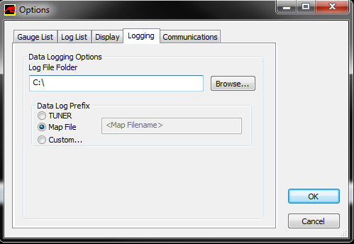
Display and Log critical engine parameters while testing


Accesstuner software allows the user to visualize, sample and record critical engine parameters including sensor information and commanded engine function.
To setup displayed parameters on the live "Dashboard" press "Ctrl+F" to configure the logged parameters in the "Log List" tab, and those displayed in the Accesstuner "Dashboard" through the "Gauge List" tab. The Dashboard, a screen that reports active engine and sensor parameters, can be accessed by pressing "Ctrl+B." It is critical to actively monitor the condition of the motor during tuning and this screen is the single best way to do so. These data monitors allow the tuner to determine if a calibration is performing correctly. Accurate and deliberate assessment of logged parameters is the only way to avoid conditions that may damage the motor.

For a complete list of available monitors and their definitions, check out our article Engine Monitor List for Volkswagen & Audi MQB Vehicles


Calibration Refinement (Using a Load-Based Chassis Dynamometer)

Perform initial testing at lower boost

After choosing the most appropriate starting point calibration, prepare to test and refine the calibration on a load-based chassis dynamometer. When creating a custom tune, it is best to begin testing under low load (boost) conditions by lowering values in the  "PUT Setpoint" table as well as the corresponding "Mass Air Set Point for Torque Intervention" and/or "Maximum Torque Manual/Automatic" tables. This lowers the requested load (boost). Testing done at lower boost will allow you to assess the calibration without putting the motor under potentially dangerous conditions. Start the tuning process by loading this "low boost" starting point calibration onto the vehicle. 

Increasing airflow/torque target to attain greater boost

The Volkswagen 2.0t is a "Torque/Airflow Target" based system, meaning it uses a complex routine to reference multiple tables based on conditions (Barometric pressure, Atmospheric Temp, Current Knock Condition, Coolant Temp, Charge Air Temp. EGR, Turbine flow Etc.) to achieve its target load/airflow.

There are many limits and targets surrounding load/airflow and these are what are typically manipulated in order increase HP and TRQ. The main control for the boost system is the "Maximum Torque Manual/Automatic" tables. These tables are the X axis reference for the requested airflow which is derived from "Mass Air Setpoint for Torque Intervention" tables. Raising the requested torque in "Maximum Torque Manual/Automatic" will increase the requested mass air flow per stroke (Z table data) thus raising the calculated boost target from the "PUT Setpoint" table. The maximum boost pressure and request is calculated from the "PUT Setpoint" table. This table is referenced from by calculation derived from the "Mass Air Setpoint for Torque Intervention". The data from "Mass Air Setpoint for Torque Intervention" is used as the X axis lookup. It is important to keep the X axis and the Z data consistent on the "PUT Setpoint" in order to keep the system operating properly. (See OTS data for examples)

Golf R

Boost control logic in the Golf R remains much the same with the exception of the PUT setpoint acting as a ceiling, all boost calculations are derived from the base "Mass Air Setpoint for Torque Intervention". Manipulating the data in these tables along with the "Maximum Torque Manual/Automatic" will allow for greater boost set point calculations. Logging "Boost Pressure" and "trgt. Boost Pressure" will allow you to see where the system is targeting boost. Logging "Engine Speed"(Y Axis) and "Driver Requested Torque"(X Axis) will show where adjustments can be made to manipulate the final boost request.

See: BOOST/WGDC system for more detail and logic flow chart.

In order to gain understating of the ECU's current operation we should monitor "Air Mass Intake Manifold per Stroke" (to determine actual engine load) as well as all relevant torque and turbo speed monitors to assure we are within the requested limits.

An important thing to understand is the ECU will run the lowest load/trq/limit being requested or limited to.


Even without any mechanical changes to the stock boost control system it is possible to achieve boost levels at the edge of the stock turbocharger capacity. At sea level, aggressive tuning using the stock boost control system can achieve 29+ psi mid-range and more than 24 psi at redline.
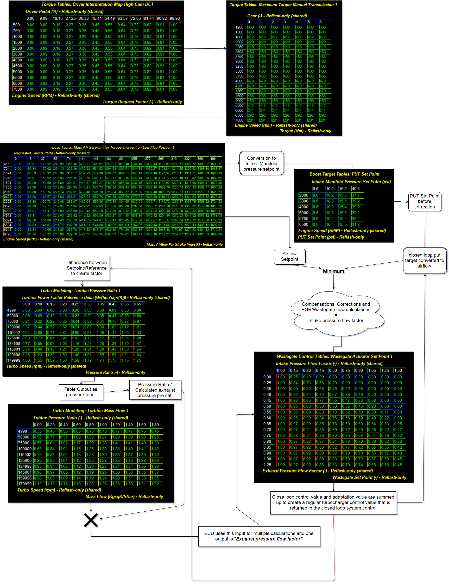


Boost / WGDC System

The ECU uses a target Airflow/Pressure/Trq based boost system to try and control boost before the throttle plate. This table is called Pressure Up Throttle Setpoint. This is a target boost pressure and should be raised if you are trying to increase the boost pressure. On the Golf R this table is simply referenced as a ceiling, allowing all adjustments to be made in the torque request and Mass air setpoint tables. The target pressure can be logged, and should be when trying to increase boost pressure. The boost pressure cannot be raised if the Maximum Airflow tables ("Mass Air Set Point for Torque Intervention") are not high enough! If you increase the PUT tables and the boost does not increase it is more than likely due to the Maximum Airflow tables not being high enough.

The Volkswagen 2.0t also uses an estimated turbo speed setpoint. Although the car does not have actual turbo speed sensors on the compressor of the turbo, it uses a calculation to estimate the turbo speed. In order to raise target boost pressure you will need to raise the max limits of the turbo speed tables in order not to trigger any errors.

The Volkswagen 2.0t uses an algorithmic base to calculate the wastegate actuator position using a number of modeled airflow lookups as well as atmospheric and conditional inputs The vehicle is not equiped with a traditional WG solenoid system, it is equiped with an electrically actuated wastegate. The main tables for the end control of the positions are "Wastegate Actuator Setpoint 0 and Wastegate Actuator Setpoint 1" Below you will find high level overview to help visualize the logic flow of the boost control system and calculations:          


Tuning for appropriate Air to Fuel ratios

The Volkswagen 2.0t utilizes direct injection versus conventional port injection in its turbocharged engines. In direct injection the gasoline is highly pressurized, and injected via a common rail fuel line directly into the combustion chamber of each cylinder, as opposed to conventional multi-point fuel injection that happens in the intake plenum, or cylinder port. This gives the Volkswagen 2.0t many advantages for improved fuel efficiency under light load conditions, and also allowing a leaner Air/Fuel ratio.  The major advantages of the direct injection engine are increased fuel efficiency and higher power output. Gains are achieved by the precise control over the amount of fuel and injection timings that are varied according to the load condition

The ideal air to fuel ratio depends upon fuel quality. Higher octane fuels are more detonation resistant and therefore can be run at leaner air to fuel ratios. Leaner Air to Fuel ratios produce higher power but also create more heat. Excessive heat can lead to detonation. Lower octane fuels such as 91 octane or 95 RON are more prone to detonation and therefor require a richer air to fuel ratio. Rich air to fuel ratio combustion produces less heat and therefore less detonation. Several tables directly impact fueling ratios in these cars. While not in catalyst/turbo protection "Lambda Set Point Airflow Based", "Lambda at Full Load / High IATand "Lambda Basic HDPI Set Point" are the primary tables dictating fuel mixtures.The tables are used by the ECU to set the desired AFR while not in a catalyst/turbo protection state. While the car attempts to control catalyst temperatures it will reference "Lambda Value for Overheat Prevention", "Minimum Value for Catalyst Overheat Protectionand "Minimum Value for Turbo Overheat Protection".

The VW 2.0t utilizes internal wide-band oxygen sensors to monitor fuel mixtures. The sensor is located in the turbo manifold and down pipe. As a result, the values in the fuel tables are a closed loop target that the ECU will always work to achieve. The active adjustments made by the ECU are displayed in the "Lambda" monitor.


Fuel Injection Scaling and Strategy

2015 and 2016 GTI use a different strategy than the other cars which COBB currently supports in the VW platform. The roms affected are 5G0906259A and 5G0906259D. These roms use 'Injection Time (High, Low, Over) Pressure' maps to convert the Mass Fuel Flow Set Point into an injection time. The 2017+ GTI and ALL of the Golf R roms use 'Effective Injection Time (High, Low, Mid) Temperature' maps. The Mass Fuel Flow Set Point is not mapped out as far as the latter version and will need to be rescaled once you start reaching fuel injection times in the 6.5ms range. Fuel Stoich Point is a quick and correct way to scale the fuel system if using fuel with added ethanol content. Information on correctly scaling it is available in the Table Description. 


Tuning for appropriate Spark Advance 


Ignition timing tables 

The main tables for ignition timing at WOT are "Ignition Timing Port Flaps Low". Main timing tables for light load and cruise are "Ignition Timing Port Flaps High"These tables are referenced by "Airflow per stroke" and "Engine speed". Logging "Air mass intake manifold per stroke" and "Engine Speed" will allow you to reference the specific regions of these tables that may need to be edited to produce optimized ignition timing.

The ECU will calculate base ignition from "Ignition Timing Port Flaps Low" under normal full load conditions. However, due to sensitivity to hot charge air temperatures large reductions can be made to the base ignition request. Referencing "Final Ignition Angle Correction IAT" will allow manipulation of corrections depending on IAT conditions. 


Final Ignition Angle Correction CAT / IAT - CAT / IAT source bit switch

Final ignition timing is corrected for charge air or intake air temperature via the "Final Ignition Angle Correction IAT/CAT" table. The input to the x axis can be altered by the "Switch for Charge Air Source" bit located in the Miscellaneous Tables folder. When this value is set to 0 it will utilize the IAT (T-Map sensor) as the input while when the bit is set to 1 (stock setting) it will utilize the modeled CAT via ECU calculations. 

Timing adjustments are currently limited to ~.38 degree increments. 


Detonation based timing adjustment

Ignition timing is also adjusted in response to detonation or pre-ignition. The ECU actively reduces timing in response to detonation. The ECU has the capability to make individual cylinder timing adjustments, because of this monitoring a single cylinders timing correction will not result a global picture of engine operations. Timing adjustments in response to detonation are logged with the "Knock Retard 1-4." monitors. Each knock event results in a change of ~.38 degree increments depending on severity of the event.
Generally speaking, higher ignition timing supports higher torque and greater power. However, ignition timing should be increased with great caution. Higher timing yields higher cylinder pressures and this is limited by fuel quality and the mechanical limitations of the engine. Too much timing will produce knock correction when fuel quality is limiting. When fuel quality is high, ignition timing should ONLY be added when its addition produces a substantive increase in torque and power. If increased timing does not increase torque the extra cylinder pressure is simply producing unnecessary stress on engine components.


Ignition Angle Correction Combustion mode 0-7

These base tables will be applied to the final ignition calculation depending on the current combustion state. This state can be monitored by selecting the Combustion Mode monitor and logging its output. 


Tumble Flaps

The VW 2.0T is equipped with tumble flaps that are individual plates located within the intake manifold runners that can either stay in a flat position to allow maximum airflow or move up to redirect the airflow into the combustion chamber. At
different engine rpms, the tumble flaps are activated to enhance the air/fuel mixture.

The tumble flaps are actuated:
• To improve cold engine idling
• To improve charge efficiency at start-up
• In overrun mode

At other engine speeds, the tumble flaps are open to eliminate flow resistance and reduction in engine performance.

Tumble flap adjustments can be found in the "Miscellaneous Tables" folder. 


Integrating all tuning parameters for the ideal Calibration

The ideal calibration for your VW 2.0t is a combination of all major tuning areas outlined above. Like any performance vehicle, the VW 2.0t will make the most power when run lean with the maximum amount of ignition timing that the ECU will allow without detonating. However, this ideal of 12.5:1 air to fuel ratio and high ignition timing is not realistic for most configurations and fuels in forced induction vehicles. The only way to determine if a calibration is ideal is to run the car on a load-based chassis dynamometer where the impact of calibration changes is easily measured. For example, addition of ignition timing that does not result in increased torque is a not ideal. If additional timing does not create power then you are simply adding stress to the engine components without tangible benefit. The same is true of boost and air to fuel ratio. If you can run the vehicle at a richer air to fuel ratio without losing power this is more ideal than running the car lean. If increasing boost does not yield considerable power gains the turbo may simply be out of its efficiency range. In this scenario less boost may produce more power. To get a coarse idea of how the ideal tune looks on your fuel type and mechanical configuration, examine the COBB OTS maps and map notes.


Copyright 2023 © COBB Tuning Products LLC. All Rights Reserved. | www.cobbtuning.com