BMW N55 Tuning Guide
- Brandyn Mowat
Analytics

BMW N55 Tuning Guide
Getting to know the BMW N55
Here we will go over a few of the basic details and terminologies that are specific to BMW before we begin tuning on a COBB ACCESSPORT equipped BMW N55.
MAP Based – The N55 primarily uses a MAP based airflow system, this is also known as Speed Density. Unlike the N54, the N55 is also equipped with a MAF sensor that is utilized in parts of the DME logic, mostly for WGDC/Boost control. The BMW N55 utilizes manifold absolute pressure (MAP) sensors located pre and post throttle body to measure the mass of air entering the engine. Filter configuration does not necessarily require tuning but heavily contaminated air filters of both OEM and aftermarket construction were found to reduce power output at moderate to high engine speeds. Frequent air filter cleaning and/or replacement is recommended for best performance and engine protection.
Throttle Closures – The primary method of controlling boost on this car is done with the assistance of the drive-by-wire throttle system. The factory tune allows the throttle to close to less than 20% (of the ~100% max) which can result in consistent torque delivery, but reduced performance. There are two main offenders that will result in throttle closures: overshoots of load and boost. Major throttle closures can result in turbulent airflow entering the cylinders causing timing corrections. It is imperative when analyzing logs to assure no throttle closures are present during a timing correction event as these could create a false positive. We recommend adjusting these limits higher to take full control of the throttle and keep closures to a minimum. See our OTS maps for effective examples.
Fuel Control – The N55 operates in a constant closed-loop state, constantly utilizing the A/F values in its tables and making adjustments via its equipped wide-band O2 sensors. The fueling is split into two tables, bank 1 (front three cylinders) and bank 2 (rear three cylinders). It is important to assure that both tables have identical changes to assure both banks are fueling correctly.
Boost Control – The N55 does not directly target boost, but rather engine load. Engine load is calculated based on numerous variables such as: pedal position, air flow, boost and RPM. Engine load is converted to a requested torque, the DME then uses a dynamic boost level to achieve its requested torque.
Ignition Control – The BMW DME has an incredibly complex timing strategy. It allows for individual timing corrections per cylinder per event. It also allows the vehicle to add timing during cruise conditions while “listening” to the knock control system to maximize efficiency and economy. Small timing corrections during cruise/light throttle are normal and to be expected.
Traction Control Events – One strategy the BMW DME uses to control traction events is to reduce power. To reduce power the DME pulls boost, manipulates the throttle plate and alters fueling. During dynamometer testing it was observed the vehicle maintaining a 14.7 AFR throughout the entire power pull. It is important to completely disable (hold DSC button) the traction control system during tuning or logging in order to gather reliable data.
The Tuning Guide
This tuning guide is broken into the basic components of tuning the BMW N55 and the tables associated with each of these components. For each major tuning category, the guide outlines basic tuning strategies and defines tables within this category (for example: Boost Control, Fueling, and Ignition Timing). Table descriptions and tips will follow the basic tuning strategies below.
Step 1 – What is the mechanical configuration of the vehicle?
The first step in tuning a BMW N55 is choosing a COBB Tuning Off-The-Shelf (OTS) calibration that most closely matches the mechanical components and modifications of the vehicle to be tuned.
The Stage1 calibrations are designed for vehicles with a stock or axle-back exhaust system. The Stage1 COBB mapping was designed with optimized ignition, boost, and fuel targets for enhanced performance and responsiveness on a vehicle with mainly stock hardware.
The Stage1+FMIC calibrations are designed for vehicles equipped with upgraded FMIC with a stock or axle-back exhaust system. The Stage1+FMIC COBB mapping was designed with optimized ignition, boost, and fuel targets for enhanced performance and responsiveness on vehicles with upgraded FMIC hardware.
The Stage2 mapping is designed for vehicles equipped with high flow down pipes. Additional performance can be obtained by fitting a cat back exhaust which replaces the restrictive factory mufflers as well as an upgraded intake system (DCI, Panel filter or similar).
The Stage2+FMIC mapping is designed for vehicles equipped with an upgraded front mount inter-cooler, full turbo back exhaust and an upgraded intake system. The COBB Stage2+FMIC mapping was designed with optimized ignition, boost, and fuel targets for enhanced performance and responsiveness for vehicles equipped with “FBO”.
Step 2 – What fuel is the vehicle using?
Please note that COBB Tuning offers calibrations for three different fuels: Aggressive: 93 octane (98 RON), Sport: 91 octane (95 RON) and ACN91 (91 octane from Arizona, California, or Nevada). If your fuel does not meet the standard of the available COBB maps you will need to adjust the calibration accordingly. Take a moment to compare and contrast timing, boost, and ignition tables from each type of calibration. Higher octane fuels support more ignition timing, higher boost levels, and leaner air to fuel mixtures compared to lower octane. Using a map designed for high-octane with low-octane fuels can produce engine damage.
Step 3 – What type of air intake is on the vehicle?
The BMW N55 utilizes manifold absolute pressure (MAP) sensors located pre and post throttle body to measure the mass of air entering the engine. Filter configuration does not necessarily require tuning but heavily contaminated air filters of both OEM and aftermarket construction were found to reduce power output at moderate to high engine speeds. Frequent air filter cleaning and/or replacement is recommended for best performance and engine protection.
Preparing to calibrate the vehicle
Connect Accesstuner Software to Accessport Equipped Vehicle
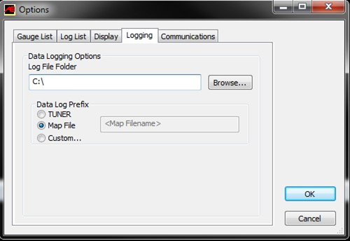
Open the selected starting point calibration in the ACCESSTUNER software. Configure the
ACCESSTUNER software to connect to your vehicle. Attach the OBDII cable to the vehicle and the associated USB to the computer and ACCESSPORT. Press “Ctrl+F” to configure the program. Select the directory in which to store your data logs under the “logging” tab.
Display and Log Critical Engine Parameters
ACCESSTUNER software allows the user to visualize, sample and record critical engine parameters including sensor information and commanded engine function.
To setup displayed parameters on the live “Dashboard” press “Ctrl+F” to configure the logged parameters in the “Log List” tab, and those displayed in the ACCESSTUNER “Dashboard” through the “Gauge List” tab. The Dashboard, a screen that reports active engine and sensor parameters, can be accessed by pressing “Ctrl+B.” It is critical to actively monitor the condition of the motor during tuning and this screen is the single best way to do so. These data monitors allow the tuner to determine if a calibration is performing correctly. Accurate and deliberate assessment of logged parameters is the only way to avoid conditions that may damage the motor.
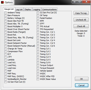
While connected to a running behicle, go into configure options and the log list tab in order to select the parameters saved to Accesstuner Datalogs. When datalogging is enabled these parameters will be permanently written to a comma delimited (CSV) data file.
More than 22 parameters can be selected at any time however the rate of data collection will go down. For example you will see a higher rate with 12 parameters than 20.
Pedal Position – The percent of pedal movement at the driver’s foot.
TPS Actual –This is the final actual throttle angle including all compensations and trims.
Lambda– The lambda reading taken from the internal wide-band oxygen sensor (Front).
MAF Req. (WGDC) – The amount of air moving through the engine in reference to the WGDC system. Boost Rel. – Boost as measured in relative form, this is measured pre-throttle body
Boost Readings
It is important to remember when analyzing boost pressure data that the reading is taken in front of the (pre) throttle blade and any closures can cause an inaccurate reading of actual manifold pressure. This is due to a buildup of pressure in the charge pipe before the throttle plate during a closure event.
Boost Pressure Abs. – Boost as measured in absolute form.
Boost Request Abs. – Boost as requested by the DME in absolute form.
Boost Set point Factor – Boost pressure set point factor utilized by WGDC system.
Charge Air Temp. – (CAT) Charge air temperature as measured post intercooler, before the throttle body.
Coolant Temperature – Engine coolant temperature.
Engine Speed / RPM– Engine speed in revolutions per minute (RPM).
Ignition Timing Corr. Cyl. (1-6) – Individual cylinder timing correction in degrees (+/-).
Timing Corrections
Negative timing corrections should remain as minimal as possible, with that said small negative timing corrections are a part of the N55’s elaborate ignition control strategy. When logging all cylinders corrections under full throttle, consistent negative corrections across multiple cylinders or incremental corrections indicate excessive engine noise and is a sign that the map might be too aggressive for the mechanical condition of your vehicle.
Ignition Timing Cyl. (1-6) – This is the final actual ignition timing after all correction and adjustments in degrees before TDC.
Load Requested – This is the DME’s requested calculated engine load value. Load Actual – This is actual calculated engine load value.
WGDC Base – This is the base wastegate solenoid duty cycle before PID system compensations.
WGDC after PID – This is the final wastegate solenoid duty cycle after PID system compensations. STFT – Short term fuel trims displayed in percent. (See LTFT for description) LTFT – Long term fuel trims displayed in percent.
Fuel trims refer to adjustments being made by the DME dynamically to the base fuel table to get the proper air fuel ratio. Short term fuel trim refers to adjustments being made in response to temporary conditions. Long term fuel trims are used to compensate for issues that seem to be present over a longer period. Fuel trims are expressed in percentages; a positive value indicates lean (DME is adding fuel) and negative values indicate rich (DME is subtracting fuel). On the N55 Fuel trim banks refer to the 3 cylinder banks front and rear. Fuel trims are generally calculated by using a wide set of data values, including pre-cat O2 sensors, intake air
temperature/pressure, ECT, knock sensors, engine load, throttle position, and even battery voltage can effect fuel trim. Long term fuel trims generally should not exceed +- 10%, while short term trims at idle should be in the +- 3% range. The N55 has the ability to adjust up to +- 34%.
Stock Calibration usage:
Due to a DME logic change that is required to allow correct load request calculations, any calibration used (other than uninstalled) will have altered load requests thus causing higher power/load requests than true stock (uninstalled). You will notice that starting with v200 mapping we no longer offer a Stage0 map due to this DME logic change. In order to acquire true “Stock” baseline data we recommend performing dynamometer testing in uninstalled stock state prior to beginning tuning/testing.
Calibration Refinement (Using a Load-Based Chassis Dynamometer)
Perform initial testing at lower boost
After choosing the most appropriate starting point calibration, prepare to test and refine the calibration on a load-based chassis dynamometer. When creating a custom tune, it is best to begin testing under low load (boost) conditions by lowering values in the “Load Ceiling (Main), Modeled Torque Limit or Torque Request Ceiling” tables. This lowers the requested load (boost). Testing done at lower boost will allow you to assess the calibration without putting the motor under potentially dangerous conditions. Start the tuning process by loading this “low boost” starting point calibration onto the vehicle.
Increasing load target to attain greater boost
The BMW N55 DME is “Load Target” based, meaning it uses a complex routine to reference multiple tables based on conditions (Barometric pressure, Atmospheric Temp, Current Knock Condition, Coolant Temp, Charge Air Temp. Etc.) to achieve its target load utilizing a dynamic boost level.
There are many limits and targets surrounding load and these are what are typically manipulated in order increase HP and TQ. The main control for the boost system is the “Load and Torque Ceiling” tables. We will raise these values to increase boost as we begin tuning. We will utilize the WGDC parameters to keep the system “in-check” rather than use it to control boost like some other systems. The WGDC system on the BMW is PID controlled, making large or incorrect adjustments can upset the system causing throttle closures (over-boost) or under-boosting.
In order to gain understating of the DME’s current operation we should monitor “Load Act.” (to determine actual engine load), and “Load Req.” (to determine what the ECU is targeting). The DME will not always hit its load target ceiling, so some deviation between “Load Req.” and “Load Act.” is not uncommon or necessarily sign of problems.
An important thing to understand is the DME will run the lowest load being requested or limited, also, these load values are a ceiling not a true “target”.
The turbocharger boost levels are the main variable used to create torque. When you increase your load targets, you will see the ECU uses more Waste-gate Duty (%) in order to achieve the higher torque (boost) levels. Increasing load target values will allow the vehicle to create more boost (within the systems limits) as long as the limit tables are raised.
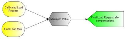
Load Control/Request Logic Diagram
To create the desired load request please reference the load logic diagram below:
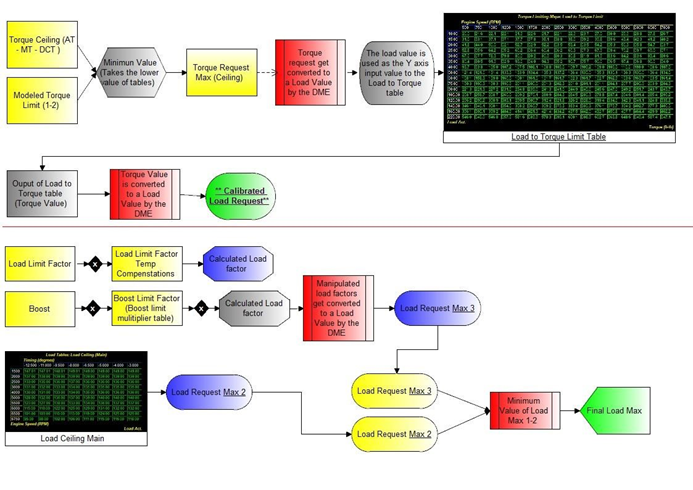
Without any mechanical changes to the stock boost control system it is possible to achieve boost levels at the edge of the stock turbocharger capacity. At sea level, aggressive tuning using the stock boost control system can achieve 21.5+ psi midrange and more than 14psi at redline.
WGDC System and Adjustments

Wastegate Duty Cycle (Base)
This is the primary table the DME uses for boost control. This table is referenced by “Boost Setpoint Factor” on the Y-Axis and “MAF (WGDC)” on the X-Axis. The Z data (table data) is direct wastegate duty cycle %. These are starting WGDC numbers before the boost control systems PID’s kick in and control boost. Adjusting the main table is mostly used for load targeting corrections, adding or removing small amounts to correct “boost error”. Correcting boost error will also remove most throttle closures. Adding more wastegate than the system deems necessary will result in the system making corrections and can cause major throttle closures.
Throttle Closures:
Throttle closures are a result of the DME reading a higher “Boost Absolute” or “Load Act.” than it has requested. These throttle closures can be seen in the log as a deviation between the “Pedal Position” value and “TPS actual”. “Pedal Position” should read ~%99.61 when at wide open throttle and “TPS Actual” should read ~%99. Lower “WGDC base” in these areas to reduce overshoots. We will discuss how to correctly identify these areas in the next section.
To Adjust/Monitor WGDC performance:
Add “Boost Setpoint Factor” and “MAF Req. (WGDC)” to your logging. These are the axis for the “WGDC (base)” table that we will be adjusting. If needed remove other unused monitors from your logs to make room. Once these monitors are added, collect a log where throttle closures can be seen.
Next step will be to open AccessTUNER and adjust the WGDC (Base) table in the affected area. You should have the required data in the logs to make these changes. The X axis for the table is “MAF Req. (WGDC)” and the y axis is “Boost Setpoint Factor”.
Now, look in your logs and find where Actual Load surpasses Load Requested. Once you find the problem area, look at the corresponding values for the X and Y axis on the “WGDC(Base)” table and that's where you'll be making your changes. Find the cell that matches, and highlight adjacent cells as well (the DME will "blend" several cells to get final values). You're going to want to lower the values in the problem area to correct throttle areas, or raise them to correct under-boost/under-load. Make small incremental changes to the base table then re-flash and re-log.
*Note: Starting from different gears and RPM will change the sweep of the curves and will take some fine tuning to achieve a smooth boost curve for all gears and starting points.
Tuning for appropriate Air to Fuel ratios
The ideal air to fuel ratio depends upon fuel quality. Higher octane fuels are more detonation resistant and therefore can be run at leaner air to fuel ratios. Leaner Air to Fuel ratios produce higher power but also create more heat. Excessive heat can lead to detonation. Lower octane fuels such as 91 octane or 95 RON are more prone to detonation and therefor require a richer air to fuel ratio. Rich air to fuel ratio combustion produces less heat and therefore less detonation.
Several tables directly impact fueling ratios in these cars. Fuel (Bank 1) Fuel (Bank 2) are the primary tables dictating fuel mixtures The DME also uses Fuel (Spool) for a short period during its
“spool” mode.
These tables are referenced by Load and Engine speed. These are target tables; they are used by the DME to set the desired AFR.
The BMW N55 utilizes internal wide-band oxygen sensors to monitor fuel mixtures. The sensors are located in the down pipe. As a result, the values in Fuel (Bank 1) and Fuel (Bank 2) are a closed loop target that the DME will always work to achieve. The active adjustments made by the DME are displayed in the “Lambda” monitor.
Tuning for Appropriate Spark Advance
Ignition timing tables - The main table for ignition timing is Timing (Main); Timing (Spool) is used for a brief period while DME works to build boost with minimal lag. These tables are referenced by “Load” and “Engine speed”. Logging these parameters will allow you to reference the specific regions of these tables that may need to be edited to produce optimized ignition timing.
Detonation based timing adjustment - Ignition timing is also adjusted in response to detonation or pre-ignition. The DME actively reduces timing in response to detonation. The DME has the capability to make individual cylinder timing adjustments, because of this monitoring a single cylinders timing correction will not result a global picture of engine operations. Timing adjustments in response to detonation are logged with the “Cyl 1-6 Timing Cor.” monitor. Each knock event results in a change of .5 degree increments depending on severity of the event.
Generally speaking, higher ignition timing supports higher torque and greater power. However, ignition timing should be increased with great caution. Higher timing yields higher cylinder pressures and this is limited by fuel quality and the mechanical limitations of the engine. Too much timing will produce knock correction when fuel quality is limiting. When fuel quality is high, ignition timing should ONLY be added when its addition produces a substantive increase in torque and power. If increased timing does not increase torque the extra cylinder pressure is simply producing unnecessary stress on engine components.
Integrating All Tuning Parameters for an Ideal Calibration
The ideal calibration for your BMW N55 is a combination of all major tuning areas outlined above. Like any performance vehicle, the N55 will make the most power when run lean with the maximum amount of ignition timing that the ECU will allow without detonating. However, this ideal of 12.5:1 air to fuel ratio and high ignition timing is not realistic for most configurations and fuels in forced induction vehicles. The only way to determine if a calibration is ideal is to run the car on a load-based chassis dynamometer where the impact of calibration changes is easily measured. For example, addition of ignition timing that does not result in increased torque is a not ideal. If additional timing does not create power then you are simply adding stress to the engine components without tangible benefit. The same is true of boost and air to fuel ratio. If you can run the vehicle at a richer air to fuel ratio without losing power this is more ideal than running the car lean. If increasing boost does not yield considerable power gains the turbo may simply be out of its efficiency range. In this scenario less boost may produce more power. To get a coarse idea of how the ideal tune looks on your fuel type and mechanical configuration, examine the COBB OTS maps and map notes.
Precautions
Boost
The stock turbocharger can produce boost levels in excess of 25psi. This boost level can generate enough cylinder pressure to cause engine damage. Be cautious when adjusting boost control parameters. Be particularly cautious when any mechanical component of the boost control system is altered.
Sensor Limits
Engine control is entirely dependent upon accurate readings from the MAP sensor. Even stock vehicles produce sufficient airflow to push these sensors to their limit. Beyond the limits of the stock MAP sensor (4.67 volts – 2.5 bar) the ECU has no way to properly control the motor. Any turbocharger upgrade must also be accompanied by an appropriate MAP sensor.
Tuning Tips
Boost Control Tables
Boost Ceiling –This is the maximum positive pressure (boost) the DME will allow for boost control.
Tuning Tips - Raising this value can be used to help when using the commanded WDGC / Commanded Boost Target. Manipulating these values when not in commanded mode can cause the system to become unstable.
Boost Limit Multiplier Ceiling – This is the DME’s ceiling for the Boost Set Limit (Multiplier).
Tuning Tips - Raising this value can be used to help when using the commanded WDGC / Commanded Boost Target. Manipulating this value when not in commanded mode can cause the system to become unstable.
Boost Multiplier – This table is used as a multiplier for boost request.
Tuning Tips – Raising this table can cause the DME to throw over-boost and torque calculation errors. The output of this table can be viewed by logging the boost set limit monitor.
Commanded Boost Switch – This switch must be set to one (1) to utilize the “Commanded Boost”
Tuning Tips – Setting this value to 1 activates commanded boost logic (Commanded WGDC Table).
Commanded Boost Target – Commanded Boost Logic, Boost Pressure Request. This will force the DME to try to run a particular boost target. – This value is used in conjunction with “Commanded WGDC Table”.
Tuning Tips – This is the commanded boost value. This will require extensive tuning and testing to create a map with good part throttle drivability.
Pressure Drop Over IC – This is the modeled Pressure drop across the stock intercooler.
Tuning Tips – Manipulating this can alter final load request. This table allows for calibrated corrections for known intercoolers.
Sub-Folder WGDC Tables
Commanded WGDC Table – This Table allows a commanded WGDC position to be used much like conventional boost control systems. This table requires the “Commanded WGDC Switch” value to be set to 1.
Tuning Tips – This table allows a tuner to set a manual wastegate value. The system still maintains some level of compensation (Altitude, temp, P.I.D. Etc.)
Commanded WGDC Switch –This switch must be set to one (1) to utilize the “Commanded WGDC Table”
Tuning Tips – See “Commanded WGDC Table”
WGDC Base –This is the base starting point for WGDC in the normal boost control system (Non-Commanded Waste Gate). This table is used to manipulate load requests to match load requests if the system is over or under target.
Tuning Tips – See “WGDC System Adjustments”
WGDC Spool–This is the base starting point for WGDC during initial tip-in (Spool Mode) in the normal boost control system (Non-Commanded Waste Gate). This table is used to manipulate load requests to match load requests if the system is over or under target.
Tuning Tips – See “WGDC System Adjustments”
WGDC Airflow (Adder) – These values allow the system to add to the base WGDC system values based on MAF.
Tuning Tips – If more WGDC is desired at a set M.A.F. these values can be raised to increase base WGDC.
WGDC Ceiling (Adder) – These values allow the system to add to the base WGDC Ceiling based on MAF.
Tuning Tips – Raising this value will allow the system to achieve a higher final WGDC.
WGDC P/I/D-Factor – P/I/D-Factor used in the WGDC PID calculations.
Tuning Tips – This table can be manipulated (most the time lowering) to correct/compensate for boost/WGDC oscillations.
Fuel Tables
Fuel (Bank 1-2) – Main Tables used for closed loop fueling targets.
Tuning Tips – Main fuel tables. Also see “Fuel Injection System” at end of this document for a brief description of direct injection.
Fuel (Spool) - Used in conjunction with other spool tables.
Tuning Tips – This table is used during initial spool mode to help the system build boost and reduce lag.
Fuel Scalar – Table/Value used to adjust for alternative fuels.
Tuning Tips – This table/value is used to correct fuel trims for alternative fuels. (ex. E- 85)
Ignition Tables
Timing (Main) – This is the Main Ignition Table.
Tuning Tips - None at this time.
Timing (Spool) – This Table is used in conjunction with other “Spool mode” tables to help the system build boost while reducing lag.
Tuning Tips - None at this time.
Limit Tables
Boost Limit Multiplier – This table is referenced by the DME to calculate its ceiling for boots control.
Tuning Tips – Raise this table to help the system maintain correct boost control. The output of this calculation can be monitored by logging “Boost Set limit”
Load Difference Ceiling– Allowable difference between actual and requested load.
Tuning Tips – Raising this table could help the system maintain correct boost/load control calculations.
Load Limit Factor – Multiplier used for load calculation.
Tuning Tips – None at this time.
Load Limiting Factor (ECT) – Multiplier used to limit load based on ECT temps.
Tuning Tips – None at this time.
Load Limiting Factor (IAT) – Multiplier used to limit load based on IAT temps
Tuning Tips – None at this time.
Load to Torque Multiplier –This table is multiplied against the result of the Load to Torque Limit table.
Tuning Tips – None at this time.
Sub-Folder: Torque Limiting Maps
Load to Torque Limit – Used for the DME’s conversion of Load to Torque.
Tuning Tips – None at this time.
Torque EFF Divisor (FUEL) – Used as a multiplier to manipulate torque requests based on AFR.
Tuning Tips – Altering this will\can effect load calculations.
Torque Reduction Factor (RPM) – Used to limit torque based on RPM.
Tuning Tips – None at this time.
Torque Reduction Factor (TEMP) – Used to limit torque output based on Oil temp and ECT.
Tuning Tips – None at this time.
Load Tables
Load Ceiling (MAIN) – In the OTS mapping strategy this is the primary table for load request ceiling
Tuning Tips – The X Axis is Timing Correction in degrees BTC, as the DME corrects for ignition events it also has the ability to remove load as the events increase. Use the “-3” deg. column for “normal” operation mode. We recommend tapering the load request as timing corrections increase.
Load Target Offset (Over-Boost) – This table is used for over-boost control in models with this feature
Tuning Tips – None at this time.
Modeled Torque Limit 1-2 – This is the secondary load request table in OTS strategy.
Tuning Tips – The X axis is referenced by “Gear”, this allows for individual load request by gear.
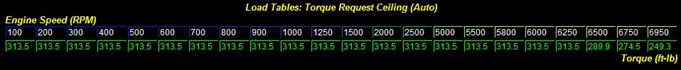
Torque Request Ceiling (AUTO – DCT – MANUAL) – This is the third load/torque request table in the OTS Mapping.
Tuning Tips – These tables allow for individual request via transmission types.
Throttle Tables
Threshold (Major Throttle Closures) –
Tuning Tips – Raising these values closer to 1.0 will dampen the DME’s throttle plate adjustments during throttle closures and overshoots.
Throttle Angle Aggression in Over Load –
Tuning Tips – Changing the first column 0.000’s along the Y data (0.000 Boost Over-Shoot Factor value row) can result in undesired throttle plate behavior. Monitoring “Actual TPS” will allow you to watch changes to this table.
Torque Request Tables
Requested Torque (AUTO) – Allows throttle input to torque request to be adjusted on automatic vehicles.
Tuning Tips – Raising the Z data in this table will raise the requested torque by the DME, lowering will do the inverse.
Requested Torque (MANUAL/DCT) – Allows throttle input to torque request to be adjusted on manual/DCT vehicles.
Tuning Tips – Raising the Z data in this table will raise the requested torque by the DME, lowering will do the inverse.
Diagnostic Trouble Codes
Press “Ctrl-A” to bring up the Advanced Engine Parameters window. You will be able to enable and
disable select DTC’s by changing the corresponding checkbox for each. A box with a check will indicate the DTC is active and in-use. A re-flash of the ECU is necessary to invoke these changes.
Fuel Injection System
The N55 utilizes direct injection versus conventional port injection in its turbocharged engines. In direct injection the gasoline is highly pressurized, and injected via a common rail fuel line directly into the combustion chamber of each cylinder, as opposed to conventional multi-point fuel injection that happens in the intake plenum, or cylinder port. This gives the N55 many advantages for improved fuel efficiency under light load conditions, and also allowing a leaner Air/Fuel ratio.
The major advantages of the ST directed engine are increased fuel efficiency and higher power output. Gains are achieved by the precise control over the amount of fuel and injection timings that are varied according to the load conditions. Ford utilizes the throttle plate primarily for boost and torque control; engine speed is controlled by the ECU, which regulates fuel injection function and ignition timing.
Links:
Related content
Copyright 2025 © COBB Tuning Products LLC. All Rights Reserved. | www.cobbtuning.com