Subaru WRX & STI Intake Manifold Removal (EJ)

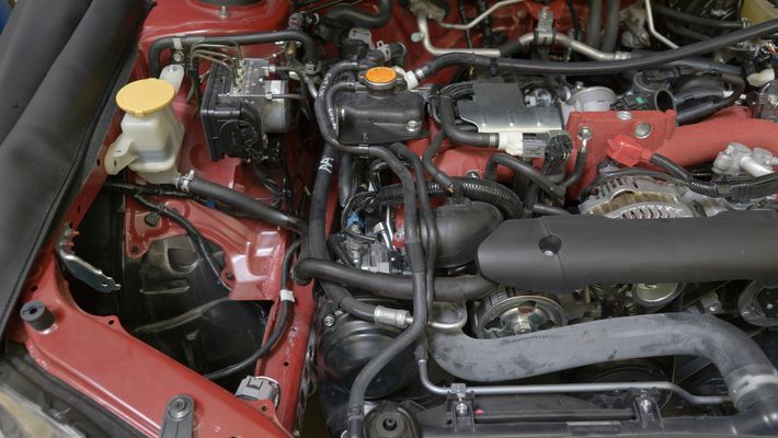
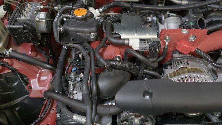
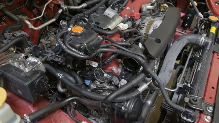
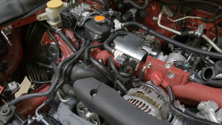
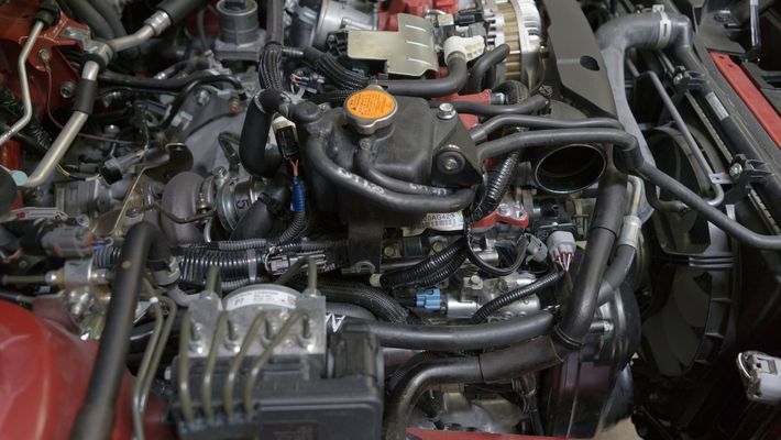
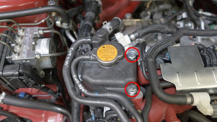
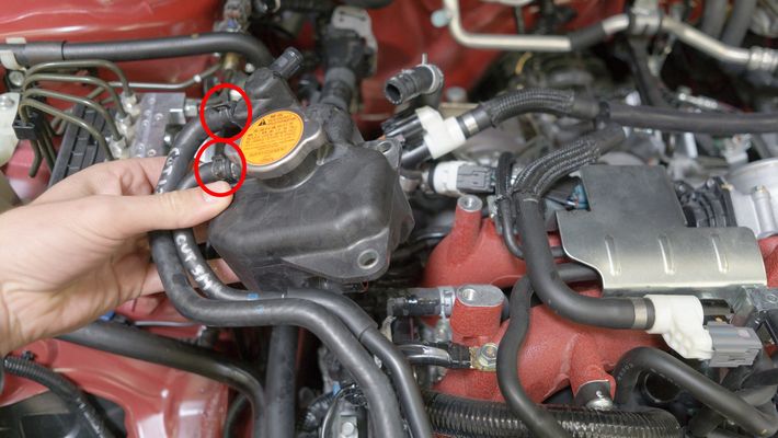
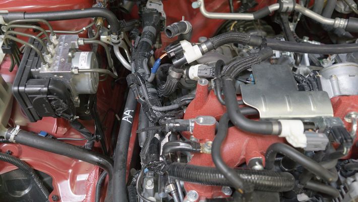
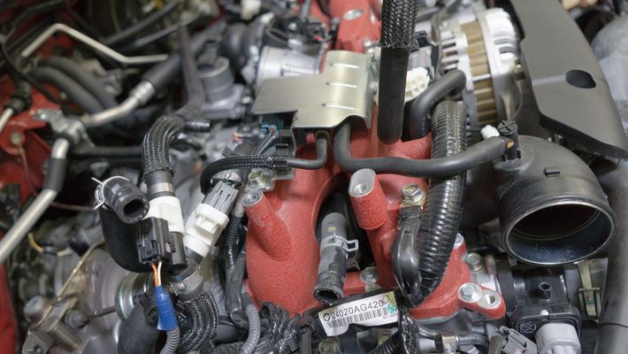
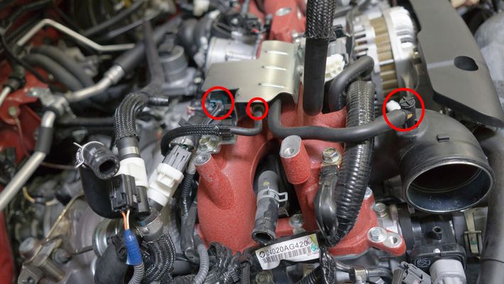
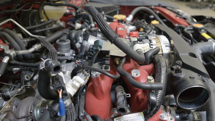
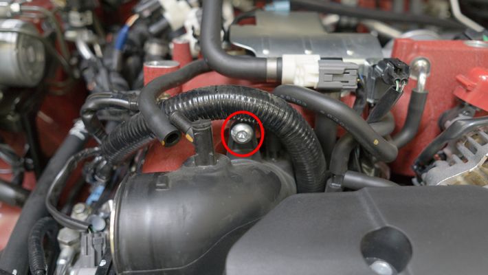
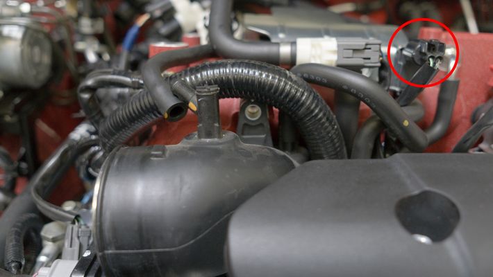
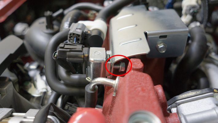
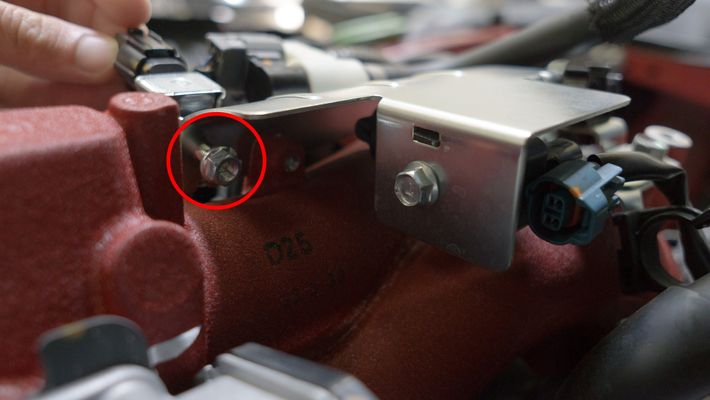
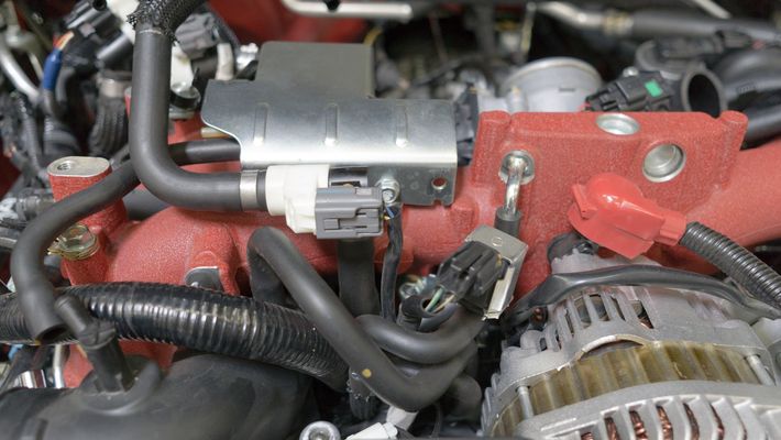
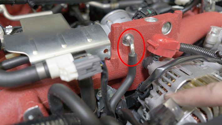
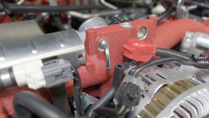
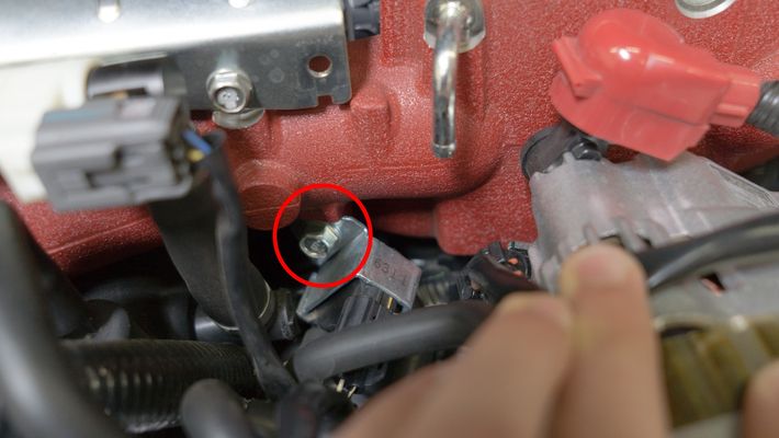
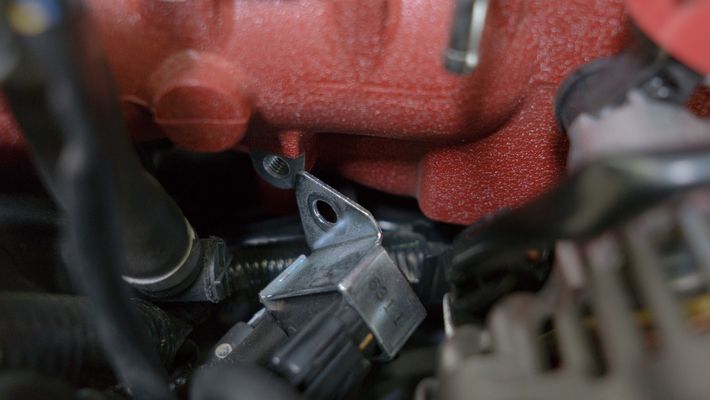
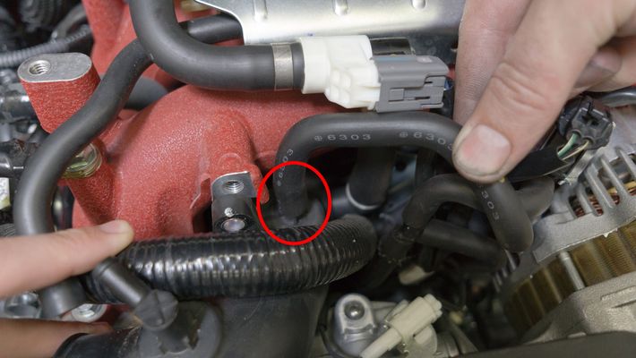
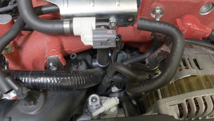
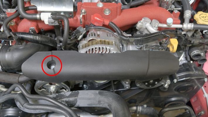
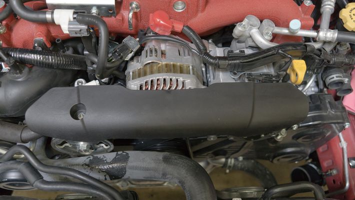
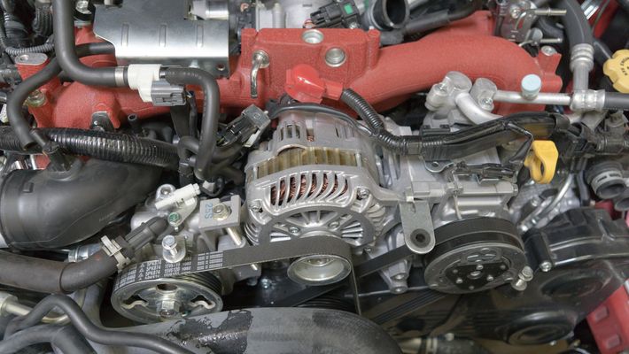
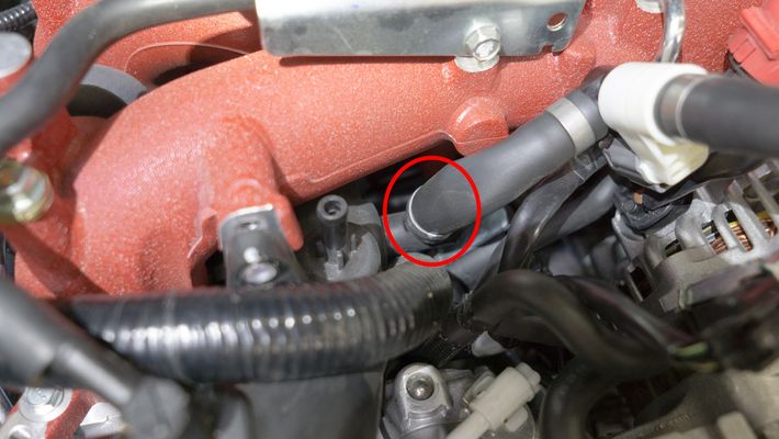
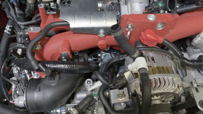
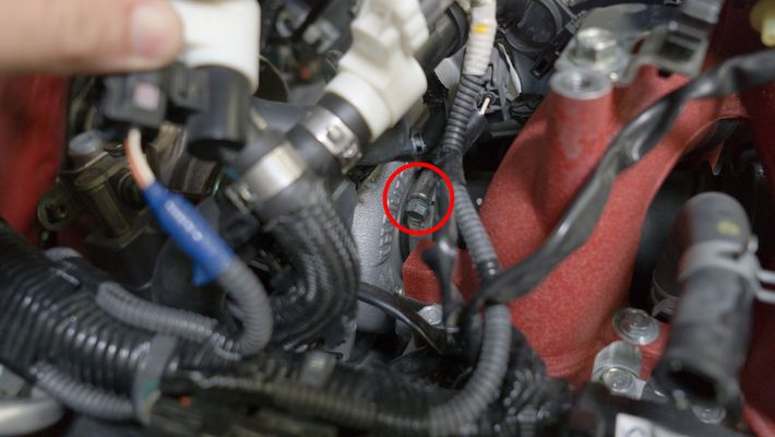
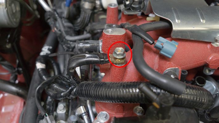
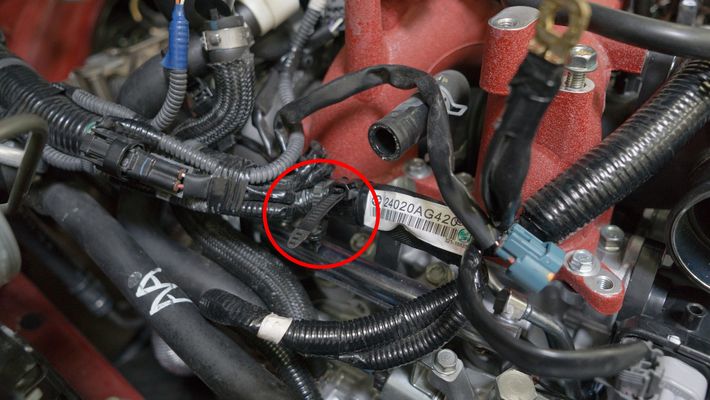
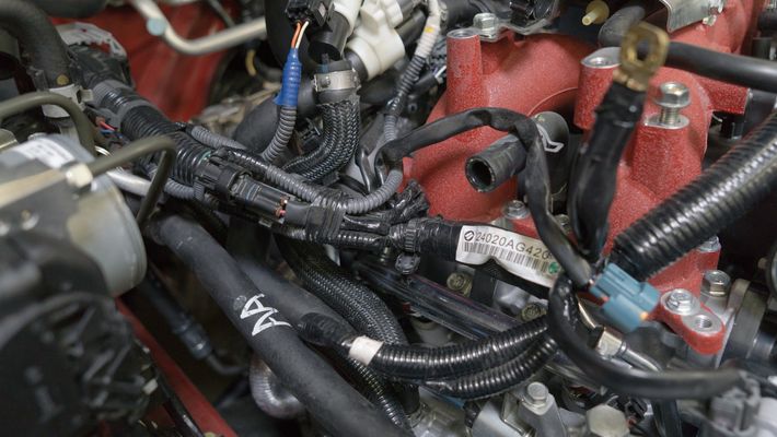
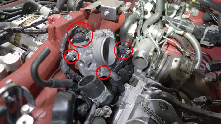
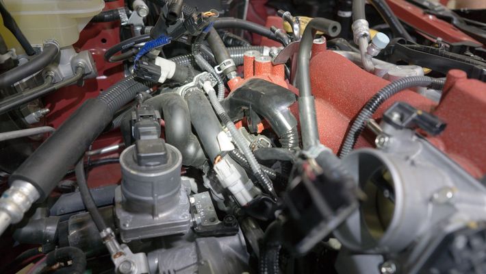
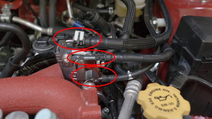
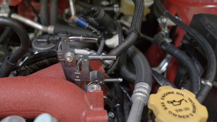
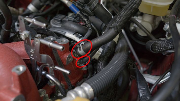
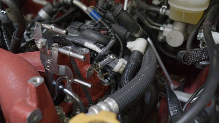
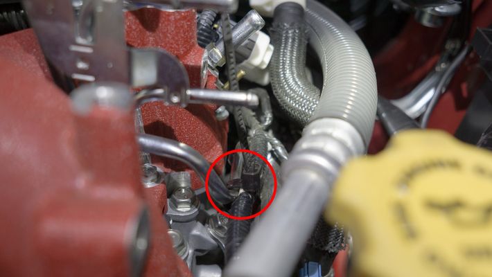
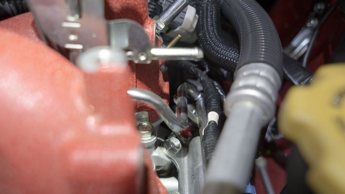
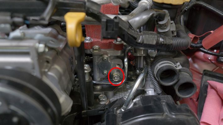
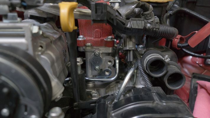
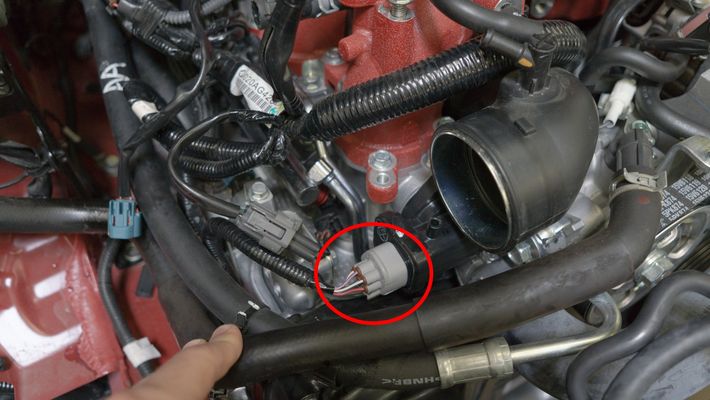
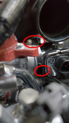
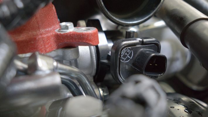
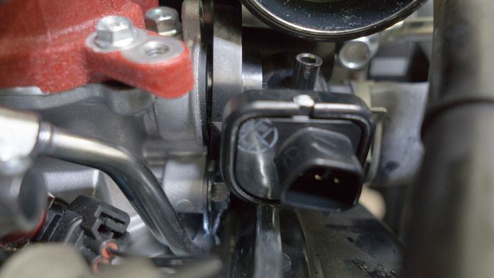
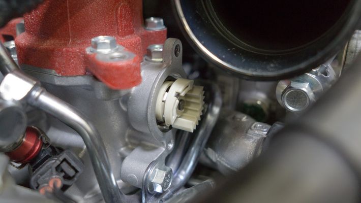
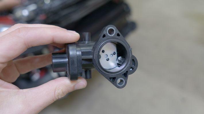
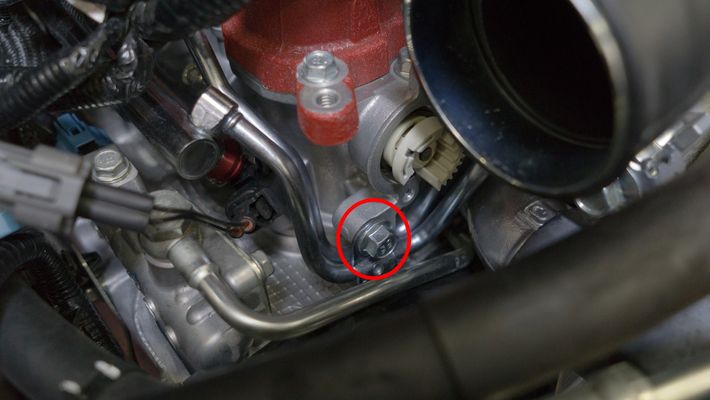
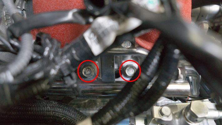
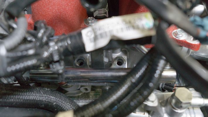
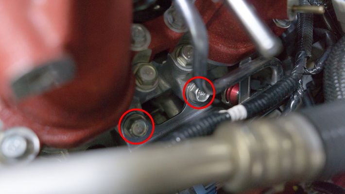
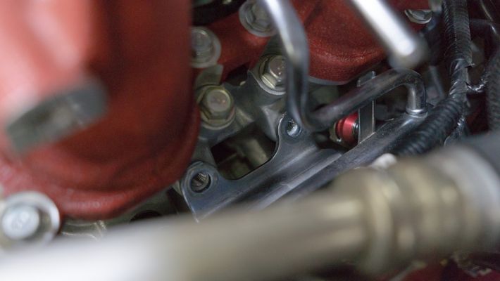
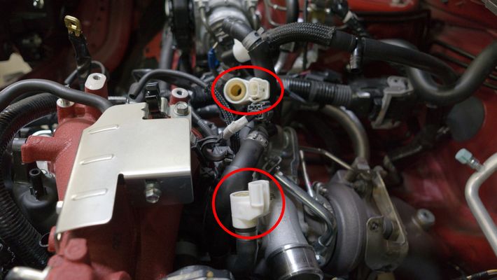
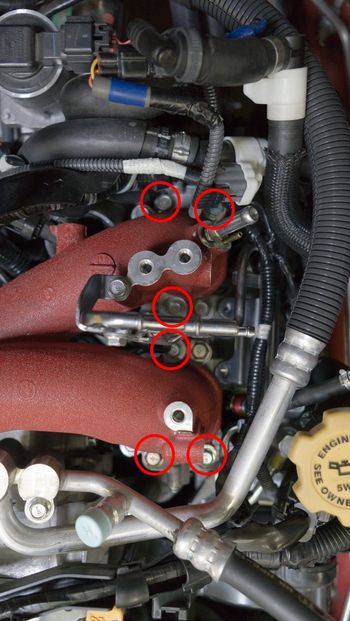
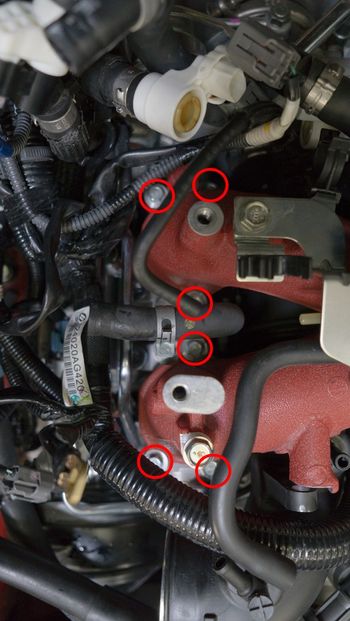
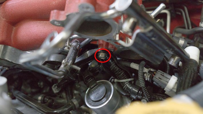
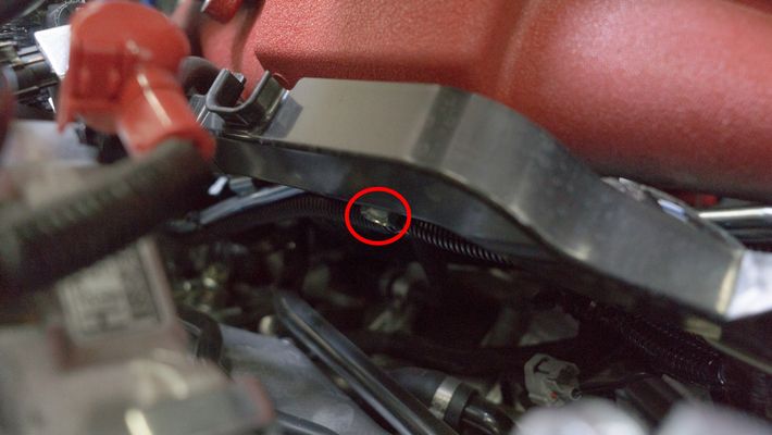
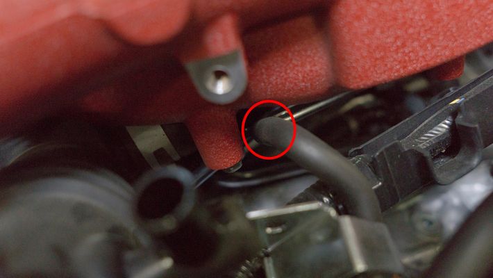
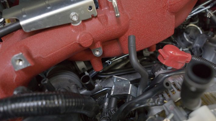
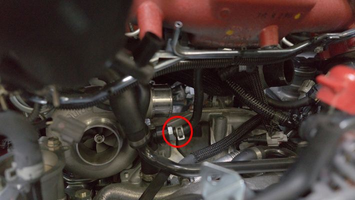
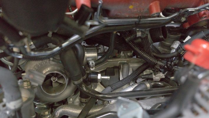
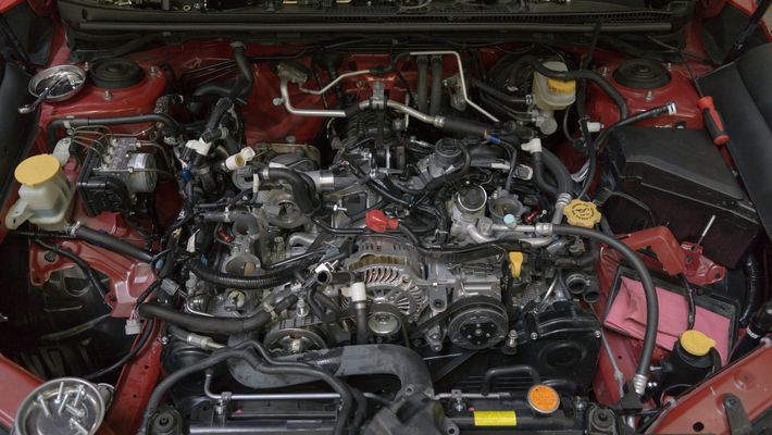
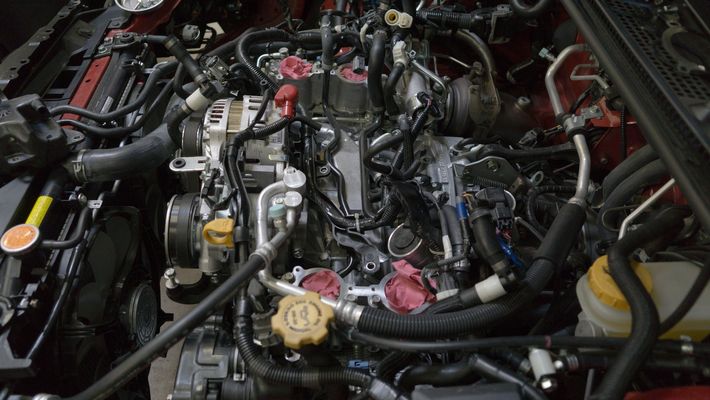
We perform this removal on a 2017 STI.  While this is incredibly similar to the other models of EJ engines used over the years there may be small differences from vehicle to vehicle.


  1. You'll want to begin by taking plenty of pictures of your vacuum hose routing. This will be critical for when you're putting everything back together.


  2. With the car cool to the touch, we recommend draining the overflow coolant overflow reservoir. There is a small Phillips head bolt on the passenger side of the bottom of the radiator.

  3. Remove the coolant overflow reservoir by removing the (2) 12mm bolts.


  4. Remove the top and bottom coolant lines going to the overflow reservoir using a pair of pliers.

    Using a proper hose clamp can help reduce any spillage of fluids and reduce the amount of time required to bleed the cooling system later on.


  5. Disconnect the electronic boost control solenoid (EBCS). There will be (3) connection points, 5/16" line to the turbo inlet hose, a 1/4" line to the wastegate, and an electrical harness (blue).


  6. Remove the 6mm hex head bolt on the front of the intake manifold holding the turbo inlet on.


  7. Remove the 10mm bolt on the rear of the EVAP sensor.


  8. Remove the intake manifold vacuum line.


  9. Remove the 12mm bolt holding the purge valve on the intake manifold.


  10. Disconnect the 3/8" vacuum line from the top of the turbo inlet hose.


  11. Remove 10mm bolt securing the alternator cover. There is a push-type connector on the underneath the right-hand side.


  12. Remove the PCV hose from the turbo inlet hose. You may need to cut off a metal clamp that is installed from the factory.


  13. Loosen the 10mm clamp securing the turbo silicone to the turbo.


  14. Disconnect the 12mm bolt securing the ground.


  15. Remove the zip tie holding the wiring harnesses together.


  16. Disconnect the MAP sensor, throttle position sensor wiring harness, and upper and lower coolant hoses.


  17. Disconnect the 12mm retainer bolt for the electrical harness on the back of the intake manifold.


  18. Disconnect the fuel lines from the intake manifold.

    We typically recommend marking the lines with some sort of tape or colored zip tie to ensure you put them back in the same place.


  19. Disconnect the brake booster hose and the fuel pressure regulator reference.


  20. Remove the zip tie holding the wiring harness to the fuel rail.


  21. Remove the 12mm bolt from the fuel rail bracket to the TGV.


  22. Remove the TGV electrical harness.


  23. Remove the (2) 10mm bolts holding the TGV to the manifold. 


  24. Gently and carefully remove the TGV from the manifold.

    BE CAREFUL TO VERIFY THE POSITION OF THE GEARS AND DO NOT DAMAGE THE O-RING. It helps to take a picture in order to verify its orientation. or mark it using a marker.  This needs to be back in the original orientation when you go to put it back together.


  25. Remove the 12mm bolt holding the fuel line to the manifold.


  26. Remove the (2) 12mm bolts holding the fuel rail on the passenger side.


  27. Remove the (2) 12mm bolts holding the fuel rail on the driver's side.


  28. Disconnect the (2) PCV hoses


  29. Remove the (6) 10mm bolts securing the intake manifold on the passenger's side.


  30. Remove the (6) 10mm bolts securing the intake manifold on the driver's side

    After the bolts are loose, you can use a magnet to remove them easier.


  31. Gently lift the fuel rail, pushing down on the injectors to keep them seated. You cannot completely remove the intake manifold yet. This step is for gaining clearance to the underside, so do not force it.

    A small amount of fuel will spill, so it's a good idea to have a rag handy to catch it.

  32. After you've lifted the intake manifold slightly, there will be (2) 12mm bolts underneath that you need to remove. (1) is on the underside-middle, the other is on the underside-driver.


  33. Disconnect the vacuum line from the passenger side of the intake manifold.


  34. There is one remaining vacuum line that you will need to remove near the backside of the intake manifold.


  35. Gently remove the intake manifold. Be cautious of the TGV gears and the (2) intake manifold gaskets.NOTE: You may need to move the wiring harnesses around to allow clearance for the intake manifold. 

    Once removed, we recommend covering the exposed ports to prevent foreign material contamination.


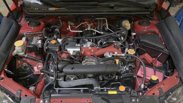
Copyright 2023 © COBB Tuning Products LLC. All Rights Reserved. | www.cobbtuning.com