Subaru Speed Density Guide: 2.0, 2.5L, DIT
- Mike McGinnis
- Former user (Deleted)
- Brandyn Mowat


Subaru Speed Density Guide
Version 2
10/09/2019
Introduction
Note: This guide covers COBB Speed Density for EJ 2.0L, EJ 2.5L and DIT Subarus.
Overview
The COBB Speed Density feature is a powerful yet easy-to-use solution that integrates Speed Density tuning into the Subaru engine control unit (ECU) and can be used to entirely replace or work in conjunction with the existing factory mass airflow (MAF) sensor. It is highly customizable and features such as real-time tuning aid in a speedy and efficient tuning process.
Uses
COBB Speed Density (SD) has a number of potential uses that can improve the tuning capability for particular set-ups:
- SD can eliminate the noisy airflow calculation sometimes seen when using a MAF sensor-based configuration with heavily modified cars.
- SD allows for the MAF sensor to be removed, eliminating a potential restriction in the intake tract and allowing for more freedom in intake piping design.
- In a special hybrid mode, SD can be used on the high end to overcome a maxed out MAF sensor, while still retaining MAF sensor operation on the low end. Or SD can be used on the low end to improve idle/cruise characteristics when a big MAF is used, while still retaining MAF sensor operation on the high end.
Glossary of Acronyms
- CCF = Cobb Custom Features (generally referring to the CCF ECU type which contains custom features not otherwise available on the factory ECU)
- DIT = Subaru's "Direct Injection Turbo" motor (14-18 FXT, 15+ WRX)
- DIT Gen2 = A second generation CCF ECU for DIT vehicle types that adds additional features (including SD) over the Gen1 DIT CCF type
- ECT = Engine Coolant Temperature
- ECU = Engine Control Unit
- EJ 2.0L = Subaru's port-injected EJ 2.0L motor (02-05 WRX)
- EJ 2.5L = Subaru's port-injected EJ 2.5L motor (04-13 FXT, 05-12 LGT, 05-09 OBXT, 04+ STi, 06-14 WRX)
- IAT = Intake Air Temperature
- IC = Intercooler
- MAF = Mass Airflow
- MAP = Manifold Absolute Pressure
- RPM = Revolutions Per Minute (referring to engine speed)
- SD = Speed Density
- VE = Volumetric Efficiency
- WBO2 Sensor = Wideband Oxygen Sensor
- CCF = Cobb Custom Features (generally referring to the CCF ECU type which contains custom features not otherwise available on the factory ECU)
Features
The following is a list of the key features of COBB Speed Density (SD):
- SD works by calculating a new SD-based airflow to replace the factory MAF sensor-based airflow when SD is active. This keeps much of the existing factory logic in place, allowing for the safe and reliable operation of the factory ECU while reducing the learning curve associated with tuning SD.
- Tuning SD is achieved through manipulating a real-time tunable volumetric efficiency (VE) table. Because the VE table units represent actual VE, properly calibrated SD tunes can be used to compare VE across different cars with different mods, even if the SD airflow is drastically different.
- A real-time tunable intake air temperature (IAT) compensation table allows the tuner to tweak the SD charge temperature correction. This table can be tweaked according to manifold pressure, allowing for changes that may be needed based on IAT sensor placement. SD airflow compensations for engine coolant temp (ECT) and barometric pressure are also available.
- Tuners can select from three different real-time tunable modes of operation. MAF mode mimics the factory logic in which airflow is determined by the MAF sensor and the MAF Calibration table. This mode allows you to get a starting VE table up and running before actually running SD or allows you to tune MAF sensor calibration as you would with the factory ECU. SD mode is a full-time SD operation where the ECU uses the SD-based airflow calculation. Hybrid mode allows for switching between MAF and SD mode (and vice versa) based on thresholds of the throttle, RPM, MAP and MAF voltage. During the transition, the MAF sensor and SD-based airflow calculations will be blended over a short period of time to allow for a smooth transition between modes. The speed of this transition and how the switching takes place can also be configured.
- The SD and MAF sensor-based calculations are made regardless of mode. This means the MAF sensor-based airflow can be compared to SD airflow regardless of which airflow value is currently being used.
- For cars with a properly calibrated and installed MAF sensor, an available estimated VE monitor can be used to more quickly get the initial tune for the VE table up and running. This can even be done in MAF mode, where the VE table (and other SD elements) can still be tuned before actually running SD.
- Because the response characteristics of the MAF sensor (used in MAF mode) and the MAP sensor (used in SD mode) are different, a tunable airflow or load smoothing factor is available. This determines how airflow or load is filtered by the ECU and allows for better idle and tip-in/tip-out behavior in SD mode.
- DIT vehicles have 3 VE tables plus a stratified mode VE adder to allow further optimization in relation to TGV and AVCS positions.
Hardware Requirements
The following minimum hardware requirements must be met in order to use the SD feature:
- MAP Sensor - The manifold absolute pressure (MAP) sensor installed in the car must be accurate, reliable, and capable of reading boost greater than the car can ever achieve. A typical car that would necessitate an SD tune would likely max out the factory MAP sensor and require an aftermarket MAP sensor to be installed. Any aftermarket MAP sensor must be properly scaled in the map (via the MAP Sensor Calibration (Offset) and MAP Sensor Calibration (Multiplier) tables) and its accuracy should be verified by an external boost gauge before tuning SD. Note: A MAP sensor related check engine light can cause a failsafe load calculation to come into play, potentially causing issues when SD mode is active (please see "Tuning SD – Initial Map Configuration" section for more details).
- IAT Sensor (EJ 2.0L/2.5L) - The vehicle must have a working, accurate and properly calibrated intake air temperature (IAT) sensor. The IAT sensor is crucial to the SD airflow calculation. The SD airflow calculation relies on a theoretical input of the cylinder charge temperature. The closer the IAT reading is to the actual cylinder charge temperature, the more accurate (and consistent) the SD airflow calculation will be and the easier SD will be to tune. The factory IAT sensor is in the MAF sensor assembly in a draw-through configuration (i.e. pre-turbo). While it is possible to tune SD with an IAT sensor in this location, it is more difficult and will require more tweaking of the SD IAT compensation table (because this placement does not take into consideration turbo and intercooler efficiency). We recommend the IAT sensor be placed post-intercooler, if possible. This could be using the factory MAF/IAT sensor assembly moved to a blow-through configuration (i.e. post-front mount intercooler) or an aftermarket IAT sensor placed in the intake piping in the same location (see appendix for details on how to install an aftermarket IAT sensor). Keep in mind an aftermarket IAT sensor will require a different calibration than the factory IAT sensor.
- IAT Sensor (DIT) - The DIT cars have two intake temp sensors - one in the MAF assembly (i.e. pre-turbo) and one in the intake manifold (i.e. post-turbo/IC). DIT SD only uses the intake manifold input for its SD airflow calculation as this is closer to actual cylinder charge temperature.
- Other Sensors - Any sensor or component necessary for the operation of the factory ECU must be working, installed, and properly calibrated. The only exception is the MAF sensor assembly if the tune is set to run only in full-time SD mode (see "MAF Sensor Removal" below).
- MAF Sensor - The MAF sensor assembly must be installed and properly calibrated if the MAF mode, hybrid mode, or estimated VE monitor is to be used. For EJ 2.0L/2.5L, it must also be installed if the factory IAT sensor (which is part of the MAF sensor assembly) is to be used for SD (rather than an aftermarket IAT sensor).
- MAF Sensor Removal - If the MAF sensor is removed, disconnected, or otherwise non-functional, you will only be able to run the car in full-time SD mode and the car will not start or run when MAF mode is active. This would also trigger some of the MAF sensor related diagnostic trouble codes (DTCs) such as P0101, P0102, and P0103. While the ECU's primitive failsafe load calculation has been disabled in the COBB CCF ECU (when SD mode is active), other fail-safe logic can come into play when MAF DTCs are active. Also, removal of the factory MAF sensor assembly also removes the factory IAT pre-turbo sensor requiring you to install an aftermarket IAT sensor for the EJ 2.0L/2.5L cars.
- Wideband Oxygen Sensor - A properly functioning and installed wideband oxygen sensor (wbo2) is necessary to tune SD. The EJ 2.0L/2.5L front o2 sensor is not scaled for full range operation from the factory, and cannot read accurately at high engine load due to high exhaust pressure in that location. The factory DIT front o2 sensor (in the stock location), on the other hand, can be used for SD tuning. In addition to an accurate wideband reading, it is highly recommend that the driver have a means of easily monitoring this reading such as an interior gauge (EJ 2.0L or EJ 2.5L without CCF custom input) or via the Accessport (AF Sens 1 Ratio monitor for DIT or Sensor Input Monitor Only... for EJ 2.5L CCF custom input set-up).
- Mechanical Issues - Any mechanical problem with the car needs to be addressed before attempting to tune SD.
- Manual Transmission Only (EJ 2.0L) - COBB CCF for the 02-05 WRX supports manual transmission cars only. Although the Accessport will still allow you to install COBB CCF on a 2.0L WRX with an automatic transmission, it has not been tested on this combination and the vehicle may not run or may have severe driveability and safety issues.
Warnings
OFF-ROAD USE ONLY
Some or all of the features and modifications discussed in this guide may not be legal to use outside of off-road racing applications. Always consult local, state and federal laws to determine what is legal for your particular situation.
READ ALL DOCUMENTATION BEFORE TUNING
COBB SD is not like other SD systems you may be familiar with, including even COBB implementations for other platforms. As such, it is critical you read through this guide and understand how COBB SD for Subarus works before attempting to tune. If you have any questions, we are always willing to help.
SD IS NOT FOR INEXPERIENCED SUBARU TUNERS
There are many unique qualities to Subaru ECU logic which can make it challenging for someone new to the platform. If you are new to Subaru tuning, it is recommended you first become proficient at tuning MAF sensor-only set-ups before tackling SD tunes. MAF sensor-only tuning can be much more forgiving to mistakes than SD tuning.
VERIFY FACTORY AIRFLOW AND LOAD LIMITS AND RAISE AS NEEDED
It is important to understand the factory airflow and load limits are still applied even when the SD-based airflow is being used. Please see the "Tuning SD – Initial Map Configuration" section for more details. Failure to raise these limits appropriately could result in engine damage as the calculated airflow and/or load becomes static past a certain point.
MANIFOLD PRESSURE SENSOR CHECK ENGINE LIGHT ERRATIC LOAD CALCULATION
Any diagnostic trouble code (DTC) related to the manifold pressure sensor will cause the Subaru ECU to estimate manifold absolute pressure (MAP) based on the current calculated load (as a failsafe). This can result in an erratic load calculation in SD mode because actual MAP (a key input for SD) would no longer be determined correctly. If this occurs when the vehicle is accelerating, a lean condition and incorrect timing can result. It will also likely cause the engine to eventually stall. It is critical no MAP sensor related DTCs (such as P0068, P0107, or P0108) are active when SD mode is active. The installation of an aftermarket MAP sensor (required for SD if the factory MAP sensor is not sufficient) will make it more likely for these DTCs to be triggered, even though there may be nothing wrong with the sensor itself. Please see the "Tuning SD – Initial Map Configuration" section for more details.
ENGINE HARDWARE CHANGES MAY REQUIRE A RE-TUNE FOR SD
It is important to understand after the SD tune is complete for a given car, any further changes to engine hardware which impact airflow efficiency in or out of the engine can potentially require tweaking or re-tuning of the VE table to avoid fueling/timing issues (due to incorrectly calculated SD load). Additionally, mechanical issues, such as intake/exhaust leaks, and issues related to the aging of the motor, such as combustion deposits and loss of compression, can also impact actual VE. For EJ 2.0L/2.5L, it is highly recommended that a permanent wideband o2 sensor and gauge (or CCF custom input for applicable EJ 2.5L) is installed in the vehicle and the driver understands how to properly monitor it under different conditions. For DIT, the driver should be instructed on how to monitor the factory front o2 reading via the AF Sens 1 Ratio monitor under different conditions.
POTENTIAL RISKS FOR SD WITH A HEAT SOAKED INTAKE TEMP SENSOR
Any SD calculation, including COBB SD, requires input for cylinder charge temperature, which is critical to the determination of accurate airflow via SD. The estimation of cylinder change temperature is accomplished for COBB SD via the intake temperature (IAT) sensor input. Generally, when the IAT sensor is in the recommended location (post-intercooler), the vehicle is moving and the driver is on the throttle, the IAT input can be a fairly reliable representation of actual cylinder charge temp. However, when the vehicle is sitting still (or at low speeds) and the driver is off the throttle (or low throttle), or the vehicle has been sitting with the engine off and a hot engine bay for a period of time, there is the potential for the IAT sensor to become heat soaked. That is, the sensor now reads higher than the actual intake air temp. When SD is active, this would cause the calculated SD airflow (as well as load) to be lower than it should be, causing the car to run lean (and with generally more timing advance). This effect may subside after the vehicle gets moving and throttle (as well as MAP) increases, but it will generally not be an instantaneous improvement. As such, it is critical the owner/driver of the car understands the specific scenarios in which a heat soaked IAT sensor can potentially occur and to avoid putting the car under high load when these scenarios are present (and for a period shortly after). This is another reason why wideband o2 monitoring is critical in SD mode and the driver understands how to determine when fueling is incorrect.
SD Installation Steps
Before tuning with SD, you'll first need to make sure you are on the latest Accesstuner software and the latest Accessport firmware. Always make sure to periodically check for future updates as well.
- Use the Accesstuner auto-updater to grab the latest version of the software via the internet ("Help" → "Updates" → "Check for Updates").
- Update your Accessport firmware to the latest version via the Accessport Manager software.
- Now that your software and firmware are updated, you will need to reflash the latest version of a CCF/SD-capable map to the car you will be tuning.
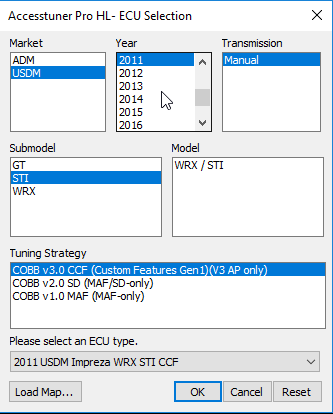
- Run the Accesstuner software and select the latest COBB Custom Features (CCF) ECU type (CCF V3.0+ for EJ 2.0L/2.5L or CCF V4.0+ for DIT) for the vehicle you wish to tune. If a CCF ECU type is not available for the vehicle, choose the COBB v2.0 SD ECU type if supported.
- You may now import values from one of your existing tunes or start from the default stock mapping in Accesstuner. Please note you may not be able to import all tables due to changes in code to facilitate higher load/boost limits. Make any initial changes to this map you wish to start from for SD (see "Tuning SD – Initial Map Configuration" later in this document).
- Save your map. This map will now have the SD feature.
- Transfer the map to the Accessport with the Accessport Manager software.
- Reflash the new SD map to the car via the Accessport.
- The car is now ready to be tuned via SD.
SD Basics
What is Speed Density?
The Subaru ECU, as well as any engine management solution, needs to determine the mass of air entering the engine in order to determine the correct amount of fuel to inject for a given desired fueling target. With the Subaru ECU, it is represented in terms of mass airflow (grams per second), which, along with engine speed (RPM), is used to determine load (grams per crankshaft revolution). For the Subaru ECU, the load is not only used to determine the proper injector pulse width, but also the desired fueling/timing targets. The modern factory Subaru determines mass airflow via the mass airflow (MAF) sensor. The MAF sensor-based system attempts to directly measure the actual mass airflow (given the relationship between MAF voltage and airflow for a specific intake and sensor).
Speed Density, on the other hand, attempts to estimate mass airflow via other inputs. The basis for this calculation is given by the ideal gas law. The ideal gas law is a relationship in physics between various inputs which allows for an estimation of the mass of an ideal gas. In our case, the ideal gas is the air entering the combustion chamber of the motor. The variables involved in the calculation (for COBB SD) include manifold absolute pressure (from the MAP sensor), cylinder charge temperature (i.e. approximated by our IAT sensor input), volumetric efficiency (from our VE calibration table), engine speed (RPM), and engine displacement (tunable parameter). From this, an estimation of mass airflow can be made (see the "SD Math" section for a detailed explanation of the math involved).
What is Volumetric Efficiency?
Simply put, it is the amount of air inducted into the engine relative to the engine's displacement. An engine is essentially an air pump and volumetric efficiency (VE) defines how efficient that process is. Volumetric efficiency of 100% would indicate the amount of air inducted is the same as the engine displacement (at standard conditions) for a given engine cycle. If all engines always operated at 100% VE, there would be no need to account for VE in determining the SD airflow. But, this is far from the case.
Numerous factors impact how VE varies with conditions for a given engine. As far as engine hardware, this can include, but not limited to, the entire intake tract (from the air filter to the turbo to the intercooler to throttle body), all exhaust components, intake manifold design, cylinder head design, intake/exhaust valve design, compression ratio, camshaft timing and lift (including variable valve timing via tuning), and so on.
Mechanical/aging issues, depending on their severity, can also potentially impact VE. Examples would include combustion deposits, intake/exhaust leaks, and loss of engine compression.
Among engine operating inputs, VE is most likely to change according to manifold absolute pressure (MAP) and engine speed (RPM). This is why the VE table uses MAP and RPM axes (as is typical with most SD solutions).
Volumetric Efficiency Table
The VE table is the primary means by which an SD tune is accomplished for a given car. Once tuned, changes to engine hardware and/or mechanical/aging issues that arise (as described in the section above) may require re-tuning of the VE table. What areas of the table need to be re-tuned or tweaked is going to depend on the change itself and how it impacts actual VE across a range of MAP and RPM.
Tuning the VE table is simply determining the actual VE so the SD airflow is as close to the actual airflow as possible. This can be accomplished by comparing the ECU's fueling target with actual fueling (via wideband o2 sensor). All things being equal, increasing VE in the VE table will result in an increase in SD airflow (for the MAP/RPM area impacted). This will result in an increase in load and fueling will become richer. On the other hand, decreasing VE in the VE table will result in a decrease in SD airflow. This would have the opposite effect with load decreasing and fueling becoming leaner. Keep in mind that the load is also used as an input to ignition timing, cam timing (AVCS), and the primary fuel tables (among other tables), the change in the load will also impact the desired targets for these tables.
The peak VE for a given column of the VE table will generally occur at the RPM of the motor's peak torque and VE will progressively drop on either side of that RPM point. Also, VE generally tends to increase as MAP increases. Keep in mind these are not hard and fast rules. You may find the VE tune necessary for a given car does not follow these guidelines completely.
SD Load Replaces SD Airflow for EJ 2.0L (02-05 WRX)
The COBB SD implementation for the EJ 2.0L modifies engine load directly when SD is active instead of mass airflow (which is directly modified in the EJ 2.5L and DIT implementations). Mass airflow for the EJ 2.0L, when SD is active, is back-calculated from RPM and the new SD-derived load. The net effect, however, is identical in operation as the EJ 2.5L and DIT SD feature. Just keep in mind that when this document mentions "airflow", this will actually be "load" for the EJ 2.0L (including how the monitors and tables are named).
SD Modes
COBB SD gives you the option of running several different modes that determine how airflow will be calculated. The modes are determined by the following SD Mode table:
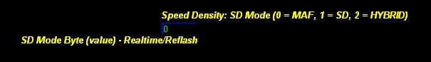
MAF mode – A value of 0 in this table will enable full-time MAF mode. This results in airflow being determined exactly as the factory ECU logic dictates. That is, airflow is determined based on MAF sensor input and the MAF Calibration table. This requires the MAF sensor is still installed, functional and properly calibrated. In this mode, the SD airflow will still be calculated even though it is never used. This will allow you to compare the SD airflow to the MAF sensor-based airflow via the SD Airflow POST COMP monitor and the Mass Airflow TABLE (EJ) or Mass Airflow Corrected OEM (DIT) monitor. In addition, you can also tune the SD tables in this mode. The SD VE Estimated MAF monitor (which is available in any mode) will estimate VE based on the MAF sensor-based airflow (and other inputs) which you can use as a reference to get an initial tune of the VE table started. In MAF mode, this will allow you to make changes to the VE table while still running the MAF sensor-based tune.
SD mode – A value of 1 in this table will enable full-time SD mode. That is, the airflow normally determined by the MAF Calibration table in the factory ECU will always be replaced by the SD airflow calculation determined by your SD tune. Even though the MAF sensor-based airflow will not be used by the ECU in this mode, you can still monitor/log this value via the Mass Airflow TABLE (EJ) or Mass Airflow Corrected OEM (DIT) monitor. If the MAF sensor is still installed, functional and properly calibrated, you can use this value as a comparison to the SD airflow determined by your SD tune.
Hybrid mode – A value of 2 in this table will enable hybrid mode. This allows you to switch to either MAF or SD mode based on a series of tunable thresholds for throttle, RPM, MAP and MAF voltage. That is, you can decide when the ECU will use the MAF sensor-based airflow and when it will use the SD calculated airflow. When transitioning between MAF and SD mode (or vice versa), the current airflow will be a blend of the two mode calculations to allow for a smooth transition. The speed of this transition can be tuned.
Tuning SD – Mechanical Configuration
Before jumping in and starting tuning, make sure the car meets the minimum hardware requirements outlined in the "Hardware Requirements" section found earlier in this document. Failure to do so can result in an inconsistent tune as well as potential engine damage.
Tuning SD – Getting Started
- Installing SD – Make sure a CCF map (or SD map if CCF is unavailable) has been reflashed to the car's ECU and you have the latest Accesstuner software and Accessport firmware updates as outlined in the "SD Installation" section earlier in this document.
- Opening Map – Run the Accesstuner software and select the proper vehicle and the CCF (or SD) ECU type corresponding to your map. Open the map you reflashed to the vehicle.
Tuning SD – Initial Map Configuration
Airflow and Load Limits (EJ 2.5L only)
Because most of the factory logic is retained for COBB SD, factory limits that cap airflow and load are still applied. It is critical these limits are double checked for your tune. Otherwise, it could cause a dangerous lean condition where the calculated airflow/load is capped even though actual airflow/load is still increasing. This is true regardless of whether SD airflow or MAF sensor-based airflow is being used. The following outlines how to check and raise the airflow/load limits:
- Raising Factory Airflow Cap – This is as simple as raising the value in the MAF Limit (Max) table, located in the "Miscellaneous Limiters" table group. This should be raised to a value the car will never hit under any circumstances. For SD ECUs, the default for this table has been raised to 2000 g/s (from the factory 300 g/s), although this can be overridden by the map you are opening, so be sure to double-check this limit.
- Raising Factory Load Cap – If the ECU you are tuning only has a single load limit table (Load Limit (Max) Primary under the "Miscellaneous Limiters" group), then raising the load cap is as simple as raising the value in this table. If, however, the ECU has the second load limit table (Load Limit (Max) Secondary), the process is more involved. First, raise the Load Limit (Max) Primary to your new limit. Second, raise all the Load Limit (Max) Secondary load values to their max of 4.0 g/rev. Third, raise all the Load Limit (Max) Secondary Compensation (Barometric) values to 100%. Do the same for Load Limit (Max) Secondary Compensation (Intake Temp) table. The 100% compensation across both tables will result in doubling the secondary load limit twice. For example, if the secondary load limit was 4.0 g/rev, the new load limit (with 100% in all cells of secondary compensation tables), would be 4 * 2 * 2 = 16 g/rev.
Airflow and Load Limits (EJ 2.0L only)
The COBB CCF ECU significantly raises the airflow and load limits inherent to the 02-05 USDM WRX ECU. There is no need to deal with hacks that, for example, halve the airflow/load references and double the fuel injector scale. Instead, you simply tune with the real-world actual airflow, load and fuel injector scale values. The COBB SD ECU allows you to tune up to 10.0 g/rev of load for MAF and SD operations. And up to 655 g/s of airflow for MAF operations. Because SD load is directly calculated so there is no need to worry about an airflow limit for SD operation.
Manifold Pressure Sensor Setup and Diagnostic Trouble Codes
When using an aftermarket MAP sensor, be sure to set the multiplier, offset and DTC thresholds accordingly. Settings for some common sensors are listed in the "Calibrations for Aftermarket MAP Sensors" section.
If a check engine light is set related to the manifold absolute pressure (MAP) sensor, the ECU will switch to an alternate failsafe calculation for manifold pressure. For EJ, this alternate calculation is based on load. Because MAP is a key input to the load calculation in SD mode, this results in a feedback loop in which actual MAP no longer plays a role in determining SD load. This erratic load calculation could cause a dangerous lean condition (with incorrect timing), if the actual MAP is increasing at the time (for example, if the vehicle was accelerating). It will also likely cause the car to eventually stall.
One or more of the MAP sensor diagnostic trouble codes (DTCs) can even be set when there is no actual failure of the MAP sensor. This can occur in the following circumstances:
- A high level of boost (i.e. MAP voltage) is seen by the factory or aftermarket MAP sensor that exceeds the factory DTC limits.
- A lower level of MAP voltage due to the aftermarket MAP sensor's expanded relative range.
- Higher or lower MAP voltage than the ECU expects based on thresholds for RPM, throttle, and load.
The following are the MAP sensor related DTCs in question:
P0068 - MAP/MAF - Throttle Position Correlation
- P0107 - MAP Sensor Circuit Low Input
- P0108 - MAP Sensor Circuit High Input
It is critical DTC limits be adjusted in order to avoid unwanted behavior. Please check with your sensor supplier if you are unsure of the appropriate limits. If the sensor you are using can experience the full 0-5V range during normal operation, you will need to disable error checking by disabling these codes.
For the P0107 and P0108 codes, the DTC voltage limits can be configured in the Accesstuner software via the MAP Sensor Voltage DTC Limits... table (found in the "Boost Control Tables" → "Boost Limiters" group). Additionally, the MAP Sensor Voltage DTC Delays... table determines how long the voltage limit must be exceeded before the DTC is set. Both of these tables can be used in place of disabling these two DTCs if a proper range can be determined. For the SD ECU, the defaults of these values have been expanded, although this can be overridden by the map that is opened. Keep in mind the P0068 DTC limit is not configurable in the software. This DTC is set when MAP voltage is not above or below certain thresholds given specific conditions related to RPM, throttle, and load.
Load and MAF Compensation (EJ 2.0L/2.5L only)
In addition to the airflow/load limits, the factory airflow/load compensations are still applied to the SD-based and MAF sensor-based airflow/load calculations. It is important to look at and understand these compensations as they will ultimately determine the final airflow and load used:
- MAF Compensation - The airflow compensation table is called MAF Compensation (Intake Temp) and can be found under the "Sensor Calibrations" group. This determines the compensation to airflow based on IAT and current airflow. Generally speaking, this compensation is not needed for SD tunes (some ECUs have this zeroed-out from the factory, to begin with). If you are running in hybrid mode, you can retain the compensations when MAF mode is active by separately manipulating the compensations above and below an airflow breakpoint in the table which would represent the approximate switchover point of your hybrid tune for MAF to SD (and vice versa).
- Load Compensation - The load compensation table is called Load Compensation (Manifold Pressure). This determines the compensation to load based on MAP and RPM. There may be multiple tables depending on the ECU. The factory load compensations should not be needed for the SD tune. Because this table uses MAP and RPM axes (same as the VE table), any corrections to load necessary can be accomplished via the VE table for the SD tune and therefore, the load compensation tables can be zeroed-out. However, as it relates to correcting the 08+ STi "stumble" issue, you may find it easier to leave the factory compensations in place as this may result in a more predictable starting point for the VE tune (although this is not required). If you are running hybrid mode and need to retain the corrections when MAF mode is active, you can set up hybrid mode to use a MAP threshold and then manipulate the load compensation table(s) appropriately.
Conservative Fuel and Timing Maps
It is important to consider using conservative fuel and timing maps during the initial SD tuning phase. When starting your tune, the VE table will not be perfect until you've had a chance to dial it in. While you are adjusting the table, any error from actual VE will not only result in the incorrect fueling but also the incorrect load values. If the VE for a given cell in your table is less than actual VE, this will result in a load less than the actual load. Because the timing tables (Primary Ignition and Dynamic Advance) use load as an input, the timing advance will generally be higher than intended in this case. The primary fuel table(s) also use load as an input and the desired fueling target will generally be leaner than intended in this example. This issue would also impact the cam timing (AVCS) table(s) as well as any other table that uses load as an input. If the VE for a given cell in your VE table is greater than actual VE, the opposite will occur, where the load will be greater than actual. This is why you generally want to bias your VE values to a higher estimation of VE when starting out, rather than a lower one.
Fuel Injector Scale and Latency (EJ 2.0L/2.5L only)
Tuning an EJ for new injectors for COBB SD is no different than the factory MAF sensor-only process. As such, you will need to make sure your fuel injector scale and latency values are tuned correctly prior to tuning with SD. If you are changing injectors at the same time as changing over to SD, you'll need to at least make sure you have reasonable starting values for the new injectors.
Engine Displacement
COBB SD uses engine displacement as one of the inputs to the SD airflow calculation. As such, this requires you input the correct displacement of the motor you are tuning via the SD Engine Displacement table (under the "Speed Density" table group). This should be the closest value (in liters) to the car's actual engine displacement. The default values are as follows (which are the closest to the actual factory displacement):
- (EJ 2.0L) 1.994 liters
- (EJ 2.5L) 2.457 liters
- (DIT 2.0L) 1.998 liters
VE Table Axis Scaling
The SD VE table(s) use MAP on the x-axis and RPM on the y-axis. You need to make sure the maximum values on these axes are enough for the max MAP and RPM the motor will likely see. When either RPM or MAP exceeds their corresponding max axis values, the ECU will continue to use the VE values in the last row (or column). If you need to make a change, simply re-scale the axis values and reflash those changes to the ECU. Keep in mind the MAP axis is in units of manifold absolute pressure, not relative pressure. If you wish to determine the corresponding relative pressure values (for reference) simply subtract your barometric pressure from the MAP. The barometric pressure can be read via the Barometric Pressure monitor. If you are at/near sea level (barometric pressure around 14.7 psi) and you wish to quickly determine the relative pressure in your head, simply subtract 15 psi from the MAP axis value you are looking at (for example, 30 psia – 15 psi = 15 psig). This will give you a quick approximation when you wish to think in terms of relative pressure.
Reflash Changes
Make sure you save this map with the initial changes and reflash to the car before continuing with the tune.
Tuning SD – Starting Values for the VE Table(s)
The default values for the VE tables are set to 100% across the entire table. This is not meant to be a starting point to run the vehicle in SD mode and tune. Instead, you want to consider coming up with initial values in the VE table that are reasonable enough to run the car in SD mode. If you're working with an EJ engine, you'll have one VE table, while DIT engines have additional tables.
DIT Unique SD VE Logic
- DIT SD has 3 VE tables, plus a VE adder:
- SD Volumetric Efficiency A - This is the volumetric efficiency (VE) for the Speed Density (SD) feature when the linked TGV state (open or closed) for this table is active.
- SD Volumetric Efficiency B - This is the volumetric efficiency (VE) for the Speed Density (SD) feature when the linked TGV state (open or closed) for this table is active.
- SD Volumetric Efficiency C (Post-Start AVCS Disabled) - This is the volumetric efficiency (VE) for the Speed Density (SD) feature when AVCS is disabled which occurs for a brief period after engine start or for a longer period after engine start following a reflash/reset (due to the AVCS learning process).
- SD Volumetric Efficiency (Adder) (Stratified Fuel Mode) - This value is added to the final volumetric efficiency (VE) for the Speed Density (SD) feature when stratified fuel mode is active.
- These tables accommodate 3 sets of AVCS behavior. AVCS behavior has a large effect on these motors so we wanted to give you the option of optimizing for TGV Open AVCS targets, TGV Closed AVCS targets and AVCS disabled.
- The SD Volumetric Efficiency (A/B Table) TGV State (0 = A Open / B Closed, 1 = A Closed / B Open) table allows you to chose which of the A and B tables is associated with TGV open and closed position. This gives you the ability to real-time tune VE for the TGV open or TGV closed states by linking either with the real-time "A" table. You may find this workflow helpful:
- Set TGV closed to be VE A (set SD Volumetric Efficiency (A/B Table) TGV State to 1, adjust TGV switching tables to keep TGV closed, tune VE A in realtime
- Copy/paste that data into VE B
- Set TGV open to be VE A (set SD Volumetric Efficiency (A/B Table) TGV State to 0), adjust TGV switching tables to keep TGV open, tune VE A in realtime
- Set TGV switching tables back to standard values.
- Drive vehicle in a manner to move between TGV states under various conditions and make final adjustments as needed.
- ***If you tune both tables so very minimal AF learning and correction occurs, the transition between the two states will be smooth.***
- If you don't wish to tune for AVCS disabled conditions, you can disable that function via the SD Volumetric Efficiency C (Post-Start AVCS Disabled) Activation (0 = Disable, 1 = Enable) table.
- If you don't wish to tune TGV Open/Closed positions independently, you can calibrate the SD Volumetric Efficiency A and B tables the same.
- Lastly, the SD Volumetric Efficiency (Adder) (Stratified Fuel Mode) table is a value adder to the current VE table value when stratified fuel mode is active (Fuel Mode monitor = 2). For example, if SD Volumetric Efficiency B is currently active, with a value of 70%, and the SD Volumetric Efficiency (Adder) (Stratified Fuel Mode) is 15%, the resulting VE value will be 85% in stratified mode.
- There are ramping tables in which you can alter the behavior when the ECU transitions from the A/B to C VE tables (and vice versa), and when entering/exiting stratified fuel mode.
Car with Working and Accurate MAF Sensor
If the car has a properly functioning and calibrated MAF sensor installed, you can use the SD VE Estimated MAF monitor to aid in determining starting values for your VE table. If there are issues with the accuracy of the MAF sensor (and resulting airflow calculation) or problems with the IAT sensor, MAP sensor, and/or engine displacement inputs, this will impact the accuracy of the estimated VE monitor. Also, because MAF sensor-based airflow tends to be overestimated on throttle tip-in and underestimated on throttle tip-out, the estimated VE monitor will also be inaccurate during these periods (less so with DIT cars in MAF mode).
The idea here is you will be tuning your starting VE table while remaining entirely in MAF mode. That is, if the car you are tuning runs well in MAF mode, you can get a decent initial set-up for the VE table before actually running the car in SD mode. In addition to the estimated VE monitor, you can also view/log the SD VE COMMANDED monitor, which is the final VE. This is VE based on the VE table(s) that would be used in the SD airflow calculation if SD mode was active. By comparing the estimated VE and commanded VE, you can tweak the VE table appropriately. Keep in mind the estimated VE monitor is not a substitution for actually tuning the VE table in SD mode based on actual fueling.
There are a handful of methods you can use to take advantage of the estimated VE monitor in order to come up with your starting VE tune in MAF mode. You may find some or all of these are useful, depending on what tools you have available and the time you have to spend with the vehicle:
- Data logging – One way to come up with reasonable initial VE values for specific MAP and RPM areas of the VE table is via data logging. You'll need to at least log the SD VE Estimated MAF, Manifold Abs Pressure (EJ) OR Manifold Abs Pressure Extended SD (DIT), Engine Speed, and Throttle Position monitors. Logging throttle position will allow you to filter out the inaccurate estimated VE values when the throttle is rapidly changing (ex. during tip-in and tip-out). With data logging, the more data points you have for a given MAP/RPM range, the more accurate your estimation of VE will be as it will allow you to throw out more extreme values. But, you should keep your starting VE values towards the higher side to reduce the chances of a VE error in the starting map resulting in a lean condition when you start to tune in SD mode. Keep in mind if the IAT sensor becomes heat soaked, which may occur with extended idling and stop and go driving, the estimated VE monitor will overestimate VE compared to actual. You may want to also log Intake Temperature Pre Turbo (EJ) OR Intake Temperature Manifold (DIT) and Vehicle Speed so you can see if there's any relationship between a higher estimated VE and the conditions which may result in a heat soaked IAT sensor. As you accumulate data, modify the VE table appropriately and then add the SD VE COMMANDED monitor for additional logging. You can then compare your final VE to estimated VE so you can tweak VE further.
- Steady-state tuning on the dyno – If you are tuning on a load-bearing dyno, you can also hold cells of the VE table and come up with an initial VE for a given cell based on the estimated VE monitor. This could be accomplished by enabling live tracing on the table and taking advantage of real-time tuning (if supported for the VE table in question). As you view the estimated VE monitor, it will show a range of values as the inputs to this calculation rapidly change. Try to use the highest reasonable value shown. It is not realistic to attempt to do this for every cell of the table just for an initial VE pre-tune. But, you could focus on, for example, the RPM row that is likely to be closest to peak torque and, therefore, where VE is likely to be highest (for a given MAP column).
- Filling in the blanks – Depending on the time available for the tune, it may not be feasible to try to estimate the majority of the cells in the VE table using the methods described above. Instead, you can focus on more narrow portions of the map representing low, mid and high MAP areas and then "fill in the blanks" between these areas. Generally speaking, as MAP increases, VE also increases. Also, as it relates to RPM, VE will tend to follow the torque curve of the motor, generally peaking at the same RPM as the peak torque of the motor. These are not hard and fast rules, but they are sufficient enough to allow you to interpolate between the areas of the map you have worked on for the starting VE tune. Keep in mind the WOT area of the VE table (i.e. high MAP) is going to be the most crucial area of your pre-tune. This is because load errors at high MAP have the most potential to cause engine damage. You do not want your first WOT test pull in SD mode to result in an overly lean condition with more timing advance than anticipated. This is also a reason to go with more conservative fuel and timing maps until you get the VE table dialed-in after switching to SD mode.
Once you have a reasonable starting VE table, you may want to consider bumping up the values in the entire table just to make sure your pre-tune is more likely to overestimate VE than to underestimate it.
Car without Viable MAF Sensor Configuration
If the MAF sensor has been removed from the car or is otherwise inaccurate, inoperable or not properly calibrated, then there is not a means to directly estimate VE for a given car. Over time, however, you will see specific patterns in the VE table for cars you've tuned (for a given set of mods) and setting up a reasonable starting VE table for similar vehicles will not be difficult. If you have no frame of reference, however, you can start with some general guidelines. The default values in the VE table will be 100% for all cells. This will be generally too high in the lift-throttle, idle, and cruise areas (i.e. much too rich). Generally speaking, you may see more like 50%-60% in lift-throttle/idle areas and 60%-80% in cruise areas. Moderate boost may be in the 80%-90% range. Higher boost may be in the 90% to over 100% range. To stay on the conservative side of things with your starting VE table, you want to bias your estimate towards higher values rather than lower. This will reduce the chance of a lean condition when the table VE is less than actual VE. This is especially critical at higher boost where a lean condition (and greater timing advance) due to lower than actual load would be more of a problem.
Tuning SD – The Tables
SD Volumetric Efficiency Table
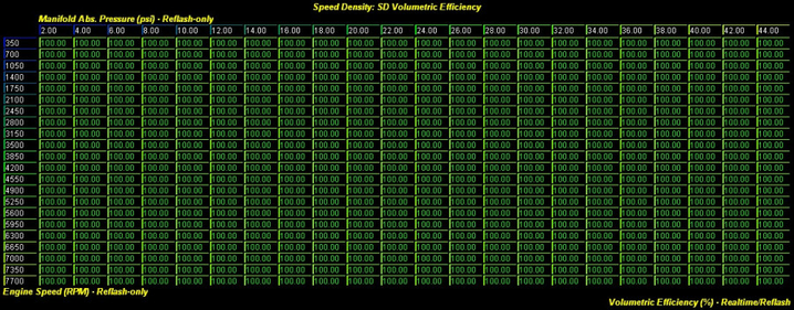
The SD Volumetric Efficiency table is the primary means by which the SD tune is accomplished. Once you have your starting values configured for this table (as described in the previous section), you can get to the actual tune. You'll need to make sure you are in SD mode (1 in the SD mode table) and the car is at operating temperature. As you hit the MAP/RPM area corresponding to a given cell, if your wideband o2 (wbo2) sensor reads richer than what the ECU is targeting, you reduce VE for that cell. If your wbo2 sensor reads leaner than what the ECU is targeting, you increase VE for that cell. You continue this process until you've dialed in as much of the VE table as you can.
As mentioned in our starting values section: On DIT engine, The SD Volumetric Efficiency (A/B Table) TGV State (0 = A Open / B Closed, 1 = A Closed / B Open) table allows you to chose which of the A and B tables is associated with TGV open and closed positions. We suggest taking advantage of realtime tuning in the SD Volumetric Efficiency A table to save time. You can tune the A table, then flip the toggle and switch table data from A to B, then tune the other TGV condition in realtime.
The final ECU fueling target can be determined via the Commanded Fuel Final monitor. This may be different at times than your primary open loop fueling table(s) or closed loop fueling target table(s) due to additional fueling compensations that come into play, such as post-start/warm-up enrichment, wall-wetting comps (EJ), and others. Also, in closed loop, the ECU is not always targeting 1.0 lambda (i.e. 14.7:1 AFR gas). The Commanded Fuel Final will account for all these changes as it is the final fueling target used to ultimately determine injector pulse width.
You should be aware of when the closed to open loop fueling transition occurs for your tune. When the transition to open loop happens, you may see a lean or rich spike when the short-term fuel trims are no longer applied if that area of VE table needs work. You can determine the closed/open loop status via the Closed Open Loop Switch monitor.
If the car has a functional and accurate front o2 sensor, you can also tune VE in closed loop via the short and long-term fuel trims (at lower boost only for factory location sensor for EJ). Simply add together the AF Correction 1 and AF Learning 1 monitors and try to get this sum as close to zero as feasible by manipulating VE. If the sum is positive, the ECU is adding fuel because of a lean condition and you will need to increase VE. If the sum is negative, the ECU is removing fuel because of a rich condition and you will need to decrease VE.
You may be tempted to simply manipulate the VE table to hit the fueling target you desire for a given MAP/RPM area regardless of the commanded fuel final (and the primary open loop fueling tables and/or closed loop fuel target tables). This method has some major downsides. First, in closed loop, the ECU will always adjust fuel trims to hit the closed loop fuel target. If those are not representative of your desired fuel targets, the car will experience more extreme trims and erratic fueling. Second, tuning this way would result in VE values that are not representative of the actual value. That is, you could not easily compare them to other tunes. It can be quite useful to compare VE tables across tunes as it gives you an idea of VE changes with different mods (and cam timing). It can also help you use those values as a starting point for new tunes for cars with similar mods. Third, making changes to fueling after completing the tune is a little easier if the VE table represents actual VE. You would simply modify the primary open loop fueling tables (and/or closed loop fuel target tables) to your new desired fuel targets.
When you've dialed in the VE tune, use the Accesstuner graphing to help to smooth the table. Generally speaking, actual VE should not drastically change with small changes in RPM and MAP and, therefore, you should not see drastic changes in VE between cells in the VE table. Smoothing the table will result in a more consistent load calculation and therefore, more consistent fueling and timing.
In addition, you will also need to estimate the areas of the VE table you were not able to hit when tuning. The values should be reasonable given the adjacent cells that were directly tuned. Also, keep in mind when estimating VE, that VE will generally increase with an increase in MAP and for RPM, it will generally follow the torque curve of the motor (with the peak VE occurring at the RPM in which peak torque occurs and decreasing on both sides of that peak).
SD Airflow Compensation (Intake Temp) Table
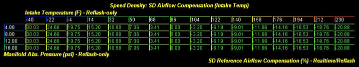
Like the VE table, the SD Airflow Compensation (Intake Temp) table is another critical component of the SD airflow calculation. In order for our SD airflow to be accurate, we not only need to know MAP, RPM, VE, and engine displacement, but we also need to know the temperature of the cylinder charge. Without this input and its corresponding correction, any given cell in our VE table would only be valid at the charge temperature in which it was tuned. Without this correction, if the cylinder charge temp dropped from our tuned charge temp, we would go lean and if it went up, we would go rich.
We have no means of directly measuring cylinder charge temperature so we have to rely on measuring intake temperature at some point as a means of estimating charge temp. Generally, the closer to the combustion chamber we measure the intake temp, the closer we'll be to the charge temp. The EJ cars do not have manifold intake temperature sensors, which would be the typical implementation for SD from the factory. Instead, these Subarus have the IAT sensor housed in the MAF sensor assembly which is located pre-turbo in the intake tract. This is the only input the factory EJ ECU has for intake temp. In the case of a car with a front-mount intercooler, the MAF/IAT assembly could be relocated post-intercooler (or an aftermarket IAT sensor installed in the same location) which would give you a more accurate representation of charge temperature. Regardless, having the ability to tweak the charge temp correction is an important component of the SD tune.
Normally, if applying the ideal gas law to estimate engine airflow, the non-linear correction factor for charge temp would be wrapped up in the ideal gas law equation. However, in order to allow the ability to tune this correction, it has to be externalized. For COBB SD, this is accomplished by first calculating SD airflow at a specific reference temperature of 86 degrees Fahrenheit. Then the SD Airflow Compensation (Intake Temp) is applied (along with the other SD compensations) to determine the final SD airflow. As you can see from the default values in the table, the 86 deg. F column has 0% correction. The default values for the rest of the columns are scaled with the ideal gas law and our reference temperature in mind. As such, this allows for a tunable charge temp correction.
What this all means is there may be scenarios where your intake temp reading may be notably different from the actual charge temp. As such, the default ideal gas law based values in this table may need to be tweaked. As you can see, the table also has a MAP axis. This allows you to come up with different sets of corrections based on MAP. This is important because MAP is one of the primary factors which can impact necessary tweaks to the table. The default values for the MAP axis are mostly in vacuum, but these can be changed as needed (axis value changes require a reflash).
One scenario in which the IAT reading may be notably different than the charge temp for the EJ is when using an IAT sensor placed before the turbo (known as a draw-through location). This is the case with the factory placed MAF housing, which also contains the IAT sensor. When the IAT sensor is pre-turbo/intercooler, the impact of the turbo and intercooler on charge temperature is not reflected in the IAT reading. Generally speaking, at very low MAP, the effect is negligible. However, as MAP increases, you may find the need to tweak the IAT correction differently based on the input temperature and MAP. Keep in mind heat soak of the IAT sensor (described below) may also be another factor you would have to account for in addition to the pre-turbo IAT reading. This is why, if you are running a front-mount intercooler, we recommend your IAT sensor be placed in a blow-through configuration (i.e. post-IC), whether than involves relocating the factory MAF/IAT assembly or wiring-in an aftermarket IAT sensor to the factory IAT input.
The other scenario in which the IAT reading may differ markedly from actual charge temp is when the IAT sensor becomes heat-soaked. What happens is the sensor itself absorbs heat from the surrounding air and intake piping and reads a temperature higher than the actual temperature of the airflow. Generally, this effect is progressively more pronounced at lower MAP/airflow and therefore you may be more likely to see it in conditions such as stop and go driving, extended idling, or a hot restart. Because the IAT reading is higher than the charge temp, this would cause the airflow/load calculation to be less than actual and you would end up going lean (as well as causing potentially more timing advance). When MAP/airflow does increase, the heat soak effect of the sensor does not instantaneously diminish, so the heat soaked reading may continue at a higher MAP for a period of time. This may present a problem if, for example, the car is subject to high loads (such as wide open throttle) soon after heat soak of the sensor sets in. This is one reason why a wideband o2 sensor and means of monitoring it in the car running SD is important, as well as the driver understanding how to recognize a problem.
There are some steps that can help partially mitigate specific heat soak scenarios. First is the use of a short-ram intake in a draw-through IAT configuration (EJ) appears to be the combo where heat soak potential is the greatest. The post-intercooler IAT sensor placement appears to have the least heat soak potential (but can still definitely occur). Second is some tweaking of the IAT comp table may help in certain cases. Generally speaking, the higher the IAT reading, the more likely heat soak of the sensor can occur. This may not always be the case, but it is something you can attempt to mitigate by increasing the airflow compensation at higher IATs (i.e. higher correction means higher airflow and more fuel). For example, you may find the car becomes progressively leaner as IATs increase above 140F. In that case, tapering the negative correction progressively (from the default values) at IATs of 140F and greater could help. Also, the effect is likely to be more pronounced at lower MAP, so plan your changes accordingly. You may want to, however, keep some of your changes at higher MAP as the heat soak effect may linger for a period in going from low MAP to high MAP. Keep in mind, though, the heat soaked IAT reading can potentially occur even at colder temps. For example, the charge temp maybe 40 deg. F and the IAT reading is 60 deg. F. This would still be a heat soak scenario (although one which would be difficult to account for) even though the temperatures are relatively mild.
SD Airflow Compensation (Coolant Temp) Table
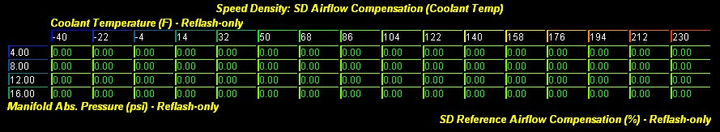
It is not necessary to tune the SD Airflow Compensation (Coolant Temp) table as far as the ideal gas law and our SD airflow calculation is concerned. As such, the default values are set to 0% across the entire table. However, you may find some circumstances where it may be useful to tweak this table for your SD tune. One example would be more extreme coolant temp readings (on the high end). You may want to increase correction at this extreme as this may mean a more likely heat soak scenario for the IAT sensor (high ECT likely means higher radiant engine heat). As described in the previous section, a heat soaked IAT sensor (relative to actual charge temp) will result in a lean condition with SD.
SD Airflow Compensation (Barometric) Table
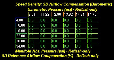
As you go up in altitude, the barometric pressure drops. The SD airflow calculation for COBB SD accounts for this change because MAP is a part of the ideal gas law calculation and therefore, as barometric pressure decreases, MAP also decreases (all else equal) and SD airflow will also decrease. However, exhaust gas backpressure also decreases as barometric pressure decreases, which can impact VE. As such, you may need to tune the SD Airflow Compensation (Barometric) table if the car is going to see notable changes in altitude. In addition to the barometric pressure axis, this table also has a MAP axis. This will allow you to tune the compensation against MAP where the effect of exhaust gas pressure on VE may vary.
Tuning SD – Miscellaneous Tables
The following are some miscellaneous SD-related tables which generally would not need to be tweaked for most SD tunes:
Load Filtering in MAF and SD Mode (EJ 2.0L/2.5L only)


The factory ECU calculates a smoothed version of load for the final load calculation. Smoothing is a means of filtering out "noise" in a value by considering the change in the current value versus the previous value. That is, it will tend to dampen larger short-term changes. The dampening effect is dependent on the smoothing factor used in the filtered calculation. The factory ECU's load smoothing factor is set up for the response characteristics of the MAF sensor which is notably different than the MAP sensor, especially during transients. As such, the load smoothing is not optimal when calculating load based on SD airflow (i.e. when the primary input is the MAP sensor) and would potentially cause tip-in/tip-out and idle issues (among others) if not accounted for.
COBB SD solves this problem by allowing for separate tunable load smoothing factors for SD and MAF mode. The smoothing factor is a value ranging from above zero to 1.0. A value of 1.0 means there is no smoothing involved and the load calculation is not manipulated. With values below 1.0, the smaller the smoothing factor, the more dampened the load will become. The Load Determination Smoothing Factor (MAF Mode) table, found under the "Speed Density" → "Miscellaneous" group, has a default value that is the same as the factory map (0.125, 0.1, or 0.09 depending on ECU). Generally, this should not be changed. The Load Determination Smoothing Factor (SD Mode) has a default value of 1.0. We have found this works best in most scenarios for SD tuning (i.e. no smoothing for load in SD mode). If, however, you are seeing load changes that are too erratic (or cause a richer than expected tip-in) and cannot be solved by further tuning/smoothing of the VE table, you may find it useful to lower the SD mode load smoothing factor. Generally, though, it should still be much higher than the default MAF mode smoothing value.
Airflow Filtering in SD Mode (DIT only)
%202018%20USDM%20WRX%20MT%20CCF.jpg?version=1&modificationDate=1566484932096&cacheVersion=1&api=v2&width=640&height=171)
The DIT factory ECU calculates a final corrected version of airflow using a complex airflow modeling scheme. This logic is not appropriate for airflow from the SD calculation and therefore, it is bypassed when SD mode is active (the final SD airflow becomes the final corrected airflow used by the ECU). COBB SD for DIT includes a means of manipulating the smoothing for the final SD airflow via the real-time tuneable SD Airflow Corrected Smoothing Factor table (found in the "Speed Density" → "Smoothing" group). Smoothing is a means of filtering out "noise" in a value by considering the change in the current value versus the previous value. That is, it will tend to dampen larger short-term changes. The dampening effect is dependent on the smoothing factor used in the filtered calculation. Higher smoothing factor values result in less smoothing (more responsive to spikes in current sensor data), while lower values result in more smoothing (less responsive to spikes in current sensor data).
MAP Determination Averaging Window (EJ 2.0L/2.5L only)
Because the MAP sensor is one of the crucial inputs to the SD airflow calculation, a collection of factory tables manipulate the final MAP value have been exposed in the software and can be found under the "Sensor Calibrations" group (see table list below):
![]()
When the MAP delta (current MAP – previous MAP) is within the averaging window of the MAP delta threshold, the ECU will use an average of the last two MAP values as follows:
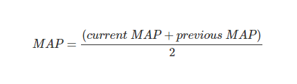
Later EJ 2.5L ECUs have two separate averaging windows that are used based on an RPM threshold (see table list above). Earlier ECUs only have a single averaging window (i.e. only a single MAP Determination Averaging Window MAP Delta Thresholds table).
Generally, these do not need to be modified for SD tuning. However, if you find MAP is too erratic (and not representative of actual changes in MAP), you may find expanding the MAP delta range in which the averaging is applied may help.
On the other side of the coin, if you find MAP is not reacting fast enough to actual changes in MAP, you may find it useful to narrow the MAP delta window.
MAP SD Smoothing Factor (DIT only)
%202018%20USDM%20WRX%20MT%20CCF.jpg?version=1&modificationDate=1566484932272&cacheVersion=1&api=v2&width=583&height=168)
The SD feature for DIT uses separate filtering capability for the manifold pressure input to the SD feature via the real-time tuneable Manifold Pressure Smoothing Factor (SD) table (found in the "Speed Density" → "Smoothing" group). This smoothing factor can be tuned without impacting any of the manifold pressure inputs of any other functions (OEM or custom) outside of the SD feature. The final SD manifold pressure can be tracked via the Manifold Abs Pressure Extended SD monitor. Smoothing is a means of filtering out "noise" in a value by considering the change in the current value versus the previous value. That is, it will tend to dampen larger short-term changes. The dampening effect is dependent on the smoothing factor used in the filtered calculation. Higher smoothing factor values result in less smoothing (more responsive to spikes in current sensor data), while lower values result in more smoothing (less responsive to spikes in current sensor data).
Generally speaking, the default smoothing factor for this table will work well for most SD tuning scenarios. However, if you find SD MAP is too erratic (and not representative of actual changes in MAP), you may find decreasing the smoothing factor may help. On the other hand, if you find SD MAP is not reacting fast enough to actual changes in MAP, you may find it useful to increase the smoothing factor.
SD Feature Activation
The SD feature set can be completely deactivated by setting the following table to zero:
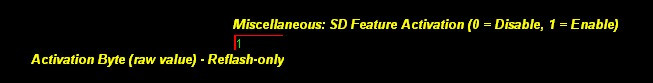
Disabling the SD feature will cause the ECU to revert back to the OEM logic for determining airflow (based on MAF sensor input). However, this is different from MAF mode in that the SD airflow will no longer be calculated and the operational mode cannot be changed to SD or Hybrid via a real-time map. SD feature deactivation should not normally be used unless you experience an SD-related bug that impacts the safe operation of the CCF/SD ECU even in MAF mode.
Tuning SD – Post-Tune Recommendations
When you feel your SD tune is complete, there are several things you should consider in order to maximize the long-term reliability of the SD tune:
- It is important your reflashed map has the same SD Mode table value as your real-time tune. For example, if you switch to an SD Mode of 1 (i.e. SD airflow) via real-time and tune the car, but do not change the SD mode from the default of 0 in the reflashed map (i.e. MAF mode), then the ECU will end up switching to MAF mode the next time the car's battery is disconnected or the ECU is reset. In addition to the SD mode, it is also important to reflash your final tune to make sure the final tune is always part of the "base" map.
- If the SD tune was completed on a dyno, it is important to drive the car under conditions it is likely to see during normal operation, verify the tune is safe, and there are no driveability concerns.
- For the EJ, it is highly recommended that a wideband o2 sensor and the in-car gauge is installed in the car running SD (or wired into a CCF custom input). For both EJ and DIT, it is important the owner/driver of the car is instructed on what, generally speaking, is a normal O2 sensor reading for the tune and given operating conditions, especially at high load.
- The owner/driver of the car needs to be instructed about the potential for a heat soaked IAT sensor and under what conditions this is likely to occur (extended idling, hot soaked re-start, etc). It is important the owner/driver understands putting the car immediately under heavy load when a heat soaked IAT sensor may be a possibility that should be avoided when running SD. Instead, under these conditions, allow the car to get moving without getting heavily into boost for at least a few minutes before putting the car under heavy load. For EJ, a wideband o2 sensor with in-car gauge (or wired into a CCF custom input) can help here as a heat-soaked IAT sensor will generally cause the fuel reading to be leaner than expected.
- The owner of the car also needs to understand practically any engine mod that impacts airflow in any way may require a re-tune or tweaking of the VE table for cars running SD. This is important as even seemingly minor mods that a MAF sensor-based tune would have no problem accounting for, might cause a significant enough change in VE, that there could be fueling and load issues for SD.
Tuning SD – Additional Topics
Recommended Calibrations for Aftermarket IAT Sensors
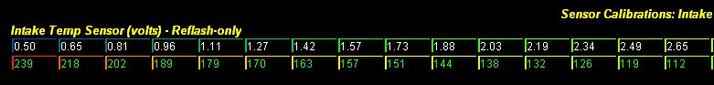
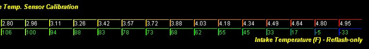
When an aftermarket IAT sensor is installed, you will need to tune the IAT sensor calibration which will be different from an aftermarket sensor as compared to the factory IAT sensor. This is done via the Intake Temp. Sensor Calibration table (EJ) in the "Sensor Calibrations" group.
The following shows the recommended IAT scaling for the GM and AEM aftermarket IAT sensors (each screenshot shows one half of the table). Keep in mind both the axis values (top row) and data values (bottom row) change in this case. WARNING: These calibrations are provided for your convenience only and do not represent an endorsement for or against any particular product. The manufacturer's specifications can change at any time. It is important you verify the sensor calibration you are going to use before tuning SD.
Because DIT cars have a manifold temp sensor, there's not typically an advantage to wiring in an aftermarket IAT sensor in its place. However, if you wish to do so anyway, only the manifold intake temp input can be hi-jacked for DIT SD and scaling for that sensor is accomplished via the Intake Temp. Sensor Calibration (Manifold) table. This DIT table is slightly larger than the EJ 2.5L table shown below and modifying the manifold sensor volts axis for DIT also modifies the volts axis for the Intake Temp. Sensor Calibration (Pre-Turbo) calibration table (this axis is shared between the two tables). As such, the temperature values for the pre-turbo table will have to be modified appropriately or the Intake Temp. Chosen Source (0 = Pre-Turbo Sensor (MAF), 1 = Manifold Sensor) table (under "COBB Custom Features" → "Intake Temp. Source Selection") will have to be set to 1 (overriding the pre-turbo intake temp with manifold temp).
Calibrations for Aftermarket MAP Sensors
When an aftermarket MAP sensor is installed, you will need to set up the MAP sensor calibration appropriately. This is done via the MAP Sensor Calibration (Multiplier) and MAP Sensor Calibration (Offset) tables in the "Sensor Calibrations" group. The boost reading (via Accesstuner software or Accessport) should then be compared to an external boost gauge to verify accuracy before tuning SD. The recommended calibrations for some of the most popular aftermarket MAP sensors are shown below. WARNING: These calibrations are provided for your convenience only and do not represent an endorsement for or against any particular product. The manufacturer's specifications can change at any time. It is important you verify the sensor calibration you are going to use before tuning SD.
NOTE: Values below are shown in "standard units" (psi). Make sure the "Standard Units" selection is in a checked state in Accesstuner before entering values (Found in "Edit" → "Configure Options" → "Display"). You can uncheck this option after entering values (if you desire non-standard units).
- COBB 4 bar (Part # 812300) –> MULTIPLIER = 14.504 psi , OFFSET =-7.252 psi
- AEM 3.5 bar (Part # 30-2130-50) –> MULTIPLIER = 12.5 psi , OFFSET =-6.25 psi
- AEM 5 bar (Part # 30-2130-75) → MULTIPLIER = 18.75 psi, OFFSET = -9.375 psi
- GM 3 bar (Part #12223861) → MULTIPLIER = 8.94 psi, OFFSET = 0.1604 psi
- OmniPower 3 bar (Part #MAP-STI-3BR) → MULTIPLIER = 9.122 psi, OFFSET = 0.164 psi
- OmniPower 4 bar black (Part #MAP-STI-4BR) → MULTIPLIER = 12.086 psi, OFFSET = 0.169 psi
- OmniPower 4 bar red (Part #MAP-STI15-4BR) → MULTIPLIER = 12.931 psi, OFFSET = -2.905 psi
Forcing Open Loop Fueling
In some cases, you may find it more straightforward to temporarily force the ECU into full-time open loop fueling when tuning the VE table. This can be accomplished by the following procedure:
- Change the Primary Open Loop Fueling Min. Activation table(s) (found under the "Fuel Tables" → "Open Loop (Primary)" group) to 14.7:1 AFR (or 1.0 lambda for non-standard units).

- For the 2017+ STi, change the Closed/Open Loop Transition Main (Closed Loop Fueling Target)(Closed Loop Switch Lean Threshold) table (found under the "Fuel Tables" → "Closed/Open Loop Transition" → "Transition Thresholds (Main)" group) to 25.00:1 AFR (or 1.70 lambda for non-standard units).
- For the DIT WRX 17+, change the Closed to Open Loop Transition Final Decision Rich Threshold (Closed Loop Fueling Target) table (found under the "Fuel Tables" → "Closed/Open Loop Transition (Primary Fuel Activate)" → "Transition (Final Decision)" group) to 22.303:1 AFR (or 1.517 lambda for non-standard units)
- In the Primary Open Loop Fueling... table(s), change the 14.7:1 AFR cells (or 1.0 lambda cells) to the next richest value. For example, change 14.7:1 to 14.59:1 AFR (or 1.0 lambda to 0.99 lambda).
- Change the Closed to Open Loop Delay(s) table (found under the "Fuel Tables" → "Closed/Open Loop Transition" group) to zero. If the ECU in question has multiple cells for this table, make sure every cell is zero.
- Save the map and reflash the map to the car.
- Verify the ECU remains in open loop full-time by viewing or logging the Closed Open Loop Switch monitor in the Accesstuner software.
It is not recommended you run a full-time open loop operation after the tune is complete. This is because certain scenarios with SD that would result in fueling errors, such as a heat soaked IAT sensor or changes in VE due to mechanical/aging issues, can be partially mitigated by short-term fueling corrections (and potentially long-term fuel trims) when closed loop operation is active.
Long-Term Fuel Trims (EJ 2.0L/2.5L only)
You may find it more optimal to manipulate how the long-term fuel trims are determined when running SD (and in some cases, for MAF mode as well). The long-term fuel trims are determined based on patterns of short-term correction. They are calculated and applied across four airflow ranges. These ranges are determined by the A/F Learning #1 table (under the "Fuel Tables" → "A/F Learning" group). The following is an example:
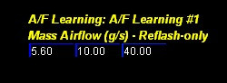
As you can see, there are three values to this table. The airflow ranges are determined from these values as follows (given the example):
Range A: 0-<5.60 g/s
Range B: 5.60-<10.00g/s
Range C: 10.00-<40.00 g/s
Range D: 40.00+
The "D" range is of particular importance because any correction learned in closed loop for this range is not only applied in closed loop but also open loop as well since it is applied at any airflow above its threshold (in this example 40+ g/s). This can be problematic if the correction is extreme and is removing fuel (i.e. correction is negative). For example, if the "D" range value was -5%, then fueling will be leaner by 5% in closed loop above 40 g/s (in this example) and 5% leaner in open loop, including wide open throttle. That is, the ECU assumes the correction learned in the "D" range is needed in open loop as well, which may not always be the case.
You can disable the "D" long-term fuel trims via the A/F Learning #1 Modify Airflow Limit (Max) table in the "Fuel Tables" → "A/F Learning" group. This is accomplished by setting this table's value to less than the "D" range threshold you are using (in this example, less than 40 g/s):

Additionally, you can also modify the allowable limits for A/F Learning #1 via the A/F Learning #1 Limits (Min/Max) table (also under the "Fuel Tables" → "A/F Learning" group):

You can view/log long-term fuel trims via the AF Learning 1 monitor. This shows the currently applied long-term fuel trim. You can also view all four ranges via the AF Learning 1 Range A, …Range B, …Range C, and …Range D monitors or by live connecting to the ECU and viewing the real-time A/F Learning #1 table.
Long-Term Fuel Trims (DIT only)
You may find it more optimal to manipulate how the long-term fuel trims are determined when running SD (and in some cases, for MAF mode as well). The long-term fuel trims are determined based on patterns of short-term correction. They are calculated and applied across ten load/RPM ranges outside of idle. These ranges are determined by the A/F Learning #1 (Non-Idle) table (under the "Fuel Tables" → "A/F Learning" group). The following is an example:
%202016%20USDM%20WRX%20CVT%20-%20.jpg?version=1&modificationDate=1566484932477&cacheVersion=1&api=v2&width=667&height=229)
When referencing the various tables and monitors involved, the cells in the A/F Learning #1 (Non-Idle) table will be labeled as follows:
A1 | B1 | C1 | D1 | E1
A2 | B2 | C2 | D2 | E2
The minimum and maximum A/F Learning #1 values for the non-idle table can be tuned via the following tables:
%202018%20USDM%20WRX%20MT%20CCF.jpg?version=1&modificationDate=1566484932654&cacheVersion=1&api=v2&width=390&height=73)
Full-time Closed Loop (DIT only)
DIT cars can be tuned to allow for full-time closed loop operation (see "FORCE FULL-TIME CLOSED LOOP" section at the link below). This is generally ideal for SD as the ECU will continue to modify fuel trims in an attempt to hit the fueling target, even at high load. In a scenario, for example, where the SD calculation may not be as accurate (such as a heat-soaked manifold temp sensor), full-time closed loop can mitigate (to a point) fueling errors that may otherwise be problematic.
Subaru Accesstuner DIT Tuning Guide Supplement
Rear Oxygen Sensor Influence On Fueling (EJ 2.5L and DIT only)
In addition to the front oxygen sensor, Subarus also employ a rear oxygen sensor in order to monitor the exhaust stream after the catalytic converters and cause fuel trimming based on that data. The tables related to rear oxygen sensor based trimming can be found under the "Fuel Tables" → "Closed Loop Target" group (or "Fuel Tables" → "Closed Loop Target" group). The following is a list of each table (note: the assortment of tables varies by ECU):
- Closed Loop Fueling Target Compensation (Rear O2) Limits (Max) – This is the max closed loop fueling target adder based on rear o2 input. The factory default is set to an extreme value so the limit never comes into play.
- Closed Loop Fueling Target Compensation (Rear O2) Limits (Min) - This is the min closed loop fueling target adder based on rear o2 input. The factory default is set to an extreme value so the limit never comes into play.
- A/F Learning #3 Limits... - These are the max and min values for the long-term fuel trim based on rear o2 input. The factory defaults are set to extreme values so the limits never come into play.
- A/F Correction #3 Limits... – These are max and min values for the short-term fuel trim based on rear o2 input. The factory defaults are set to extreme values so the limits never come into play.
- A/F Correction #3 Adder... – These are the adders to the short-term rear o2 based fueling correction.
Cam Timing (AVCS) Tuning Changes and Effect on VE (EJ 2.5L and DIT only)
Most tuning changes are not going to impact VE. For example, once you have your VE table dialed in, you can generally make changes to ignition timing, fuel targets, and boost tuning without needing to revisit the VE table due to those changes. However, there is one exception. That is changes to cam timing (i.e. Subaru's AVCS). Cam timing changes can definitely impact VE and will likely require you to tweak the VE table as a result. Because the AVCS table(s) have load as one of the axes, it may also be useful to keep these tables relatively smooth (i.e. no drastic changes between cells). Otherwise, when attempting to dial-in the VE table, large changes in cam timing with small changes in load/RPM will change actual VE and you may end up with feedback loop of sorts which makes it more difficult to tune.
Tuning MAF Mode
In MAF mode (i.e. a value of 0 in the SD mode table), MAF sensor-based tuning is the same with COBB CCF/SD ECU as it is with the non-CCF/SD ECU. That is, tuning for specific intake hardware is accomplished via the MAF Calibration table. The only difference is the CCF/SD ECU will calculate SD airflow (and other SD-related values) while still in MAF mode, even though those values are never used in determining airflow. This allows you to, for example, get a starting tune ready for the SD VE table while still running the car in MAF mode.
Tuning Hybrid Mode
Overview
In Hybrid mode (i.e. a value of 2 in the SD mode table), you are simply allowing the SD ECU to switch between MAF mode and SD mode (and vice versa) based on a series of specific thresholds for MAP, RPM, throttle position (TPS), and MAF voltage (MAFv). In addition, you can also control the behavior of the switching as well as the speed of the transition.
Hybrid Mode - Uses
There are a handful of reasons why hybrid mode might be a better choice than running pure SD mode. The following are some examples:
- If the car runs well on the MAF sensor-based tune but maxes out the MAF sensor on the high end, the hybrid mode could be used to switch to SD to avoid maxing out the sensor. Running hybrid mode, in this case, would reduce the time and effort it would take to get the car to a well-tuned state when compared to a pure SD tune.
- If the car has a big MAF set-up and runs well on the high end, but poorly on the low end (i.e. idle/cruise), the hybrid mode could be used to run SD on the low end and MAF on the high end to mitigate these issues. This would also reduce the time and effort to finish the car's tune vs. a pure SD tune.
Hybrid Lower/Upper Mode
The first thing to decide is what mode will be used on the lower end and what mode will be used on the upper end. This will be either MAF on the lower end and SD on the upper end or MAF on lower and SD on upper. The MAP, RPM, throttle and/or MAF voltage thresholds determine the switching from the lower to upper mode (and vice versa). So, for example, if you wanted to switch to SD when one (or more) of these tunable thresholds are exceeded, then you would want SD on the upper end and MAF on the lower end.
Whether lower/upper is MAF/SD or SD/MAF is configurable via the following table:

If this table's value is set to 0 (the default value), then MAF mode is used below the threshold(s) and SD mode is used above the threshold(s). If it is 1, then SD mode is used below the threshold(s) and MAF mode above.
Hybrid Threshold Switching Behavior
You can also decide how the switching from upper to lower (and vice versa) will work based on the thresholds. That is, how many of the thresholds must be exceeded to switch to the upper mode and how many values must fall below their corresponding thresholds to switch to the lower mode. This is determined by the following table:

For example, if this table's value is 0 (the default value), then the following has to be met to switch modes:
- Switch from lower to upper mode: any single value exceeds its corresponding threshold.
- Switch from upper to lower mode: all values must fall below their corresponding thresholds (less the corresponding hysteresis)
If this table's value is 1 then the following has to be met:
- Switch from lower to upper mode: all values must exceed their corresponding thresholds
- Switch from upper to lower mode: any single value falls below its corresponding threshold (less the hysteresis).
Hybrid Thresholds Overview
For the upper mode, a threshold is exceeded if the value in question is greater than the threshold. For the lower mode, the value is considered to have dropped below the threshold if it is less than or equal to the threshold less its hysteresis (threshold – hysteresis). The threshold table listing is shown below:
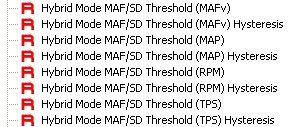
For example, if your MAFv threshold is set to 3.5v and the MAFv hysteresis is 0.25v, then the threshold is exceeded if MAFv is greater than 3.5v and MAFv has dropped below the threshold when MAFv is less than or equal to 3.25 v (3.5v – 0.25v). The reason for the hysteresis is to avoid rapid transitions between MAF and SD modes if the value were to hover around the threshold.
Hybrid Threshold Individual Deactivation
All four thresholds do not have to play a role in determining the MAF and SD mode transitions. You can remove specific thresholds from the decision process by setting those threshold(s) to unachievable values (which will depend on the threshold switching behavior explained above).
If the switching behavior is 0 (upper switch = single, lower switch = all), then setting any threshold to an extremely high value which will never be achieved, will remove it from the decision process. For example, you could raise the RPM threshold to an unachievable value of 10000 RPM and RPM would never play a role in the switching.
If the threshold switching behavior is 1 (upper switch = all, lower switch = single), then setting any threshold to a value which will always be exceeded, will remove it from the decision process. For example, you could set the RPM threshold to 0 RPM and RPM would never play a role in the switching.
Hybrid Transition Blending
When the decision to switch from MAF to SD mode (or vice versa) is made, the final airflow value will not abruptly switch from the airflow calculation of one mode to the other. Instead, over a short period of time, the final airflow will be calculated as a blend between the on-going airflow calculation in the old mode and the on-going airflow calculation in the new mode, with the bias increasing from old to new as the ramping process proceeds. This allows for a smoother airflow transition between modes (and therefore smoother fueling/timing transition), especially where the SD-based airflow and MAF sensor-based airflow calculations may be somewhat farther apart from one another.
The ramping is determined by the hybrid map ratio. This multiplier can range from 0 to 1 and determines the blending of the old and new airflow values as follows: final airflow = (SD airflow * map ratio) + (MAF * (1 - map ratio)). If the hybrid map ratio is 0, then the final airflow is entirely based on MAF (i.e. the MAF sensor-based airflow). If is it 1.0, then the final airflow is entirely based on SD airflow. Any value in-between is a blend of both MAF and SD airflow with the bias dependent on the value.
When the decision to move from MAF to SD mode is made, the hybrid map ratio, which would begin at 0 in this case, would be incremented by a specific value (see tables below). The hybrid map ratio would continue to be incremented as long as the decision to switch to SD remained and, over a short period of time, the map ratio would reach 1.0 and SD airflow would entirely be used. The opposite is the case in moving from SD to MAF mode. The map ratio would begin at 1.0 and would be decremented by a specific value as long as the decision to switch to MAF remained and, over a short period of time, the map ratio would reach 0 and MAF would entirely be used.
The speed at which the ramping process occurs (i.e. the map ratio adder) is dependent on the following tables:


As you can see from the tables above, the speed at which the switch occurs can be tuned separately for MAF to SD and SD to MAF. For MAF to SD, higher values in this table increase the speed of the blended transition, while lower values decrease the speed. For SD to MAF, the opposite is true.
Tuning Hybrid Mode – Post-Tune Recommendations
If the hybrid tune was completed on a dyno, it is important to drive the car under conditions it is likely to see during normal operation to verify the safety of the tune and the hybrid switching occurs as intended. Additionally, for the SD part of the tune, the recommendations outlined in the "Tuning SD –Post-Tune Recommendations" section earlier in this document should also be considered.
How to Monitor the Tune
The CCF/SD ECU includes specific monitors for the SD feature (shown below by ECU type). These will be useful in the tuning process as well as verifying/monitoring the tune once it is complete. See the Subaru Custom Monitor List for descriptions of each monitor.
EJ 2.0L CCF
- Calculated Load MAF SENSOR BASED
- Mass Airflow TABLE
- SD Engine Displacement
- SD Hybrid Thresh Flag
- SD Load POST COMP
- SD Load PRE COMP
- SD Mode LOAD
- SD VE Estimated MAF
- SD VE COMMANDED
- SD to MAF Hybrid Ratio
- SD MAF Load Smoothing Factor
- SD MAF Pre Final Airflow
- SD MAF Pre Final Load
EJ 2.5L CCF/SD
- Mass Airflow TABLE
- SD Airflow POST COMP
- SD Airflow PRE COMP
- SD Hybrid Thresh Flag
- SD Mode AIRFLOW
- SD VE Estimated MAF
- SD VE COMMANDED
- SD to MAF Hybrid Ratio
- SD MAF Load Smoothing Factor
- SD MAF Pre Final Airflow
DIT CCF Gen2
- Manifold Abs Pressure Extended SD
- Mass Airflow Corrected FINAL
- Mass Airflow Corrected OEM
- Mass Airflow Corrected SD
- Mass Airflow TABLE
- SD Airflow POST COMP
- SD Airflow PRE COMP
- SD Hybrid Thresh Flag
- SD Mode AIRFLOW
- SD VE B to A Map Ratio
- SD VE C to A B Map Ratio
- SD VE Estimated MAF
- SD VE Adder Map Ratio
- SD VE COMMANDED
- SD to MAF Hybrid Ratio
SD Airflow Math
This section describes the math behind the COBB SD airflow calculation which is based on the ideal gas law. It is not necessary to understand this math in order to tune SD, but some may find it interesting.
Ideal Gas Law – Introduction
The ideal gas law is an equation that governs the relationship between the pressure, volume, amount and temperature of an "ideal" gas:
P = Pressure
V = Volume
n = Number of Moles (i.e. amount)
R = Gas Constant
T = Temperature
We want to solve for the amount of gas:
Our "ideal" gas is quite simply the air being ingested by the engine. For our purposes, we want to know the mass of air entering the engine. We can determine the mass of air by using a constant that dictates the mass (in grams) per mole of air (i.e. the molar mass of air, which we'll call MMA):
Because of n = PV / RT, we can express this as:
Ideal Gas Law – Real-World Inputs
Given the above equation, we need input data for pressure (P), volume (V), and temperature (T). Given our engine scenario, these inputs would be determined as follows:
P = Pressure = Manifold absolute pressure (MAP) as determined by the MAP sensor.
V = Volume = Displacement of the engine (in liters).
T = Temperature = Cylinder charge temperature in Kelvin as estimated by the intake air temperature (IAT) sensor. The temperature in Kelvin can be determined as follows: IAT Celsius + 273.15
Let's rename the symbols used for these inputs so they are more appropriate for our engine example:
MAP = P
DISP = V
IAT = T
The constants R and MMA are determined as follows:
R = ideal gas constant (dependent on pressure units used). R = 1.205912 for MAP in psi
MMA = Molar Mass of Air Constant =28.97 g/mole
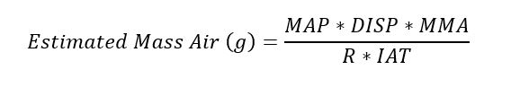
Ideal Gas Law – Volumetric Efficiency
The above equation is only valid for our engine example if volumetric efficiency is always 100%, which is obviously not the case. We must, therefore, add VE as a correction factor.
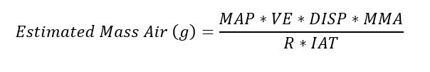
Ideal Gas Law – Mass Airflow
To determine the air entering the engine per unit of time, we add RPM as an input. Because the crankshaft rotates 720 degrees (i.e. two revolutions) for a full stroke, the number of times air is entering the cylinders per second is given by:
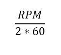
We combine the above with our mass air equation to get, ultimately, an estimated mass air in grams/second:
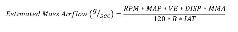
Ideal Gas Law – SD Reference Airflow
The non-linear charge temp correction is inherent to the equation above in determining the estimated airflow. However, it would be useful to be able to tweak the charge temp correction because our IAT sensor input may not always be exactly representative of the actual charge temp. This is highly dependent on the placement of the IAT sensor for a given car.
To allow for tweaking of the charge temp correction, the SD ECU first calculates a reference SD airflow using a constant for charge temp (30 deg. C, 86 deg. F). Then the IAT table correction is applied to the reference value. The default values of the IAT table are set-up with the ideal gas law in mind given our reference temperature.
Consider the following example:
MAP = 24.7 psia
RPM = 3000
VE = 0.8 (i.e.80%)
DISP = 2.5 liters (configurable table value in software)
MMA = 28.97 g/mol
IAT = 303.15 Kelvin constant (our reference temp of 30 C)
R = 1.205912 (MAP in psi)
So, the reference airflow is calculated as follows:
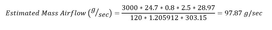
SD Final Airflow
We have calculated the SD reference airflow above. However, this airflow is only valid at our given reference temp of 86 degrees F. We must apply the IAT compensation which, with the default values in the tables, follows the ideal gas law the same as if we had originally plugged the current IAT value into the estimated mass airflow equation that was first described in this section. Let's assume that the current IAT is 122 degrees F. Looking at our IAT compensation table:
We see the table calls for -6.19% correction at 122F IAT. We can convert -6.19% to a multiplier of 0.9381 ((x+100)/100). From our reference airflow example, we calculated a reference airflow of 96.18 g/sec. We apply the IAT correction from our table as follows:
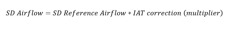
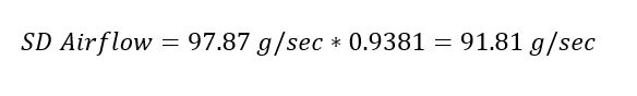
If we plug in the IAT of 122F (323.15 Kelvin) into the original estimated mass airflow equation given our current example, we end up with the same post-comp SD airflow:
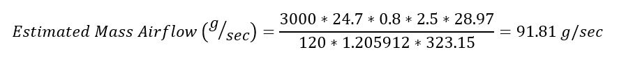
We end up with the same airflow calculation either way, but our "external" IAT compensation table allows us to tweak it in cases where the IAT input may not be representative of the actual charge temp. Our final SD airflow is determined after the ECT and barometric compensations have also been applied.
Estimated VE Calculation
The SD ECU has the SD VE Estimated MAF monitor which allows you to determine an estimate of VE if you have a properly installed, functioning, and calibrated MAF sensor in the car. The math for estimating VE is simply solving for VE in the estimated mass airflow equation given above. We are using the mass airflow as determined by the MAF sensor and the MAF Calibration table as an input to our estimated VE calculation:
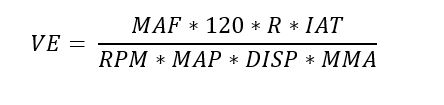
Let's take the previous example and solve for VE given our previous estimated MAF of 91.81 g/sec:
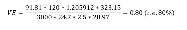
As you can see, we end up with the same VE calculation as used in the original estimated mass airflow example.
Appendix – Aftermarket IAT Sensor Install (EJ 2.0L/2.5L Only)
The following describes how to install an aftermarket intake air temp (IAT) sensor by modifying the factory wiring harness. This information is applicable to the 2002-2012 WRX and 2004-2012 STi:
- Locate and unplug your factory MAF sensor wiring harness.
- For GD Subarus (2002-2007 WRX and 2004-2007 STi), cut the Brown and Green/Red wires of the factory wiring harness so you have a suitable length.
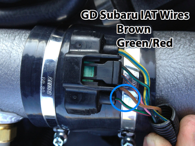
- For GR Subarus (2008-2012 WRX and STi), cut the Yellow/Red and Yellow/Blue wires of the factory wiring harness so you have a suitable length.
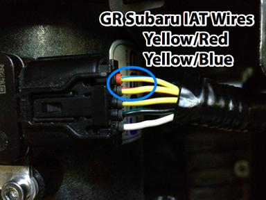
- Strip and solder together the two wires of the aftermarket IAT sensor pigtail and the engine wiring harness.
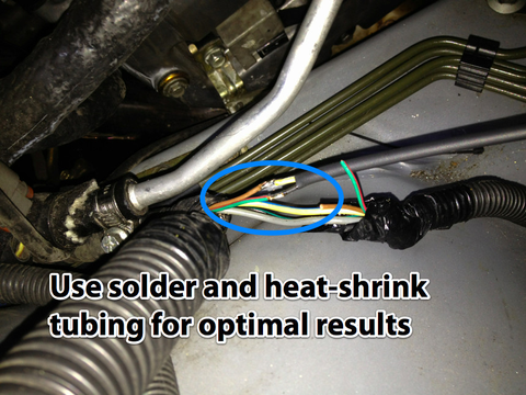
- Plug the MAF sensor harness back in (if MAF sensor is not being removed).
- Modify the "Intake Temp. Sensor Calibration" table in the Accesstuner software (under "Sensor Calibrations" group) so the appropriate calibration is achieved for your aftermarket IAT sensor. Note: Recommended calibrations for some aftermarket IAT sensors can be found in the "Tuning SD – Additional Topics" section earlier in this document.
- Save your map and reflash to car.
- Before tuning, verify the new IAT sensor is reading properly by monitoring Intake Temp via the Accesstuner software or the Accessport.
Copyright 2024 © COBB Tuning Products LLC. All Rights Reserved. | www.cobbtuning.com