7C1550 - COBB GTR Silicone Hose (Hardpipe) Kit [Discontinued]

7C1550 – COBB Tuning R35 Silicone Hose Kit
2009-2015 GTR
Congratulations on your purchase of the COBB Tuning R35 Silicone Hose Kit! The following instructions will assist you through the installation process. Please read them BEFORE beginning the install to familiarize yourself with the steps and tools needed. If you feel you cannot properly perform this installation, we HIGHLY recommend you take the vehicle to a qualified and experienced automotive technician.
Table of Contents
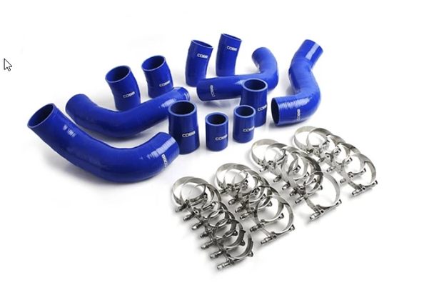
Parts List
- 2 Post MAF Hose
- 1 (each) LH and RH Hot Hose
- 1 (each) LH and RH Cold Hose
- 2 Upper Hose
- 2 Throttle Body Hose
- 2 Turbo Inlet
- 8 T-Bolt Clamp GTR74
- 8 T-Bolt Clamp GTR81
- 2 Stainless Clamp 40mm
- 2 Stainless Clamp 44mm
- 1 Metal License Plate Frame
Tools Needed
- Phillips head screwdriver
- Flathead screwdriver
3/8" ratchet
3/8" 10mm socket
3/8" 12mm socket
3/8" 8mm socket
3/8" 12" extension
3/8" 6" extension
- 10mm Box End Wrench (Ratcheting preferred)
- Needle Nose Pliers
- Silicon Spray (optional to assist in hose installation.
Bumper/Undertray Removal
- Using an 8mm wrench unhook the battery's negative terminal.
- Safely and securely raise the car on a lift or jack stands and remove the front wheels.
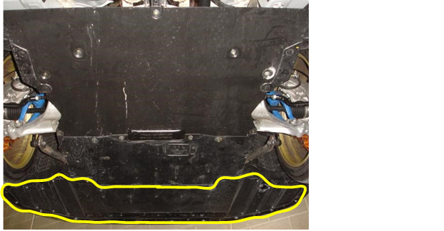
- The front bumper will be removed along with the under tray as one piece. Move underneath the car and remove the ten plastic fasteners, two 10mm bolts, and two 12mm bolts
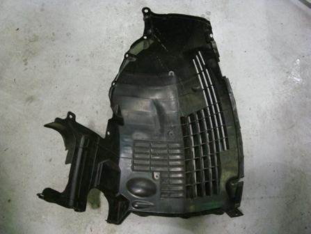
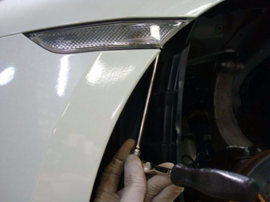
- You will now need to remove the front portion of both left and right side inner fender liners by removing the one screw and nine plastic fasteners per side. Make sure to collect all of the hardware so that you do not kick it around as you are working in the vehicle.
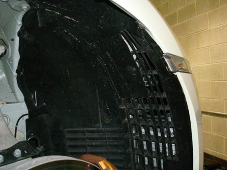
- With the fender liners removed you may now access and remove three 10mm bolts on each end of the bumper. You will also need to disconnect both side market lights
- Move to the engine bay and remove the plastic radiator cover by removing the eight plastic fasteners.
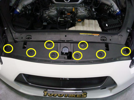
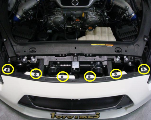
- Now remove the six plastic fasteners underneath the radiator cover.
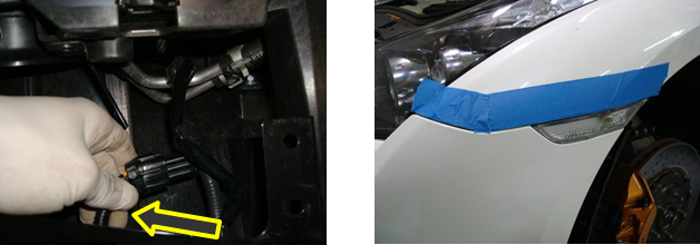
- Disconnect the connector that goes to the airbag sensors in the front bumper (JDM only) at this time you may also want to apply protective tape along the front fenders (as pictured below) to prevent them from being damaged while removing and installing the front bumprs.
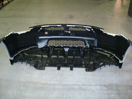
- You should now be able to remove the entire front bumper and under tray as one piece.
Stock Intercooler Pipe Removal and COBB Silicone Hose Installation
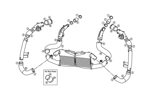
- You can go about replacing the stock rubber intercooler hoses in many different ways. We recommend you replace one side of the motor at a time starting from the throttle body and working your way down. We do not recommend you tighten any of the t-bolt clamps until all of the silicone hoses are installed. This will allow you to fine tune the fitment by rotating the silicone one piece at a time until everything fits nicely. The diagram on the right will show you which silicone piece goes where and what size clamps to use.
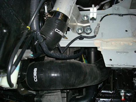
- You can align the t-bolt clamps in several different positions; some may work better than others. When installing the t-bolt clamps always assume that the possibility of the pipes blowing off exists and install them in a way that will be accessed easily, with minimal work involved. Here are a few pictures that show the orientation in which we have installed the clamps with the best fitment for future adjustments/tightening.
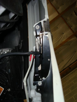
- NOTE: The first picture is of the right side upper intercooler pipes. Make sure that the t-bolt clamps at the throttle body are rotated down enough that they have sufficient room to clear the hood while the motor twists under acceleration and deceleration.
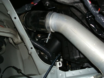
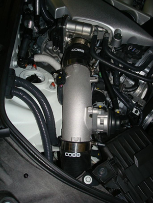
- NOTE: The first picture is of the right side upper intercooler pipes. Make sure that the t-bolt clamps at the throttle body are rotated down enough that they have sufficient room to clear the hood while the motor twists under acceleration and deceleration.
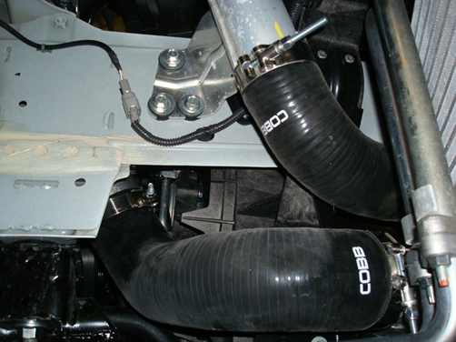
- The only way to easily access the t-bolt clamps when installing the lower intercooler pipes is to remove the inner fender liner. With the stock lower intercooler pipe removed you will want to loosen the 12mm bolt that secures the cast aluminum lower intercooler pipe and replace the small stock rubber hose on the turbo outlet with the silicone replacement. Make sure that the top clamp on the upper pipe is rotated inward enough to clear the fender liner when it is reinstalled.
- The best way to access the clamp that secures the intercooler pipe to the top of the intercooler is to remove the front bumper. Make sure that you get this one nice and tight because you don't want to have to remove the bumper again if it comes off. During this step, it may allow for more room if you remove the four plastic fasteners that attach the ducting to the oil cooler and remove it..
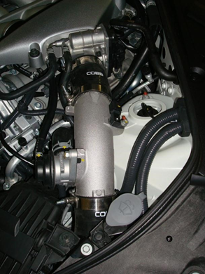
- The left side of the upper intercooler pipe clamps will be installed in the same orientation as the right side. Refer to steps 2 and 3 for specific installation notes.5. The left side of the upper intercooler pipe clamps will be installed in the same orientation as the right side. Refer to steps 2 and 3 for specific installation notes.
- The lower intercooler pipe clamps will be oriented the same as the lower right side clamps with the exception of the clamp that secures the intercooler pipe to the turbo outlet. We’ve found it easier to access this clamp from inside the engine bay rather than through the fender well. It also makes it easier to access if it comes off rather than pulling the wheel and fender liner.
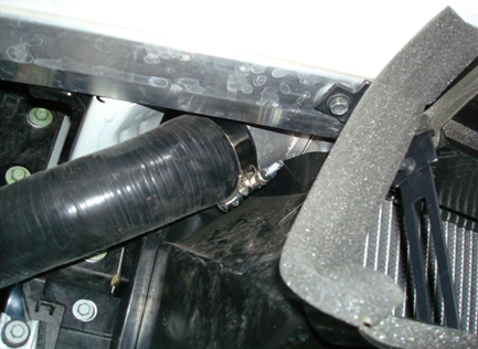
- This is the clamp that secures the intercooler pipe to the left side turbo outlet as viewed from above the engine bay. Make sure that the clamp is rotated properly so that it does not interfere with the lower radiator hose.
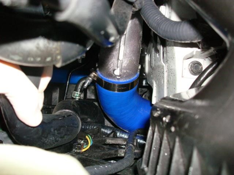
- This is the clamp that secures the intercooler pipe to the left side turbo outlet as viewed from above the engine bay. Make sure that the clamp is rotated properly so that it does not interfere with the lower radiator hose.
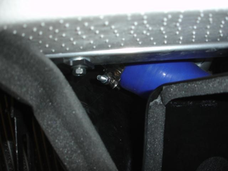
- This is the clamp that secures the intercooler pipe to the top left intercooler outlet. Once again, make sure this one is tight because it will require removing the entire front bumper to reinstall if it comes off.
- Now take several minutes to go over and double check that all of the clamps are securely tightened and that they are all properly oriented and do not interfere with any bodywork, hoses, wire harnesses, etc.Start the car and warm it up making sure that the car has a stable idle. If you find the idle becomes inconsistent or fluctuates this may be a sign of a boost leak or post MAF leak, recheck all fittings and connections until the problem has been located.Testing the intake and charge piping with a pressurizing smoke machine is highly suggested if you have access to one.
- Reinstall the bumper, undertray, fender liners and wheels in the reverse order in which they were removed.
- Go out and enjoy!
Helpful Links
Contact Us:
COBB Customer Support
Web Support and Tech Articles: COBB Tuning Customer Support Center
Email: support@cobbtuning.com
Phone support available 9am to 6pm Monday-Thursday. 9am to 4pm Friday (CST)
866.922.3059
return to www.cobbtuning.com
Copyright 2023 © COBB Tuning Products LLC. All Rights Reserved. | www.cobbtuning.com