9C1250 - COBB R35 GT-R Adjustable Sway Bar Kit [Discontinued]
- Brandyn Mowat
- Former user (Deleted)

9C1250 - COBB R35 GT-R Adjustable Sway Bar Kit
2009 - 2012 GT-R
Congratulations on your purchase of the COBB Tuning GT-R Adjustable Sway Bar Kit! The following instructions will assist you through the installation process. Please read them BEFORE beginning the install to familiarize yourself with the steps and tools needed. If you feel you cannot properly perform this installation, we HIGHLY recommend you take the vehicle to a qualified and experienced automotive technician.
Table of Contents
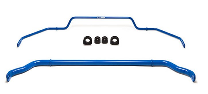
Parts List
- Front 35mm 2-way Adjustable COBB Sway Bar
- Rear 16mm 5-way Adjustable COBB Sway Bar
- Front Set of Greased Urethane Bushings
- Rear Set of Greased Urethane Bushings
Tools Needed
3/8" 10mm socket
3/8" 12mm socket
3/8" 14mm socket
- (2) 14mm combination wrenches
- 17mm combination wrench
- 19mm combination wrench
3/8" 12" extension
3/8" 6" extension
- 3/8" ratchet
- Torque Wrench
- Trim removal tool
Undertray Removal
- Securely lift and support vehicle.
- Remove the four rubber caps to expose the 10mm bolts and remove those bolts using an extension along with the 10mm socket.
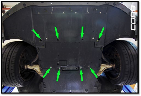
- Remove the four additional 10mm bolts towards the rear of the undertray
- Remove the eight plastic fasteners along the outer perimeter of the under-tray using the trim tool.
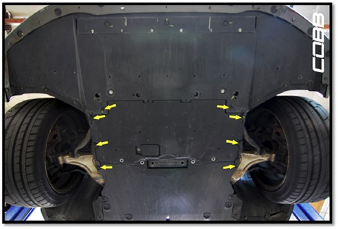
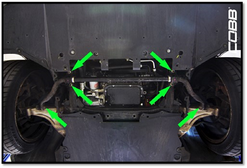
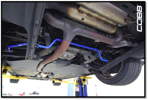
- The under-tray should now be able to slide out, exposing the location of the front sway bar.
Front Sway Bar Removal
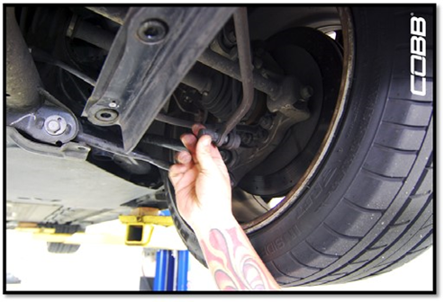
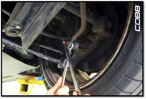
- Remove the 17mm nut from the end link using the 17mm combination wrench. Use a 19mm wrench to hold the opposite side of the end-link to prevent it from spinning under torque.
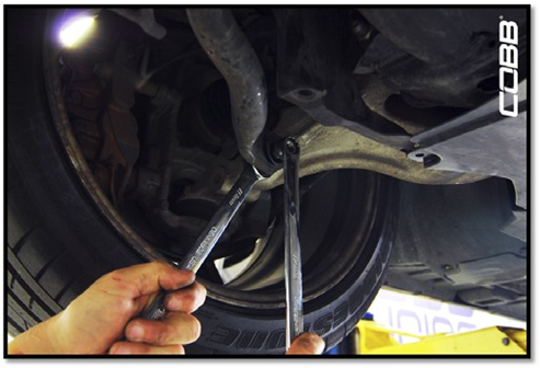
- Repeat on the opposite side.
- With both end-links free remove the four 14mm flange nuts holding the sway bar brackets in place. Make sure to support the bar before undoing the last nut and removing the sway bar from the vehicle.
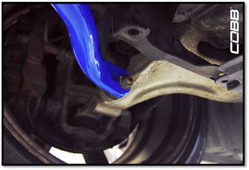
Front Sway Bar Installation
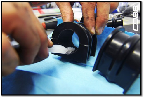
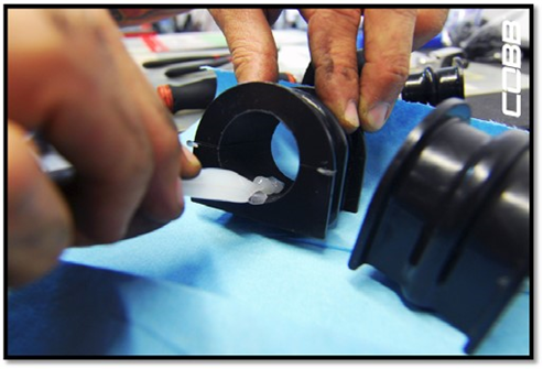
- Use the grease provided to lubricate the new replacement bushings that come with the sway bars.
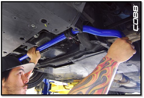
- re-install sway bar to the vehicle and secure the sway bar brackets using the existing hardware.
- Torque the 14mm flange nuts that secure the sway bar bracket to 37 ft/lbs.
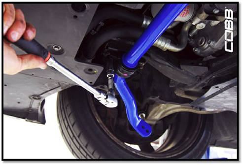
- Proceed to install the end-links on the ends of the sway bar using the existing 17mm nuts and torque them to 73 ft/lbs. (Choosing the inside mounting hole will set the sway bar to a stiffer setting, while the outer mounting hole will be looser)
5. At this point you should be able to re-install the front under-tray by reversing the steps in the removal section.
Rear Under-Tray Removal
- For CBA models (2009-2011) remove the four plastic fasteners along the rear section of the lower diffuser
DBA models (2012-2018) have a redesigned rear lower diffuser and will have five plastic fasteners instead.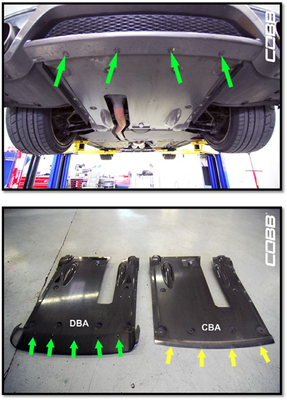
- Remove four 10mm bolts along each side of the rear lower diffuser panel (eight bolts total)
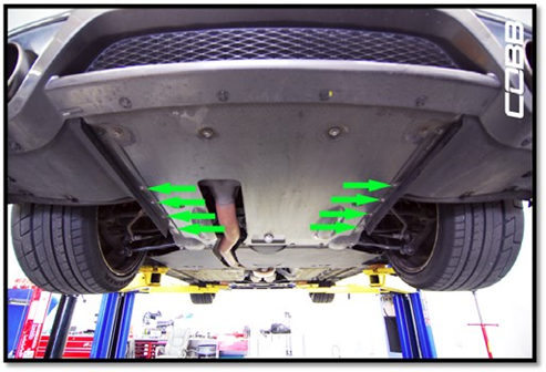
- Remove the rest of the 12mm bolts along the outside perimeter of the diffuser panel (fourteen in total) and carefully lower the center panel.
- At this point you should be able to see the sway bar and get an idea of how it mounts.
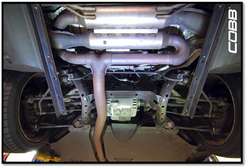
Rear Sway Bar Removal
- Remove the plastic cap to expose the 14mm flange nut from the end-link to the sway bar and remove the flange nut using a 14mm combination wrench. Use another 14mm combination wrench to hold the opposite side of the end link to prevent it from spinning under torque.
- Repeat the process on the opposite side.
- With both end-links free remove the four 14mm nuts holding the sway bar brackets in place.
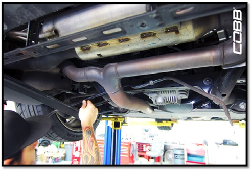
- Carefully free the sway bar from the car by fishing it out through one side of the car. (alternatively it may be easier to remove the exhaust on some vehicles if clearance is tight.
Rear COBB Sway Bar Installation
- Use the grease provided to lubricate the new replacement bushings that come with the sway bars.
- Re-install the sway bar to the vehicle and secure the brackets using the existing hardware.
- Torque the 14mm flange nuts that secure the sway bar bracket to 25 ft/lbs.
- Proceed to install the end-links to each end of the sway bar using the existing 14mm nuts and torque to 41 ft/lbs. (Choosing the inside mounting hole will set the sway bar to it's stiffest setting, while choosing the outer set will be progressively looser)
- You can now re-install the rear diffuser using the opposite order of the removal instructions.
Contact Us:
COBB Customer Support
Web Support and Tech Articles: COBB Tuning Customer Support Center
Email: support@cobbtuning.com
Phone support available 9am to 6pm Monday-Thursday. 9am to 4pm Friday (CST)
866.922.3059
return to www.cobbtuning.com
Copyright 2025 © COBB Tuning Products LLC. All Rights Reserved. | www.cobbtuning.com