Subaru Accesstuner FA24DIT Ascent Tuning Supplement
- Bill Gregg
- Brandyn Mowat
- Mike McGinnis
- Will Trang
Introduction
With the exception of boost control, the Ascent ECU generally shares the same logic as the DIT WRX ECU (FA20DIT motor) with only minor differences. Boost control code is entirely new on the Ascent due to the introduction of a fully electronic wastegate valve and air bypass valve on its FA24DIT motor. Subaru advertises the Ascent CVT transmission as a "high torque" unit, but some owners of stock vehicles are reporting transmission failures on the stock tune. Tuning your vehicle voids your powertrain warranty. Tuning products are to be used at your own risk, so consider carefully before proceeding.
Boost Control
The general behavior of the new boost control logic for the FA24DIT motor is similar to the FA20DIT logic. Instead of determining a commanded wastegate duty, the new logic determines a commanded wastegate shaft position. It uses a boost targets table with baro and IAT comps, proportional/integral (PI) loop based on boost error ("turbo dynamics"), and an initial wastegate position table also with baro and IAT comps. Additionally, there are new DTCs pertaining to boost control and new tables for controlling the air bypass valve state.
Boost Targets
%202019%20USDM%20Ascent%20CV.jpg?version=1&modificationDate=1550611572114&cacheVersion=1&api=v2)
This is very similar to the FA20DIT logic. The final boost target is determined via a 3D boost targets table (requested torque vs. RPM) with compensation tables for baro and IAT applied. The main difference here is that the requested torque used for the boost targets table is based on the traditional requested torque value, but also further manipulated by two adders related to A/C and alternator load (see the "Requested Torque (Boost Targets)" section below).
Wastegate Position
%202019%20USDM%20Ascent%20CV.jpg?version=1&modificationDate=1550673531160&cacheVersion=1&api=v2)
The starting commanded wastegate position is determined by the Wastegate Initial Position table (final boost target vs RPM) with compensations for baro, IAT, and initial position (this one is fairly redundant and the factory calibration is set to no comp). Wastegate position is represented in units of length (millimeters). The wastegate is more progressively open with higher values. This initial position is corrected by the turbo dynamics corrections based on boost error (described in next section). This commanded wastegate position ranges from 0 mm (full closed) to 15 mm (max. open) and is reflected in the Wastegate Position Commanded monitor.
The final commanded wastegate position (represented in the Wastegate Position Commanded Final monitor) is typically different than the initial commanded position described above due to a learning adjustment and ramping behavior:
- When the commanded wastegate position is near 0 mm (i.e. request fully closed), the ECU enters a learning mode where the final commanded position is set to a fixed (low) position with a previous learning adjustment applied. The evaluation requires 1 second of time (where commanded position remains near 0 mm) after which the current (actual) wastegate position is sampled once and a learning adjustment is derived from this actual position vs. the theoretical fully closed position (0 mm). This difference becomes the new learning adjustment (shown in the Wastegate Position Learned Correction monitor) which is always added to the commanded position (with the total reflected in the Wastegate Position Commanded Final monitor).
- If the commanded position is within 2.25 mm of the fully closed learned position, the ECU will slow the adoption of the commanded value by ramping down to it or, at times, hold the commanded value for a very brief period. This entire process occurs, typically, in less than half a second (at the start of a WOT pull for example).
The following monitors can be used to track the wastegate position elements.

Turbo Dynamics
%202019%20USDM%20Ascent%20CV.jpg?version=1&modificationDate=1550674889008&cacheVersion=1&api=v2)
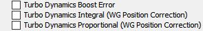
A PI loop governs the wastegate position correction based on boost error. The integral and proportional tables are 3D tables (boost error vs. RPM). This is fairly similar to the FA20DIT logic overall. The following monitors can be used to track boost error, integral, and proportional corrections:
Boost Control Activation
%202019%20USDM%20Ascent%20CV.jpg?version=1&modificationDate=1550675519285&cacheVersion=1&api=v2)
Boost control activation is determined by a minimum requested torque threshold with compensations for baro and IAT.
Tuning boost control:
While the mechanical system and logic have changed, tuning boost control remains largely the same as other Subarus. Tuning the Wastegate Initial Position table is performed much like tuning a wastegate duty cycle table, except higher values will result in more wastegate flow (less boost), lower values result in less wastegate flow (more boost). The table also uses the final boost target (relative to sea level) rather than requested torque or throttle position, which we feel makes it even easier to work with. In testing, values tuned at low altitude still performed well at high altitude, but this may vary with mechanical configuration. Keep in mind the position required to achieve a given target boost level will also vary with changes in mechanical configuration. We suggest tuning the whole table to achieve consistent mild negative integral values to avoid significant spiking, and achieve a smooth boost curve. Comparing an OTS performance map to stock will illustrate additional changes which made boost control more smooth and predictable compared to stock, but feel free to explore and find a better way.
Air Bypass Valve
On a mechanically stock vehicle, the stock values seem to work well and have not been adjusted in OTS Stage1 maps.
CLOSED TO OPEN STATE
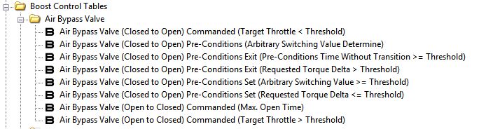
To change the bypass valve from a closed to open commanded state, the following needs to occur:
- "Pre-Conditions" Set - the following two table thresholds have to be met in order for the pre-conditions state to be "set" (i.e. active). Once this is set (as long as it does not exit the pre-conditions state), these thresholds no longer have to met.
- Air Bypass Valve (Closed to Open) Pre-Conditions Set (Arbitrary Switching Value >= Threshold)
- Air Bypass Valve (Closed to Open) Pre-Conditions Set (Requested Torque Delta <= Threshold)
- Target throttle has to drop below this table's threshold when the pre-conditions state is still set. When this occurs, the bypass valve commanded state will move from closed to open.
- Air Bypass Valve (Closed to Open) Commanded (Target Throttle < Threshold)
- Air Bypass Valve (Closed to Open) Commanded (Target Throttle < Threshold)
- The pre-conditions state can become inactive (exit the "set" state) if any of the following thresholds are met. When this occurs, conditions to set the pre-conditions state will have to occur again for the possibility of a closed to open commanded state. Effectively, the maximum allowed delay between when the pre-conditions state is set and the target throttle threshold can be met is governed by these tables.
- Air Bypass Valve (Closed to Open) Pre-Conditions Exit (Pre-Conditions Time Without Transition >= Threshold)
- Air Bypass Valve (Closed to Open) Pre-Conditions Exit (Requested Torque Delta > Threshold)
OPEN TO CLOSED STATE
The bypass valve will move from an open to a closed commanded state when either the bypass valve commanded state is open beyond the max. allowed time or the target throttle exceeds a specific threshold:
- Air Bypass Valve (Open to Closed) Commanded (Max. Open Time)
- Air Bypass Valve (Open to Closed) Commanded (Target Throttle > Threshold)
The commanded state can be tracked via the following monitor:

Boost Limits - P226B (Fuel Cut and Throttle Cut)
%202019%20USDM%20Ascent%20CV.jpg?version=1&modificationDate=1550692373029&cacheVersion=1&api=v2)
This logic is the same as the FA20DIT and governs the activation of the DTC, fuel cut and throttle cut when boost exceeds the boost limit (with corresponding adder). The only difference is that the 1st gear, baro, and IAT compensations to the boost limit are distinct to this boost limiter and not used for the boost target (as opposed to the FA20DIT where they are shared). The P226B replaces the P0244 code in the 19+ WRX and STi as well as here on the Ascent, however, the Ascent also makes use of the P0244 code (which WRX/STi does not) for another purpose (as described below).
Boost Limits - P0244 (Wastegate Position Error)
%202019%20USDM%20Ascent%20CV.jpg?version=1&modificationDate=1550692454832&cacheVersion=1&api=v2)
The Ascent ECU re-purposes the P0244 code as a means to sanity check operation of the electronic wastegate valve. If the wastegate position error (commanded - actual) is outside a specific range (-6.4mm to 6.4mm) for a certain period of time, P0244 will be thrown.
Boost Limits - P0234 (Boost Error Overboost)
%202019%20USDM%20Ascent%20CV.jpg?version=1&modificationDate=1550692530911&cacheVersion=1&api=v2)
When boost control is active, if boost error is less than the overboost limit value continuously for the specified delay period, the P0234 code will be thrown.
Boost Limits - P0299 (Boost Error Underboost)
%202019%20USDM%20Ascent%20CV.jpg?version=1&modificationDate=1550692561303&cacheVersion=1&api=v2)
When boost control is active and a minimum target boost threshold is met (2d vs. RPM), if boost error is greater than the underboost limit value continuously for the specified delay period, the P0299 code will be thrown.
Requested Torque (Boost Targets)
Requested torque logic generally works about the same as prior DIT but does have some unique properties for Ascent:
- Unlike the DIT CVT WRX/FXT, the Ascent does NOT have SI-DRIVE so there are no SI-DRIVE specific tables. The Ascent does have X-MODE however, so there are X-MODE requested torque tables defined.
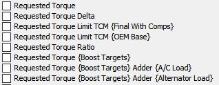
- The requested torque input to the Boost Targets table (Requested Torque (Boost Targets) monitor) has some additional compensations to the normal requested torque value (Requested Torque monitor). These compensations are adders to the normal requested torque value based on A/C compressor and alternator load and can be monitored via the Requested Torque (Boost Targets) Adder (A/C Load) and Requested Torque (Boost Targets) Adder (Alternator Load) monitors. These adders, generally speaking, typically range from 0 to about 30 N-m (each) which will increase the requested torque input to the Boost Targets table (potentially increasing boost target).
Other Logic Differences
MAF Calibration (Frequency)
MAF sensor calibration is based on MAF sensor frequency rather than voltage. The MAF calibration table is scaled from 1.17 kHz to 10 kHz and this axis can be tuned (i.e. unlike the FA20DIT which is a fixed read-only voltage axis). The table is tuned in the same manner as a voltage based MAF calibration, with larger mass airflow values resulting in increased calculated load and fuel delivery.
%202019%20USDM%20Ascent%20CV.jpg?version=1&modificationDate=1550680675201&cacheVersion=1&api=v2)
Ignition Timing Comp (IAT)
%202019%20USDM%20Ascent%20CV.jpg?version=1&modificationDate=1550679853663&cacheVersion=1&api=v2)
The IAT ignition timing comp logic has changed with the Ascent ECU. The MAF-based IAT compensation is determined by adding (Intake Temp) 1 (with activation applied) to (Intake Temp) 2 (with activation also applied). This sum is then limited to a maximum determined by the Ignition Timing Compensation (Intake Temp) Max. Limit (Manifold Temp Calc)... tables as follows: ((Base Temp) - (current Intake Temperature Manifold)) * (Ignition Timing Compensation (Intake Temp) Max. Limit (Manifold Temp Calc) Compensation table. This is then limited to a maximum of 0 degrees (so the limit cannot be greater than 0).
The #1 and #2 tables are zero'd out in the factory tune so the manifold temp tables entirely govern the final compensation in the factory calibration. This will be a negative value when manifold temp exceeds the Base Temp table (load vs. RPM) value. The result is corrected by the A/B Compensation table (load vs. RPM). The greater the manifold temp exceeds the Base Temp value, the more negative the compensation will be (all else equal).
An example for this calculation is as follows:
manifold temperature = 90 degrees F
Ignition Timing Compensation (Intake Temp) Max. Limit (Manifold Temp Calc) Base Temp table = 60 degrees F
Ignition Timing Compensation (Intake Temp) Max. Limit (Manifold Temp Calc) Compensation table = 0.25
The maximum limit will be (60 - 90) * 0.25 = -7.5 deg. If the Ignition Timing Compensation (Intake Temp) table with Activation table applied was 0 degrees, then the final timing compensation for intake temp would be -7.5 degrees. Increasing the Base Temp table will require a higher manifold temperature before a negative max limit is applied and increase the max limit (i.e. less negative) all else equal. Decreasing this table will have the opposite effect. Note: Because the final max limit cannot be greater than zero, this means that the final ignition timing compensation for intake temperature cannot be greater than 0. Also, because the ECU uses lower precision math for this function, the final actual ignition compensation may be lower than your calculation by up to about 1 degree.
Related content
Copyright 2025 © COBB Tuning Products LLC. All Rights Reserved. | www.cobbtuning.com