3C1700 - Nissan CAN Flex Fuel Kit
- Brandyn Mowat

3C1600 – Nissan CAN Flex Fuel Kit
Nissan GTR 2008 - 2018
Congratulations on your purchase of the COBB Tuning Nissan CAN Flex FUel Kit! The following instructions will assist you through the installation process. Please read them BEFORE beginning the install to familiarize yourself with the steps and tools needed. If you feel you cannot properly perform this installation, we HIGHLY recommend you take the vehicle to a qualified and experienced automotive technician.
IMPORTANT! Installing this kit will require custom tuning or utilizing an appropriate Stage Power Package map if you have a matching mechanical configuration. Please consult with COBB or an authorized ProTuner in your area if you have any questions!
Table of Contents
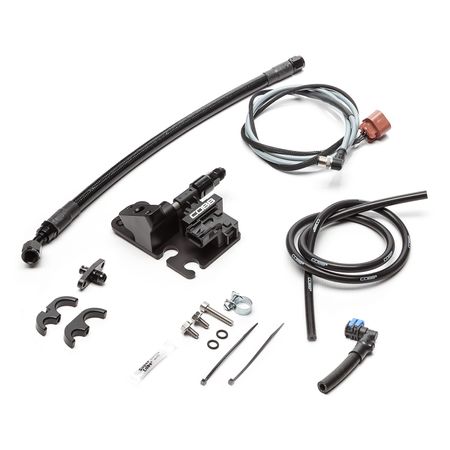
Parts List
- Flex Fuel Sensor Mounting Plate
- Flex Fuel Sensor
- -6AN male to 3/8" SAE Quick Disconnect fitting
- 52F Fuel Injection Clamp
- (2) 6x12mm flanged bolt
- Gateway Input Harness
- FPR to Return Fuel Line
- Fuel Rail to Sensor Fuel Line
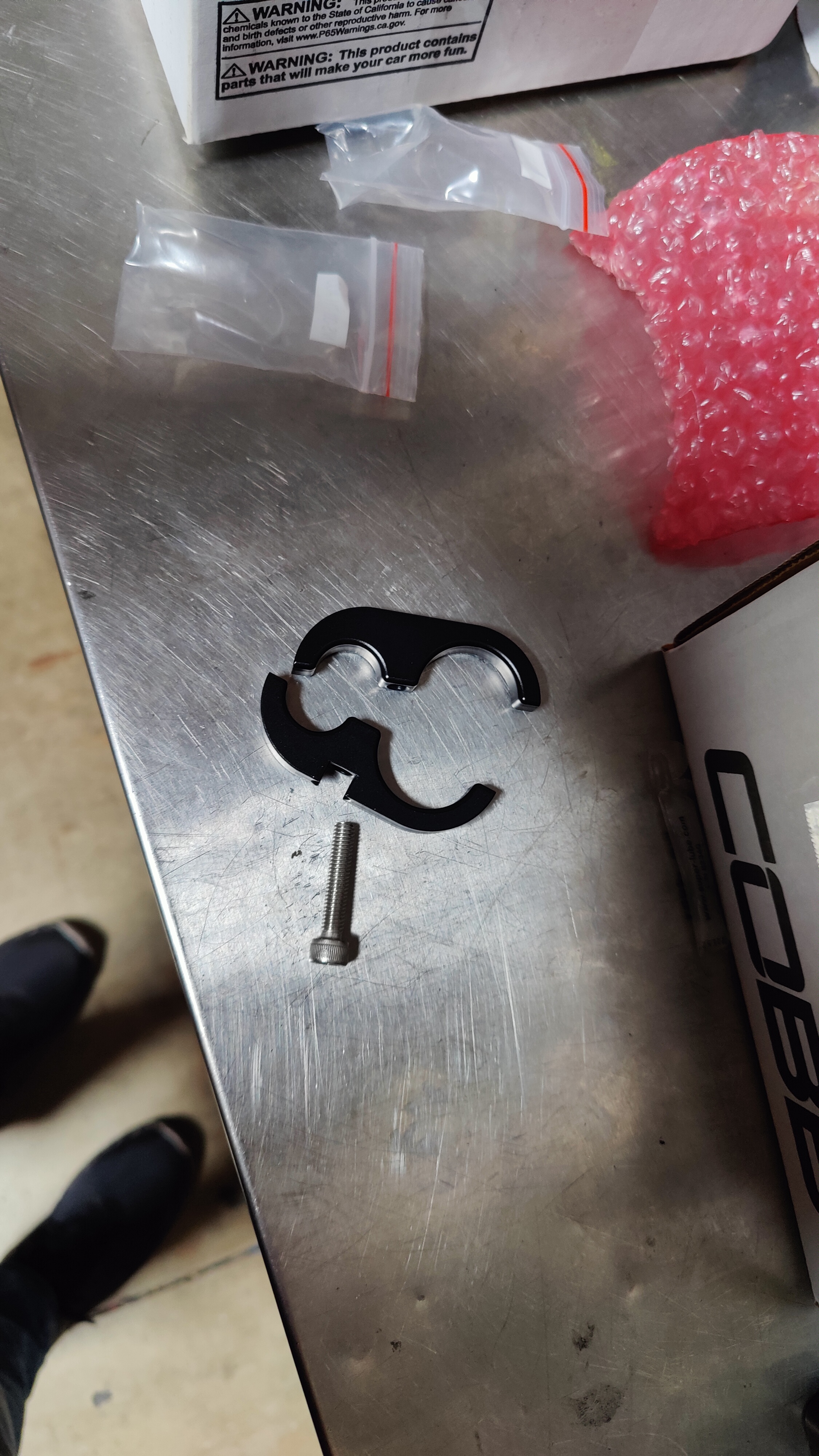
- Coolant Hose Separator
Tools Needed
- Phillips head screwdriver
- Flathead screwdriver
- 3/8" ratchet
- 3/8" 10mm socket
- 3/8" 12mm socket
- 3/8" 12" extension
- 3/8" 6" extension
- 3/8" 5mm Hex Key or Hex Socket
- Trim removal tool
- Needlenose pliers
- Rag or cloth to absorb fuel
Stock Component Removal
- With your car parked in a flat, level area go ahead and remove the fuel cap. This process should release most of the pressure built up into the fuel system.
- Popping open the battery cover, Using a 10mm wrench, unhook the negative terminal of the battery.
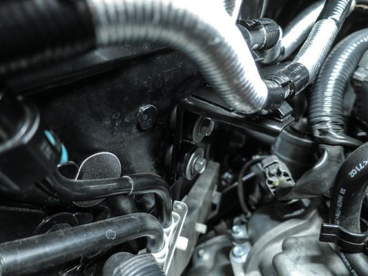
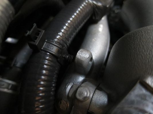
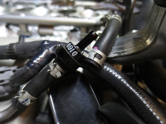
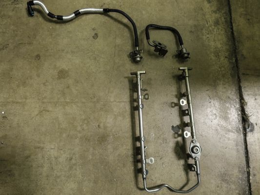
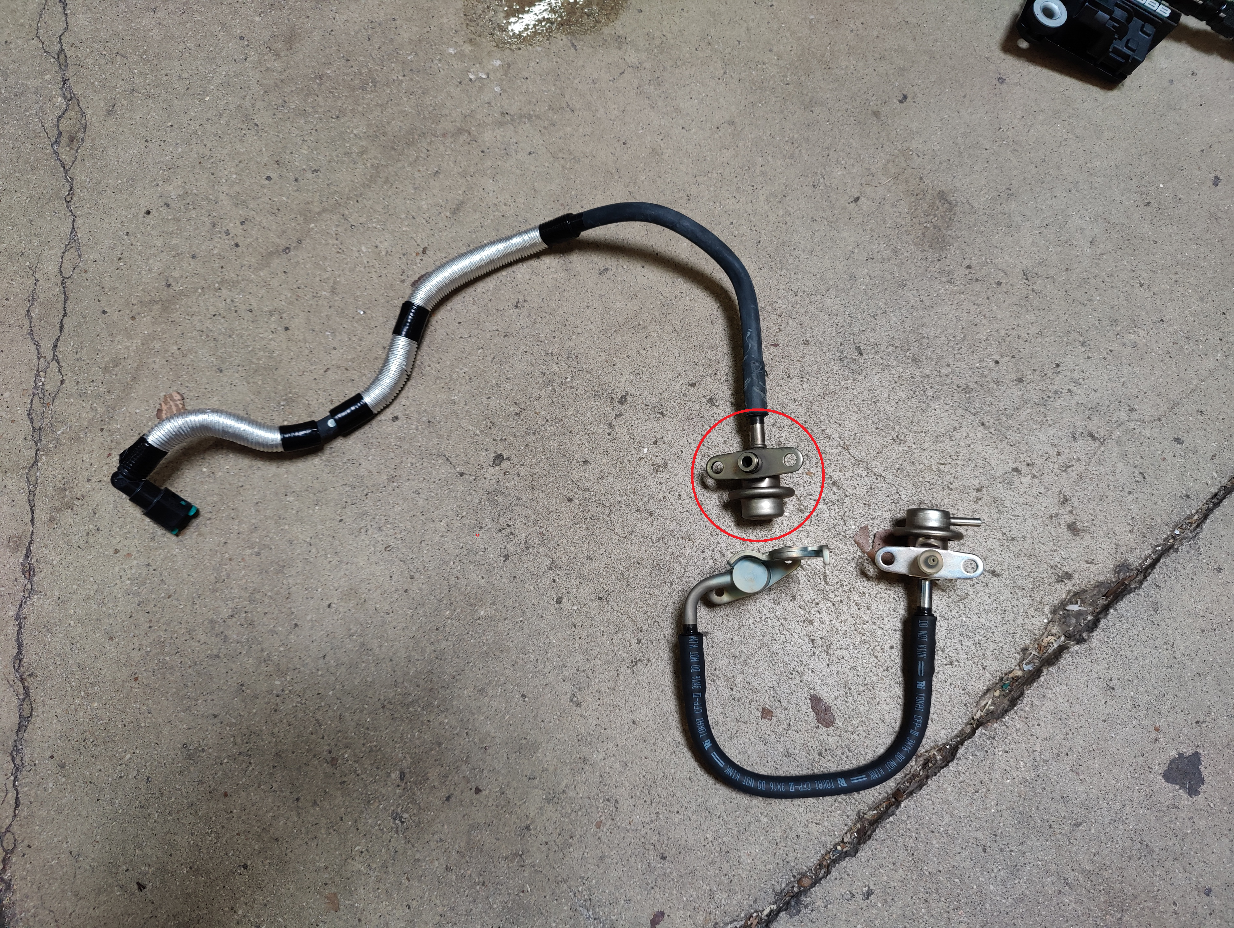
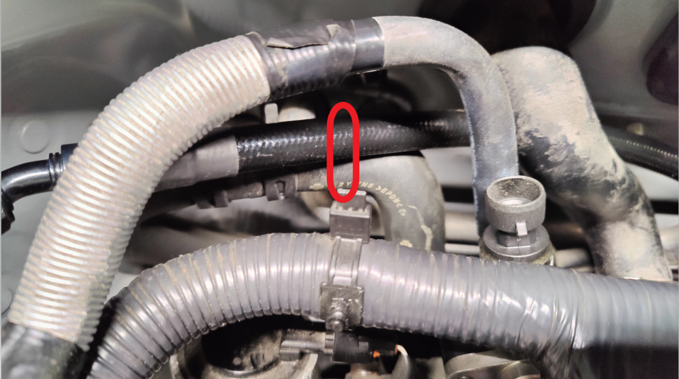
- On the passenger's side (USDM) locate these fuel lines. Unclip the lines from the retaining bracket.
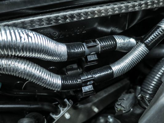
- Unbolt the bracket using a 10mm socket.
- With the bracket removed, pop out the center metal insert and the rubber bushing. Then insert them into the COBB Flex Fuel Sensor Assembly.
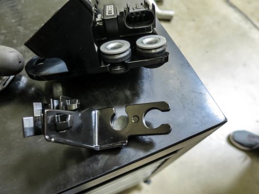
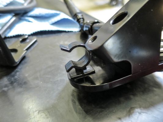
- Now squeeze the plastic clips on the hose retainer and install it onto the flex fuel unit.
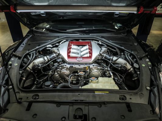
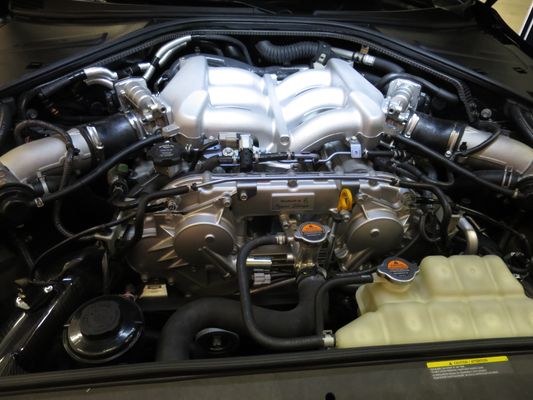
- With a 5mm Allen wrench or socket, remove the engine cover. Make sure not to lose the metal spacers out of the bottom as digging things out of the engine bay can be a huge pain!
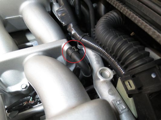
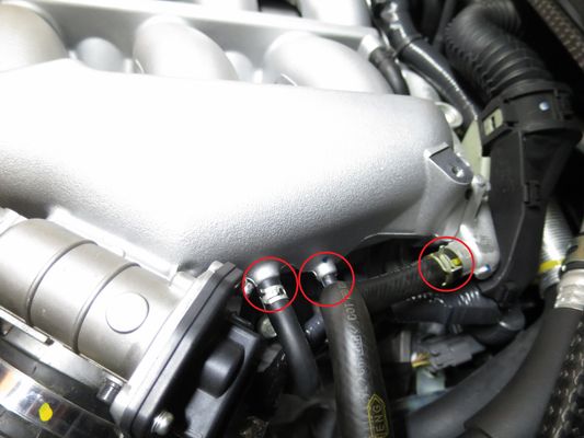
- Using pliers to loosen the hose clamps, remove all of the vacuum lines on the intake manifold, there should be 3 on the driver's side (USDM) and one on the passenger's side along with one in the back.
- Using a Philips screwdriver (or a 7mm / 8mm socket depending on the clamp) loosen the throttle body coupler
Note: On 2008-09 MY vehicles there will be a coolant line attached to each throttle body, for this reason in many instances it's easier to unbolt the throttle body from the manifold itself, in which case you can simply skip step 5 and 6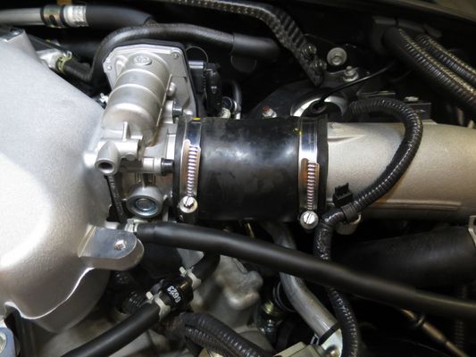
- Using a small pick or your fingers, unhook the wiring for the throttle body by depressing the connection and carefully pulling out on the connector.
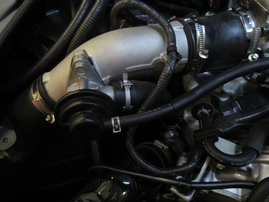
- Using pliers squeeze the clamp together for the recirculation pipe, and pull the tube off of the bypass-valve, once done you can wiggle the whole tube free and roll it to the side and out of the way.
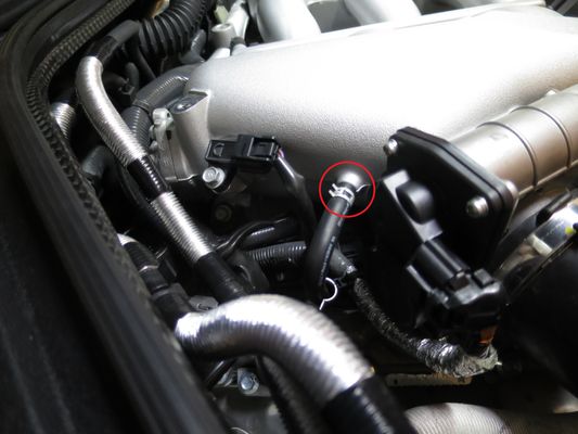
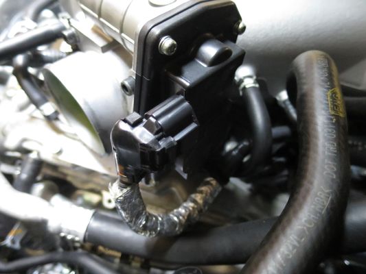
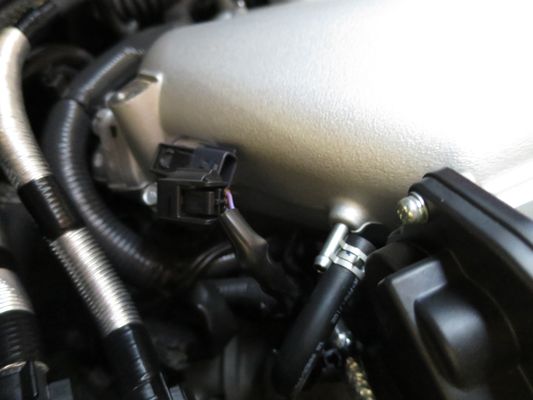
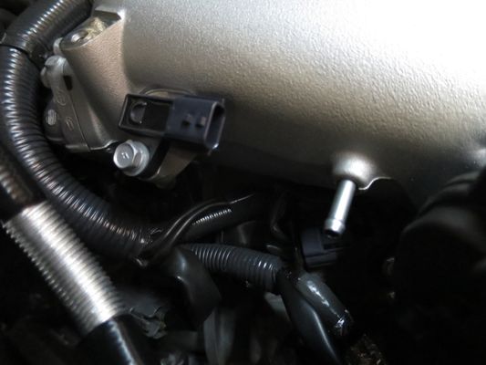
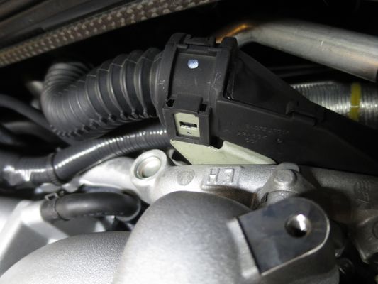
- With the charge pipes out of the way unhook the MAP sensor on the passenger's side of the manifold.
- Using a trim pry tool, carefully pop the wire ties out of their mounts on the back of the manifold.
- Depressing the clip in the center of the hole, pull up on the harness so that it is no longer attached to the mount.
- Moving over to the front of the intake manifold, unbolt the two 10mm bolts holding the cross-over pipe in place and gently pull it out of the way. Pulling the check valve out of one end of the line can make it easier to get fully out of the way.
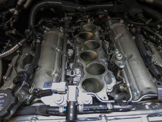
Using a 10mm socket, remove the 8 bolts holding the upper half of the intake manifold on. Once done, carefully remove making sure not to pull on any harnesses or lines.
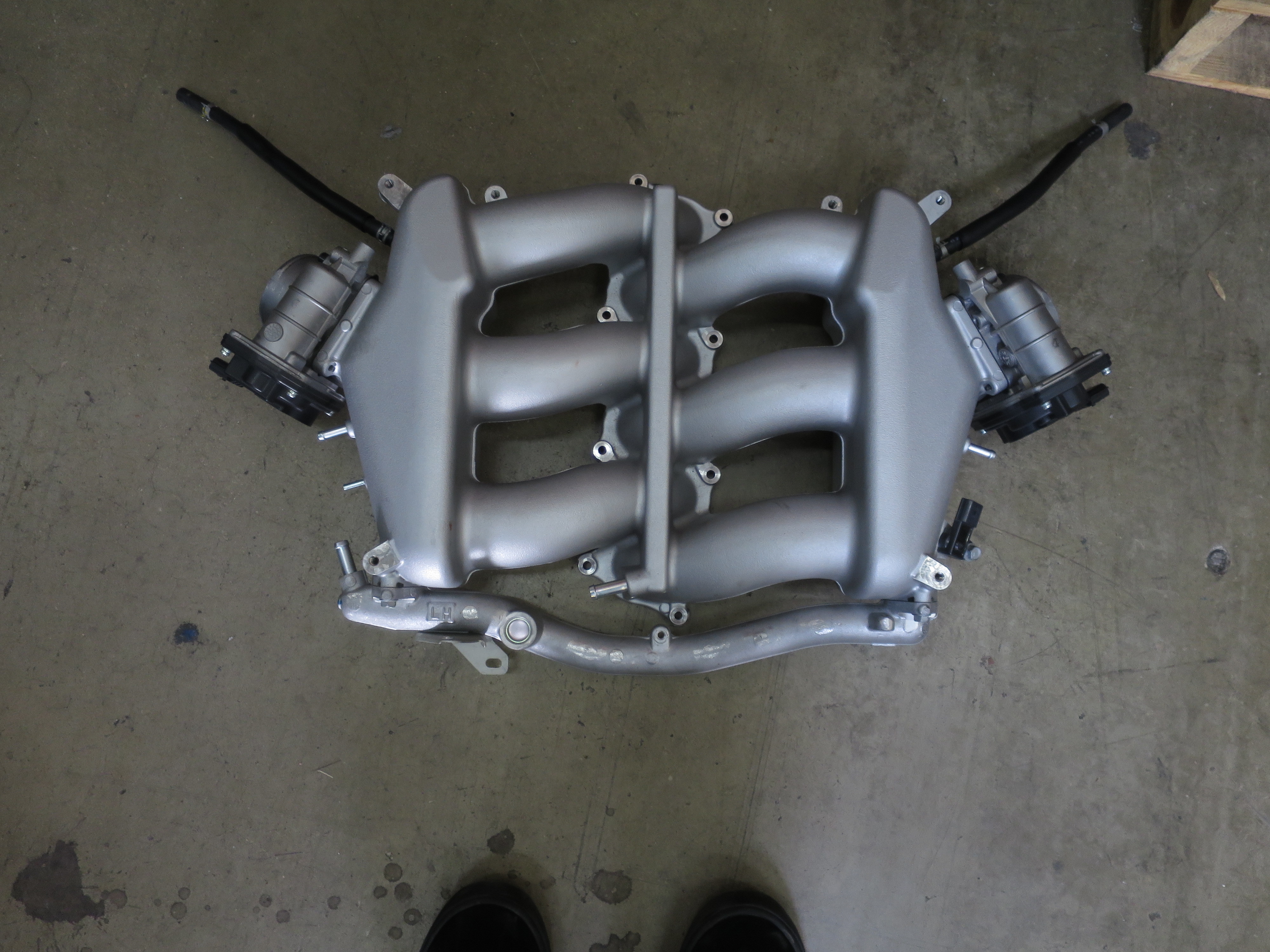

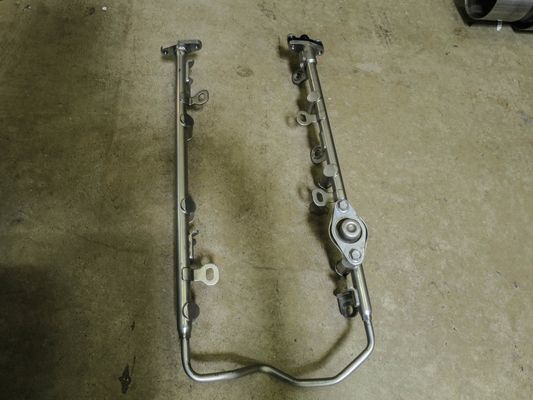
The following steps can be done with the fuel rail on the car, the pictures are taken off of the car in order to get a better look at everything.
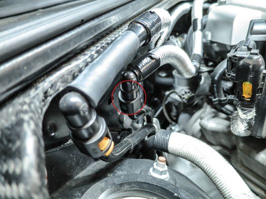
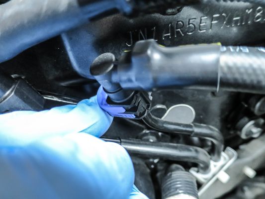
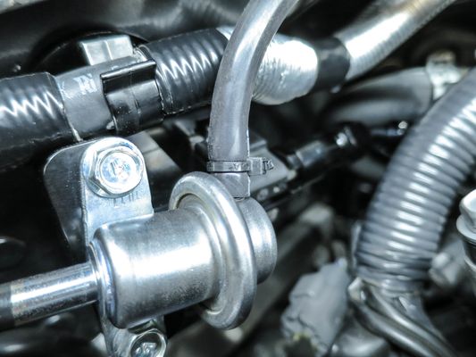
- Disconnect the return line at the firewall connection. You can do this by squeezing the two tabs on the end in and pulling out. It's usually a good idea to have a rag to catch any residual fuel in the line.
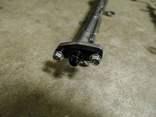
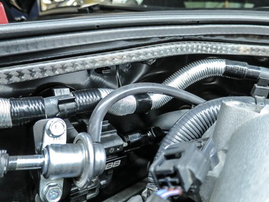
- Go ahead and remove these 3 12mm bolts and pull out the return line and fuel pressure regulator as a unit. (It's not necessary to remove the entire fuel rail)
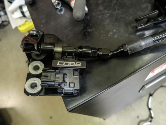
COBB Flex Fuel Assembly Installation
- Using the fuel rail to AN adapter lubricate the o-rings using superlube or another good quality silicone lubricant then install onto the fuel rail.
- Now on the fuel system side, attach the straight fitting of the AN line to the adapter fitting on the ethanol content sensor and tighten it using a -6 AN wrench
- On the factory fuel pressure regulator, cut off the stock fuel line as well as the nylon piece underneath using a razor blade. Be careful not to score the fitting underneath.
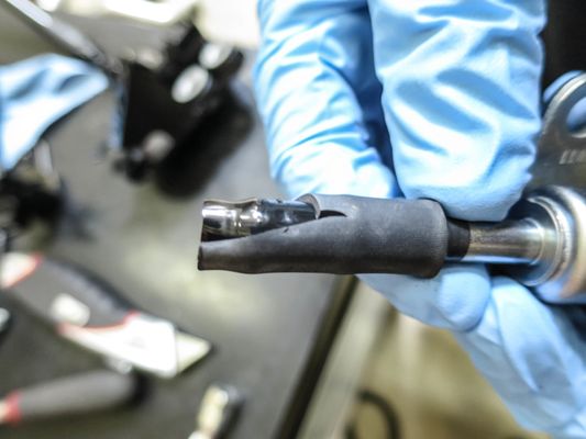
- Once done lube up the o-ring on the fuel pressure regulator and install it into the COBB Flex Fuel Sensor Assembly with the fuel line pointing the opposite direction of the AN line. Before doing so replace the o-ring as needed with the one provided.
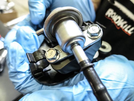
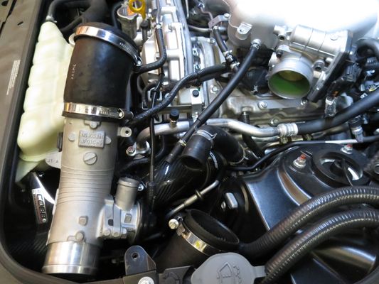
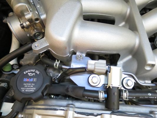
- Tuck the AN line into the other lines behind where the intake manifold will go and attach it to the 45 degreeAN Fitting on the fuel rail loosely, then bolt the COBB Flex Fuel Sensor Assembly down to the firewall using the stock 10mm bolts
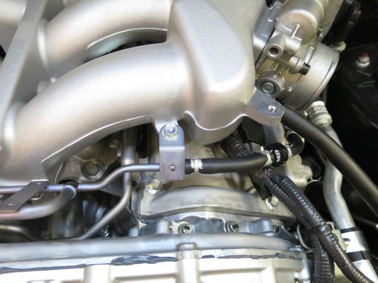
- With that tightened down, go back and tighten the AN fitting to the rail using a -6 AN wrench.
- Tighten the AN fitting on the unit itself using the same wrench.
- Install the line separator using your allen wrench to hold the AN line away from the coolant line's metal hose clamps (you can also rotate those out of the way for extra safety.
- Install the fuel line to the flex fuel assembly and put a hose clamp over the line before sliding it onto the fuel pressure regulator.

- After applying more lube to the tip of the factory hardline, install the provided short fuel line onto the factory return hardline.
- Clip the blue retainer shut
- Tighten down the hose clamp making sure that it is tight but not crushing the rubber.
- Re-Install the stock intake manifold and electronics as well as hoses in the reverse order of removal.
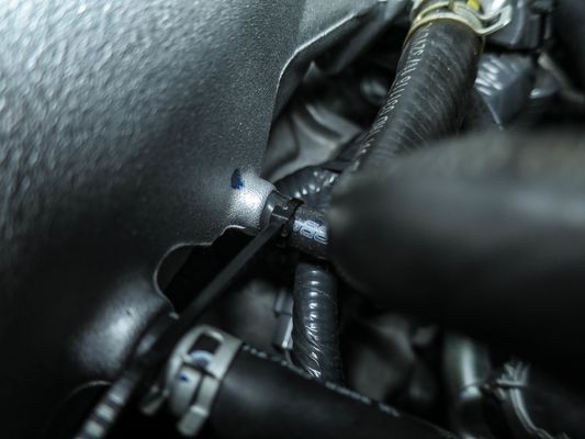
- Install a piece of the vacuum line on to the factory regulator then route it to the original port on the manifold
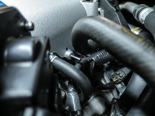
- Zip tie both ends of the vacuum line to prevent air leaks.
- Let the car sit to allow any fuel to disburse as needed to prevent a fire. Tighten as needed.
- Turn the ignition on but don't start the car and check for leaks. With a friend in the driver's seat or watching the fuel system, start the car up and check for leaks. Tighten as needed.
- Flash an appropriate map to your car and go out and enjoy!
Links
Map Notes for GT-R
Helps to figure out which map you should be on given the parts installed to your car
COBB Customer Support Web Support and Tech Articles: COBB Tuning Customer Support Center Email: support@cobbtuning.com Phone support available 9am to 6pm Monday-Thursday. 9am to 4pm Friday (CST) 866.922.3059 return to www.cobbtuning.comContact Us:
Related content
Copyright 2025 © COBB Tuning Products LLC. All Rights Reserved. | www.cobbtuning.com