Mitsubishi Tuning Guide
- Will Trang
- Brandyn Mowat
- Former user (Deleted)
- Former user (Deleted)

![]()
Mitsubishi Evolution X and Lancer Ralliart
Version 4.00
Date Revised: 9/16/2016
This tuning guide is broken into the basic components of tuning a Mitsubishi Evolution X or Lancer Ralliart and the tables associated with each of these components. The guide outlines basic tuning strategies and defines tables for each major tuning category, such as boost control, fueling, and ignition timing.
Tuning Guide
Step 1 – What is the mechanical configuration of the vehicle?
The first step in tuning an Evolution X or Lancer Ralliart is choosing a COBB Tuning Off-The-Shelf (OTS) calibration that most closely matches the mechanical components and modifications of the vehicle to be tuned.
The Stage1 calibrations are designed for vehicles with little to no aftermarket modifications (cat-back exhaust systems are OK). The Stage2 calibrations are designed for vehicles with an upgraded turbo-back exhaust system. This major difference in configuration impacts the pumping efficiency of the motor and critically impacts all major aspects of tuning (boost, fuel, and ignition).
Step 2 – What fuel is the vehicle using?
Note that COBB Tuning offers calibrations for three different fuels: 93 octane (98 RON), 91 octane (95 RON), and ACN91 (91 octane from Arizona, California, or Nevada). Higher octane ratings indicate higher quality fuel that burns more slowly and can support higher cylinder pressure. This difference in fuel will determine how the car is tuned. Take a moment to compare and contrast timing, boost, and ignition tables from each type of calibration. Higher octane fuels support more ignition timing, higher boost levels, and leaner air-to-fuel mixtures compared to lower octane. Using a map designed for high octane with low octane fuels can result in damage to the motor.
Step 3 – What type of air intake is on the vehicle?
The Evolution X and Lancer Ralliart utilize a mass air flow (MAF) sensor located downstream to the air filter and before the turbo to measure the amount (mass) of air entering the motor. This air flow measurement is CRITICAL for boost control, ignition timing, and fuel. This sensor reports the amount of air entering the motor, which is used to determine load. Many tables inside the ECU use Load and RPM as their axis. Therefore, it is the MAF sensor reading, through calculated load, that determines the table values used to control the motor.
MAF sensor readings are entirely dependent upon the type and design of the intake system. Aftermarket intakes rarely promote laminar airflow around the MAF sensor equivalent to the stock intake system. As a result, the stock MAF sensor calibration is not appropriate for most aftermarket intakes. If an aftermarket intake is used, the tuner will have to put forth considerable effort to ensure that the MAF sensor is appropriately scaled to the airflow characteristics of the new intake system. We highly suggest that you complete the initial tuning with the stock intake system in order to establish a proper tune using a known MAF sensor calibration. Once the tune is optimized for the stock intake system, the aftermarket intake can be installed to complete the MAF calibration with the otherwise complete tune.
COBB Tuning offers maps that support the stock intake as well as the COBB SF intake for the Evolution X GSR and MR. If a calibration is not available for your intake, you will need to complete a deliberate process to create MAF sensor calibration.
Step 4 – Calibration refinement on a chassis dynamometer.
A: Perform initial testing at low boost.
After selecting the most appropriate initial calibration, prepare to test and refine the calibration on a chassis dynamometer. When creating a custom tune, it is best to begin testing under low load conditions by lowering values in the Boost Target Engine Load tables, decreasing boost targets. This lowers the requested load (boost). Lowering the target load alone will not produce stable and low boost levels, so it is also advisable to reduce the wastegate duty cycles in the Passive and Reactive Solenoid WGDC tables by a similar percentage. Testing done at lower boost will allow you to assess the calibration without putting the motor under potentially dangerous conditions. Start the tuning process by loading this "low boost" starting point calibration onto the vehicle.
B: Connect the Accesstuner software to the Accessport equipped Evolution X.
Open the selected starting calibration in the Accesstuner software then configure the Accesstuner software to connect to your vehicle. Attach the OBDII connector to the vehicle and, to your Accessport (if applicable), then connect the associated USB cable to your computer. Press "Ctrl+F" to configure the program. Select the directory in which to store your data logs under the "Logging" tab. You can also integrate a wide-band O2 (WBO2) sensor signal into the data log by selecting the specific oxygen sensor you wish to use and indicating its associated COM port with the tabs to the right of "Communications."
C: Log critical engine parameters while testing.
Accesstuner software allows the user to sample and record critical engine parameters including sensor information and commanded engine function. Open Accesstuner and load the calibration currently flashed to the vehicle. Attach the OBDII cable to the vehicle and the computer. Press "Ctrl+F" to configure the logged parameters in the "Log List" tab, and those displayed in the Accesstuner "Dashboard" through the "Gauge List" tab. The Dashboard, a screen that reports active engine and sensor parameters, can be accessed by pressing "Ctrl+B." It is critical to actively monitor the condition of the motor during tuning and this screen is the single best way to do so. These data monitors allow the tuner to determine if a calibration is performing correctly. Accurate and deliberate assessment of logged parameters is the only way to avoid conditions that may damage the motor.
If more than 12 parameters are selected at any one time, the rate of data collection will be lower than optimal. With 12 or fewer parameters the logging rate should be 7 to 8 Hz.
Below is a list of parameters that can be logged with the Evolution X GSR, MR, or Lancer Ralliart. The selected parameters are those that are critical to record under most conditions, while other parameters may be selected or removed based upon the objectives of any specific tuning process. Please note that some parameters may not be available due to the lack of hardware on your vehicle (SST).
D: Tuning for appropriate Air to Fuel Ratios (Lambda)
The ideal air to fuel ratio (AFR) depends upon fuel quality, engine design, fueling model (port injection, DISI, diesel, etc.), heat exchanging abilities, and other variables. Higher octane fuels are more stable at higher cylinder pressures, and are more resistant to preignition. Leaner AFRs can produce higher power, but also create more heat that may lead to unsafe preignition. Lower octane fuels, such as 91(95 RON) and ACN91 (Arizona, California and Nevada 91 octane), are less resistant to detonation and require a richer (fewer parts air per parts fuel) AFR for safer operation. Richer AFRs produces less heat, protect against detonation due to a cooling effect of the excess fuel and usually produce less power. We have found that the Evolution X motor can run high 11 to low 12 Air to Fuel ratios with high quality fuels. Lower quality fuels require mid to low 11 air to fuel ratios.
Air to fuel ratios for these vehicles are directly impacted by several tables. The High Octane Fuel Map is the main table dictating open loop fuel mixtures. These tables are referenced by Load and RPM. By logging Load and RPM, you will be able to identify the portions of the tables that need to be edited to produce desired fueling.
There are two primary fuel tables: Low Octane Fuel Map and High Octane Fuel Map. The High Octane Fuel Map is used when the learned knock is 100. If the learned knock begins to fall below 100, a mixture of Low and High octane tables determines final fueling. For example, if the learned knock correction is 90 the final fueling is and average of 9 parts High Octane Fuel Map + 1 part Low Octane Fuel Map.
A fuel mixture that is too lean will contribute to uncontrolled combustion, excessive heat, detonation and possible engine damage. The objective is to run the car at the richest air to fuel mixture possible that does not sacrifice power. Ultimately, the best air to fuel can only be determined in concert with changes to ignition timing. For example, some cases a comparatively rich air to fuel mixture can be run with more dignition timing than a leaner mixture. This combination may produce higher power than a lean mixture with less ignition timing. Generally speaking, the air to fuel and ignition timing combination that produces the best power while minimizing heat is the desired calibration. Of course, this ideal is not limited to ignition timing and fuel, but is also a balance of variable cam timing and boost pressure.
E: Tuning Ignition Timing
The most important tables for ignition timing are the Low Octane Timing Map and High Octane Timing Map. The High Octane Timing Map and Low Octane Timing Map work together to determine final ignition timing under conditions where the ECU encounters detonation. These tables are referenced by Load and RPM. The following parameters can be logged to provide a reference for the specific regions of these tables that may need to be edited to produce optimized ignition timing. Knock Sum will indicate that the ECU is removing timing to reduce engine noise and detonation. If Learned Knock decays to lower than 100%, a combination of low and high octane ignition tables are used to determine final timing. For example, a Learned Knock of 97% indicates that the final ignition timing is the sum of 97% of the High Octane Map + 3% of the Low Octane Map. Generally speaking, higher ignition timing supports higher torque and greater power. However, ignition timing should be increased with great caution. Higher timing yields are limited by fuel quality and the mechanical limitations of the motor due to higher cylinder pressure. Too much timing will produce knock sums when fuel quality is the limiting factor. When fuel quality is high, ignition timing should ONLY be added when its addition produces a substantive increase in torque and power. If increased timing does not increase torque, the extra cylinder pressure is simply producing unnecessary stress on engine components.
F: Tuning Boost, Desired Load, and Desired Torque
The stock Evolution X and Lancer Ralliart boost control system is complex. First, boost is based on target load, rather than adjusting specific boost targets. Load values are derived from the MAF signal (metered airflow) and the MAP signal (manifold pressure), and do not correlate to specific boost pressure values, but do have a direct relation in that higher load values equate to higher target boost and lower load values equate to lower target boost. There are three boost target tables. Boost Target Engine Load #1A and #1B (High Gear Range) are used for when the vehicle speed/RPM ratio is below the switch point (Boost Control RPM per MPH Xover (Gear Based)). Boost Target Engine Load #2 (Low Gear Range) is used when the ratio is above that indicated in the Boost Control RPM per MPH Xover (Gear Based) table.
The stock mechanical components may not support the boost pressures that you wish to generate with your tune. A guide to performing minor mechanical changes to allow more boost is located near the end of this document.
The desired boost can be increased by raising the values in these three tables. However, the values in these tables are limited to 159. The actual Target Load (Boost) = Boost Target Engine Load + Boost Control Load Offset. For example, if the Boost Target Engine Load is 159 and the Boost Control Load Offset is 130, the final target load (boost) is 289.
Logging Load will allow you to determine if you are reaching your boost target. If you cannot reach the target boost, you should increase WGDC in one or both of the wastegate solenoid tables (Ralliart will differ). We advise that all three wastegate maps are similar unless you wish to produce less boost at lower Speed/RPM ratios. If the target load (boost) is above the desired value you will notice that the wastegate duty cycles drop below the maximum values indicated in the Passive and Reactive wastegate tables.
It is also critical to set the boost or load limits (Boost Limit) at a value that is above your desired boost.
G: Tuning Variable Cam Timing (MIVEC)
There are 4 different variable camshaft tables that control intake and exhaust cams under either MIVEC Low Coolant Temp or MIVEC Normal Coolant Temp. Considerable effort was expended to optimize our calibrations for enhanced turbo responsiveness and mid-range torque with the stock turbo. These tables can, and should, be modified for larger turbo applications. It is highly suggested that these tables not be modified unless you can substantiate differences using a chassis dynamometer.
H: Ensuring accuracy of the load calculation is crucial
The OEM load calculation is a hybrid mix of two systems; MAF and MAP. Each of these systems requires precise calibration to work optimally. If the load calculation is inaccurate on either of these systems, it can result in poor shifting (SST), jagged ignition timing curves, sloppy boost curves, and false knock events. Our Accesstuner software allows you to disable each of these load calculation systems individually so a proper calibration can be achieved for each. It is absolutely critical that both systems are tuned properly so the hybrid strategy can perform optimally. Additionally, there are hybrid tip-in / tip-out transient thresholds that can be changed to optimize the blend of these calculations.
We recommend tuning the MAF system first for vehicles using stock turbochargers, and the MAP system first for vehicles with upgraded turbochargers. This means you will need to use the Toggles section to disable the MAF or MAP system you are not working on. To tune these systems properly, set the commanded AFR (Lambda) in your High Octane Fuel map to what you would like to see from the Wideband Air/Fuel sensor. Adjust the MAF Sensor Scaling table until the values result in an AFR within +/- 2% of your commanded AFR and your idle, and cruise STFT/LTFT are within +/- 3%. Once the MAF Sensor Calibration is complete, you will need to repeat the Toggle process for the MAP system. This time, you will adjust the MAP Based Load Calc (Upper/Lower/Comp Blend) tables until the values result in an AFR within +/- 2% of your commanded AFR and your idle, and cruise STFT/LTFT are within +/- 3%.
After both load calculation systems have been calibrated, the Toggles for each system should no longer be checked. With both systems fine-tuned, the car should now run consistently and shift smoother (SST vehicles). Further fine-tuning can be done to optimize the blending of these systems by making changes to the MAP/MAF Tip-in/Tip-Out Transient values. We recommend setting the Tip-In transient to 0, and the Tip-Out transient to 0 to allow optimal blending of these systems.
I: Integrating all tuning parameters for the ideal calibration
The ideal calibration for your Evolution X or Lancer Ralliart is a combination of all major tuning areas outlined above. Generally speaking, the Evolution X or Lancer Ralliart will make the most power when it runs a lean AFR with the maximum amount of ignition timing allowed by the ECU without detonating. However, the theoretical ideal of 12.5:1 air to fuel ratio and high ignition timing is not realistic for all configurations and fuels. Calibrations should be thoroughly tested on a chassis dynamometer, where the impact of tuning is easily measured, to determine if they are ideal for the vehicle, its mechanical components, and its fuel. For example, addition of ignition timing that does not result in increased torque is not ideal because it produces additional stress on engine components without a perceivable benefit. The same is true of boost and air to fuel ratio. If the vehicle can operate at a richer air to fuel ratio without losing power, it is ideal to do so. If increasing boost does not yield considerable power gain, the turbo may simply be out of its efficiency range and, in this scenario, less boost is actually more power. For a basic idea of ideal tuning parameters for your fuel type and mechanical configuration, examine the COBB OTS map notes.
J: Precautions:
Boost – The stock turbo charger can produce boost levels in excess of 30 psi, which is enough cylinder pressure to cause engine damage. Be cautious when adjusting boost control parameters, particularly when any mechanical components of the boost control system have been altered from the factory configuration.
Mechanical Boost controllers (MBC) or Electronic Boost Controllers (EBC) – Try to avoid using anything other than stock boost control or the COBB 3-port EBCS. Airflow and torque limitations can only be fully tuned and integrated into the calibration when the stock ECU is in control of boost. It is VERY difficult to get an Evolution X or Ralliart to run properly on an external boost control device.
Fuel – The stock fuel injectors are ~530cc. These vehicles can create enough airflow to run the injectors at or above their maximum capacity. This is particularly true for vehicles equipped with high flow exhaust systems and intercoolers. Be cautious about running out of injector on similarly equipped vehicles.
Torque Limiter Addendum
The Torque Limiter function allows the ECU to detect if too much or too little power is being generated by the engine. These tables must be precisely tuned under all conditions in order to avoid triggering any torque Limiter MILs. Below is a summary of the various MILs that can be triggered by improper torque Max Air Flow or Torque Limiting table settings:
What code is associated with having too low of values in the Max Air Flow Tables?
- P1235 (MAF Sensor Plausibility). This MIL code puts the car in a protective mode where idle slowly goes up and holds, then goes does back to a normal idle and holds. The ECU turns wastegate solenoid control off, as well. The ECU can be reset by the Accessport when this code is tripped. Code P1234 (TPS (Sub) Plausibility) will also trigger with part-throttle driving. This MIL code causes the vehicle to operate in a limp mode where idle rapidly goes up and down and the engine sounds as if it is misfiring. The ECU then severely limits the power output of the engine, engine RPM, and vehicle speed. It is not safe to operate the vehicle when this code is present.
What code is associated with having too high of values in the Max Air Flow Tables?
- We could not find a code associated with having too high of values in these tables. We set these table values to 1.5X the stock values and the car drove without issue.
What code is associated with having too low of values in the Torque Limiting Tables?
- P1238 (MAF Sensor Plausibility (Torque Monitor)). This code causes the vehicle to operate in a limp mode where idle rapidly goes up and down and the engine sounds as if it is misfiring. The ECU then severely limits the power output of the engine, engine RPM, and vehicle speed. It is not safe to operate the vehicle when this code is present.
What code is associated with having too high of values in the Torque Limiting Tables?
- P1238 (MAF Sensor Plausibility (Torque Monitor)). This code causes the vehicle to operate in a limp mode where idle rapidly goes up and down and the engine sounds as if it is misfiring. The ECU then severely limits the power output of the engine, engine RPM, and vehicle speed. It is not safe to operate the vehicle when this code is present.
- P1241 (Torque Limiter). This code causes the vehicle to operate in a limp mode where idle rapidly goes up and down and the engine sounds as if it is misfiring. The ECU then severely limits the power output of the engine, engine RPM, and vehicle speed. It is not safe to operate the vehicle when this code is present.
Switchable Maps
This software has been designed to allow switching between two sets of pre-tuned maps when certain conditions are met. The assortment of tunable tables can be found in the "Switchable Maps" folder in Accesstuner.
* The Passive Solenoid Base WGDC Maps (GSR/MR Only)
There are 4 methods to change the active map slot. Cruise Control Based Switching is the default method in our OTS maps.
TPS Based Switching uses the Accelerator Pedal to change the active map slot. Simply turn the ignition to the ON position (do NOT start the car) and hold the Accelerator Pedal down to the floor for 3 seconds (default). Then turn the key to the OFF position. The vehicle will now be ready to start using the next available map slot.
- Cruise Control Based Switching uses the ON/OFF Cruise Control button to swap maps. Simply hold the ON/OFF Cruise Control button to for 3 seconds toggle maps. This CAN be done while the car is driving, but is not recommended if drastic changes are made between the two maps! See the section below for activation requirements. This is the default method in our OTS maps.
- 5 Volt ADC Based Switching (Non USDM Vehicles ONLY) A Meth or NOS controller can be connected to the ECU at pin 112.
When the ECU sees the voltage go ABOVE the threshold it will start the timer to switch to slot 1. When the ECU sees the voltage go BELOW the threshold it will INSTANTLY swap to slot 0. The controller must output 0 volts on FAILURE, and 5 volts on SYSTEM OK for this feature to work correctly. USDM vehicles cannot use this method due to the Evap system. Please use the Resistor ADC method. - Resistor ADC Based Switching (USDM Vehicles) A Meth or NOS controller can be connected to the ECU at pin 115. This input must use a relay to ground pin 115. It is also preferable to use a ~250Ohm resistor between pin 115 and ground. *When the ECU sees the voltage go ABOVE the threshold it will INSTANTLY switch to slot 0. *When the ECU sees the voltage go BELOW the threshold it will start the timer to switch to slot 1.
Activation Settings and Requirements
- Alternate Map Master (0=OFF, 1=5V ADC, 2=CruiseControl, 3=TPS, 4=Ground ADC) This value (0-4) will determine the method used for map switching.
- Alternate Map ADC Threshold This is the voltage threshold. For 5V ADC the voltage must be ABOVE this threshold before it will switch to slot 1. For Resistor ADC the voltage must be BELOW this threshold before it will switch to slot 1.
- Alternate Map Load Threshold The system will ONLY switch map slots (except for both ADC methods in fail-safe) when BELOW this threshold.
- Alternate Map Time to Activate This is the amount of time required to hold the Accelerator Pedal or Cruise Control buttons to switch map slots. In the case of the ADC switching; this is the amount of time before the ECU will switch to slot 1 Switching back to slot 0 (i.e. in a fail-safe condition) is INSTANT.
Notes regarding the Ground ADC Method
*A 250 ohm resistor to ground will produce about 0.5 volts on the ADC. We prefer 250 ohm because the Fuel Tank Temp resistor is 500-10k ohm. This means a 250 ohm resistor shouldn't cause excessive heat.
*Using this method from the fuel tank temp signal will require disconnecting the main wire at C47.
*Only USDM vehicles (evap system equipped) need to use the Ground ADC method.
Knock CEL
This feature will flash the Check Engine Light (CEL/MIL/SES) when the ECU sees knock. There are two flashing speeds; SLOW for low levels of knock, and FAST for high levels of knock.
Activation Settings and Requirements
- Knock CEL Flash time This is the amount of time the CEL will keep flashing AFTER the Load and Knock Sum conditions have passed.
- Knock Sum Required for Fast CEL (High Knock) This is the minimum Knock Sum count that will enable the CEL to flash quickly.
- Knock Sum Required for Slow CEL (Low Knock) This is the minimum Knock Sum count that will enable the CEL to flash slowly.
- Load Required for CEL on Knock This is the minimum Load that will enable the Knock CEL feature. Knock Sums below this value will be ignored.
Guide to Boost Control System Changes
THE FOLLOWING CHANGES ARE NO LONGER REQUIRED FOR ANY COBB OTS MAP AVAILABLE!
Needed for Stage2 COBB Calibrations on the Mitsubishi Evolution X GSR and MR
The stock boost control system in the Mitsubishi Evolution X is designed to provide a mechanical limitation to manifold pressure. In order to achieve optimal boost pressures for Stage2 COBB Accessport mapping, it is necessary to make one simple and easy change to the stock system.
The stock boost control system consists of a series of vacuum lines and two electronic solenoids. The solenoids regulate pressurized air that flows toward the wastegate actuator. Pressurized air entering the wastegate actuator will open the wastegate and reduce boost pressure. The overall quantity of air that enters the boost control system and each wastegate solenoid is restricted by a series of brass "pills". These pills have a very specific diameter to precisely limit airflow.

In order to achieve Stage2 boost levels, the pill nearest the upper wastegate solenoid will need to be removed. The wastegate solenoids are located in front of the firewall to the side of the factory blow off valve.
(Two examples of restrictor pills)
(Wastegate Solenoids)
This closer view of the wastegate control solenoids shows the two stacked solenoids. The restrictor pill that needs to be removed is located in the small piece of vacuum tubing just before the most accessible, upper solenoid. 
(Remove restrictor pill from this line at the uppermost wastegate solenoid)
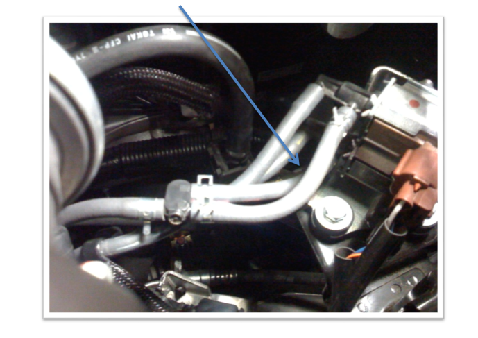
Disconnect this piece of vacuum line and use a long, thin hex key, or similar object, to push the restrictor pill out of the vacuum line. Reconnect the line with the pill removed. You are now ready to run COBB Stage2 mapping to its full potential.
Related content
Copyright 2025 © COBB Tuning Products LLC. All Rights Reserved. | www.cobbtuning.com