POR-001 Tuning Guide
- Will Trang
- Brandyn Mowat
- Former user (Deleted)

997.1 Twin Turbo
Tuning Guide and Table Definitions
This tuning guide is broken into the basic components of tuning a Porsche 997.1TT and the tables associated with each of these components. The guide outlines basic tuning strategies and defines tables for each major tuning category, such as boost control, fueling, and ignition timing.
Step 1 – What is the mechanical configuration of the vehicle?
The first step in tuning a Porsche 997.1TT is choosing a COBB Tuning Off-The-Shelf (OTS) calibration that most closely matches the mechanical components and modifications of the vehicle to be tuned
The Stage1 calibrations are designed for vehicles with no aftermarket parts at all. The Stage2 calibrations are designed for vehicles with an upgraded turbo-back exhaust system. This major difference in configuration impacts the pumping efficiency of the motor and critically impacts all major aspects of tuning (boost, fuel, and ignition).
Step 2 – What fuel is the vehicle using?
Note that COBB Tuning offers calibrations for three different fuels: 93 octane (98 RON), 91 octane (95 RON), and ACN91 (91 octane from Arizona, California, or Nevada). Higher octane ratings indicate higher quality fuel that burns more slowly and can support higher cylinder pressure. This difference in fuel will determine how the car is tuned. Higher octane fuels support more ignition timing, higher boost levels, and leaner air-to-fuel mixtures compared to lower octane. Using a map designed for high octane with low octane fuels can result in damage to the motor.
Step 3 – What type of air intake is on the vehicle?
The 997.1TT utilizes a mass air flow (MAF) sensor located downstream to the air filter and before the turbo to measure the amount (mass) of air entering the motor. This air flow measurement is CRITICAL for boost control, ignition timing, and fuel. This sensor reports the amount of air entering the motor, which is used to determine load. Many tables inside the ECU use Load and RPM as their axes. Therefore, it is important that the car is free of leaks of any kind before or after the MAF to be sure of proper running condition.
Step 4 – Calibration refinement on a chassis dynamometer.
A: Perform initial testing at low boost.
After selecting the most appropriate initial calibration, prepare to test and refine the calibration on a chassis dynamometer. When creating a custom tune, it is best to begin testing under low load conditions by lowering values in the map Target Cylinder Filling and Maximum Duty Cycle of the Boost Pressure Regulation.
B: Connect the Accesstuner software to the Accessport equipped 997.1TT
Open the selected starting calibration in the Accesstuner software then configure the Accesstuner software to connect to your vehicle. Attach the OBDII connector to the vehicle and, to your Accessport (if applicable), then connect the associated USB cable to your computer. Press "Ctrl+F" to configure the program. Select the directory in which to store your data logs under the "Logging" tab.
C: Log critical engine parameters while testing.
Accesstuner software allows the user to sample and record critical engine parameters including sensor information and commanded engine function. Open Accesstuner and load the calibration currently flashed to the vehicle. Attach the OBDII cable to the vehicle and the computer. Press "Ctrl+F" to configure the logged parameters in the "Log List" tab, and those displayed in the Accesstuner "Dashboard" through the "Gauge List" tab. The Dashboard, a screen that reports active engine and sensor parameters, can be accessed by pressing "Ctrl+B." It is critical to actively monitor the condition of the motor during tuning and this screen is the single best way to do so. These data monitors allow the tuner to determine if a calibration is performing correctly. Accurate and deliberate assessment of logged parameters is the only way to avoid conditions that may damage the motor.
If more than 12 parameters are selected at any one time, the logging can slow down. The Porsche can log 20 parameters around 20 Hz, so while still pretty fast, the less non-essential parameters the better.
D: Tuning for appropriate Air to Fuel Ratios (Lambda)
The ideal air to fuel ratio (AFR) depends upon fuel quality, engine design, fueling model (port injection, DISI, diesel, etc.), heat exchanging abilities, and other variables. Higher octane fuels are more stable at higher cylinder pressures, and are more resistant to preignition. Leaner AFRs can produce higher power, but also create more heat that may lead to unsafe preignition. Lower octane fuels, such as 91(95 RON) and ACN91 (Arizona, California and Nevada 91 octane), are less resistant to detonation and require a richer (fewer parts air per parts fuel) AFR for safer operation. Richer AFRs produces less heat, protect against detonation due to a cooling effect of the excess fuel and usually produce less power. We have found that the 997.1TT motor is tuned on the leaner side from Porsche. After some initial testing we have found that just by richening the fuel target, the car picked up power. So we suggest a target AFR of 11.4:1 or a Lambda of around .78.
Air to fuel ratios for these vehicles are directly impacted by several tables. The Porsche fuel control system operates a closed loop control strategy. This means that the car runs a set of wideband air fuel sensors, and is constantly adjusting the fuel targets based on a collection of variables. The fuel target under wide open throttle is dictated by the Target Lambda Driver Demand Map. Setting a target in this table will yield the Air Fuel desired, as long as some of the others conditions are correct.
Since the car uses a closed loop system to control fuel, the ECU is constantly monitoring and adjusting short term and long term fuel trims. You can make changes to the short term corrections by adjusting the Fuel Correction Maps. These maps are dependent on valve timing to determine which map is being used at which time. They are a basic multiplier set up so 1.00 = 0 in terms of percentage of a correction. Anything above 1.00 I.E. 1.10 is adding fuel, so in this case it would be an additional 10% fuel, .9 would be a -10% correction.
A fuel mixture that is too lean will contribute to uncontrolled combustion, excessive heat, detonation and possible engine damage. The objective is to run the car at the richest air to fuel mixture possible that does not sacrifice power. Ultimately, the best air to fuel can only be determined in concert with changes to ignition timing. For example, some a comparatively rich air to fuel mixture can be run with more ignition timing than a leaner mixture. This combination may produce higher power than a lean mixture with less ignition timing. Generally speaking, the air to fuel and ignition timing combination that produces the best power while minimizing heat is the desired calibration. Of course, this ideal is not limited to ignition timing and fuel, but is also a balance of variable cam timing and boost pressure.
E: Tuning Ignition Timing
The ignition control strategy in the Porsche 997.1TT is very dynamic and has a lot of contributing variables to determine the overall ignition timing value. Since the car is always trying best to calculate an overall best efficiency, it does this for ignition timing by using the optimal ignition timing maps and using a target lambda (ʎ) = 1 as a base for the efficiency. Additive corrections are made and form a variable in the ECU that is "optimal timing." This is the basis for all the ignition calculations in the car. The Porsche uses a strategy of two states of cam timing as well. These points will dictate which of the ignition timing maps are used and when. The actual ignition timing uses some additional variables and then comes to the conclusion of ignition timing based on the difference between the optimal ignition maps and the base ignition timing maps. We recommend not changing the optimal ignition timing maps and changing the base tables instead, as these are more realistic ignition timing values, and will blend with the optimal ignition timing maps. Most of the timing changes in tuning will be done in the Base Ignition Timing High Lift 1&2 maps.
F: Knock Control System
The knock control strategy on the Porsche 997.1TT is very complicated and uses individual cylinder knock control to make changes to the ignition timing at all times. The system is very sensitive and thus almost always has some sort of feedback. You can monitor knock retard and ignition correction in each cylinder. This is the best way to check for detonation, and to ensure a safe running vehicle. The closer to 0 the better, since it is dynamic it will also add timing, but if it sways into the negatives (-1 degrees and below) this is the car registering detonation. Since the car is very dynamic it is made to be sensitive. If you are getting values past -6 degrees you will want to try and lower ignition timing, or add more fuel to try and see if you can bring the values back closer to 0. Running a race fuel will also help in getting the knock control values closer to zero.
If running built engines you can change the knock detection thresholds in the software. By raising these tables you are de-sensitizing the knock control system. THIS SHOULD BE DONE WITH GREAT CARE AS DOING THIS CAN RESULT IN ENGINE DAMAGE AS KNOCK CONTROL BECOMES LESS ACTIVE!!
Generally speaking, higher ignition timing supports higher torque and greater power. However, ignition timing should be increased with great caution. Higher timing yields are limited by fuel quality and the mechanical limitations of the motor due to higher cylinder pressure. Too much timing will produce knock sums when fuel quality is the limiting factor. When fuel quality is high, ignition timing should ONLY be added when its addition produces a substantive increase in torque and power. If increased timing does not increase torque, the extra cylinder pressure is simply producing unnecessary stress on engine components.
G: Porsche Torque Control Strategy, Boost Control and VTG Control
The Porsche Bosch ME7.8.1 ECU uses torque control to influence how the car behaves on power and off power. This system uses input from a wide variety of internal and external sensors to dictate how the car reacts in certain conditions. The boost control system works in this same manner, not by trying to use a "standard" boost control setup, but by trying to achieve a target cylinder filling value. This is dynamic and varies based on conditions, temperatures etc. Raising the Target Cylinder Filling table will generally equate to a rise in boost pressure.
This ECU uses various methods to control torque output, such as closing the throttle plate when the car overshoots a target torque table. So you will always want to monitor throttle plate opening as it is a way for the car to lower the torque output. Other methods include lowering ignition timing, or changing air fuel ratios. So you want to be sure that the car is optimally calibrated in all conditions.
From the factory the Porsche 997.1TT is equipped with VTG turbo chargers. These turbos are a bit different than the traditional turbo chargers most are accustomed to. Manufactured by Borg-Warner, these turbos don't use a standard wastegate to control the boost pressure regulation but instead control turbo pressure by channeling gas flow in the turbo by adjusting guide vanes. It can change the angle of these guide vanes thus it's able to change the geometry of the turbo chargers. It can maintain a turbo pressure earlier and can hold that pressure throughout the whole torque range.
This control rhetoric is implemented by the ECU and changes boost pressure to meet the cylinder filling targets set in some of the tables. There are also some VTG tables that will directly affect the boost pressure control such as Maximum Duty Cycle of Boost Pressure Regulation and Boost Pressure Regulation Pre Control VTG. These maps for example if increased towards redline will help to hold boost pressure, thus resulting in more power.
H: Tuning Variable Cam Timing (Vario-Cam Plus)
Porsche uses a variable cam timing system that changes cam duration at different engine speeds, but with Vario-Cam it also changes the valve lift dependent on cam phasing. This provides very good efficiency in all driving ranges as it can change lift using hydraulic tappets with a type of attachment pin. There are 3 lobes on the cam and the center is the "slow lift" the outer 2 lobes are the fast lift and pertain more to making more power and a higher lift. This helps to make more power through the power band. The cam timing can be changed in the software. In order to be see results from this type of tuning a chassis or engine dynamometer is required.
I: Boost Off The Line (BOTL)
Boost Off The Line for the 997.1TT is a custom feature which allows the user to build boost while on the stationary rev limiter. Please review the following tuning guide addendum located at the end of the guide for instructions on setup and examples
J: Integrating all tuning parameters for the ideal calibration
The ideal calibration for your Porsche 997.1TT is a combination of all major tuning areas outlined above. Generally speaking, the Porsche 997.1TT will make the most power when it runs a lean AFR with the maximum amount of ignition timing allowed by the ECU without detonating. However, the theoretical ideal of 12.5:1 air to fuel ratio and high ignition timing is not realistic for all configurations and fuels. Calibrations should be thoroughly tested on a chassis dynamometer, where the impact of tuning is easily measured, to determine if they are ideal for the vehicle, its mechanical components, and its fuel. For example, addition of ignition timing that does not result in increased torque is not ideal because it produces additional stress on engine components without a perceivable benefit. The same is true of boost and air to fuel ratio. If the vehicle can operate at a richer air to fuel ratio without losing power, it is ideal to do so. If increasing boost does not yield considerable power gain, the turbo may simply be out of its efficiency range and, in this scenario, less boost is actually more power. For a basic idea of ideal tuning parameters for your fuel type and mechanical configuration, examine the COBB OTS map notes.
K: Precautions:
Boost – The stock turbo chargers can produce boost levels in excess of 25 psi, which is enough cylinder pressure to cause engine damage if not tuned correctly. Be cautious when adjusting boost control parameters, particularly when any mechanical components of the boost control system have been altered from the factory configuration.
If using non-factory turbo chargers you will be required to run an aftermarket boost controller as the factory ECU has no way of accurately controlling a standard wastegate. The output from the ECU is around 250 Hz and standard boost control solenoids are generally around 30 Hz, so you will want to run an electronic boost controller of some kind.
Fuel – The stock fuel injectors are ~670cc. These vehicles have well designed fuel systems, but if run on ethanol fuel they will run out of injector on the stock injectors and fuel system. Stock fuel pressure is 3.8 bar in the Porsche so make adjustments accordingly.
Folder: Boost Control
Subfolder: Airflow Tables
Boost Pressure to Load Conversion Table
Table Description – This table will alter the relationship between boost pressure and load.
Tuning Tips – Generally leave this table stock.
Precautions and Warnings – Keep in mind load is one of the main references for Porsche engine management. Altering this will change many other main values such as Ign Timing, Fuel Demand, etc… as their load reference will change. If this table is altered be sure to reflect the same alteration percentage in Boost Pressure to Load Conversion Table Variant #1 as well.
Boost Pressure to Load Conversion Table Variant #1
Table Description – This table will alter the relationship between boost pressure and load.
Tuning Tips – Generally leave this table stock.
Precautions and Warnings – Keep in mind load is one of the main references for Porsche engine management. Altering this will change many other main values such as Ign Timing, Fuel Demand, etc… as their load reference will change. If this table is altered be sure to reflect the same alteration percentage in Boost Pressure to Load Conversion Table as well.
Maximum Diagnostic Airflow Limit
Table Description – Airflow limit based on Throttle Position and Engine Speed.
Tuning Tips – Stock turbo cars should not need to raise this value from stock, raise this value if you are getting airflow related DTCs with larger turbos.
Maximum Diagnostic Airflow Limit Variant 2
Table Description – Airflow limit based on Throttle Position and Engine Speed.
Tuning Tips – Stock turbo cars should not need to raise this value from stock, raise this value if you are getting airflow related DTCs with larger turbos.
Folder: Boost Control
Subfolder: Boost Control PIDs
Integral Control
Table Description – Integral control is the sum of the deviation from the target over time. The longer the time without movement toward the target will result in an increase in integral control.
Tuning Tips – Increasing this will increase the reaction time but may increase the likely hood in overshooting the target.
Proportional Control
Table Description – Proportional feedback of the boost control error system.
Tuning Tips- You can modify this value to more or less aggressive depending on how bad of boost error you have, or if the error control feedback is too aggressive, or not aggressive enough.
Folder: Boost Control
Subfolder: Torque Limits
Maximum Indicated Engine Torque
Table Description- Torque limiter that is correlated to percentage.
Tuning Tips- Raise this to be sure not to hit it as a limit.
Maximum Indicated Engine Torque for Torque Normalization
Table Description- Torque limiter that is correlated to a physical engine torque in either ft. /lbs or Nm.
Tuning Tips- Raise this to be sure not to hit it as a limit.
Maximum Time for Activation of Overboost (Sport Mode)
Table Description- Timer to active overboost.
Tuning Tips- Raise this for increased overboost time.
Maximum Time for Torque Increase due to Overboost (Sport Mode)
Table Description- Timer for torque increase when hitting the sport mode button.
Tuning Tips- Raise this if you want the overboost feature to be active for longer.
Torque Limiting Table
Table Description- A torque limit map. The map is already very high and in most cases will not need to be raised.
Tuning Tips- Raise this if running into any type of throttle closure, especially in cars with aftermarket turbo chargers. This map is already very high so it just needs to be maxed out.
Folder: Boost Control
Subfolder: Torque Tables
Engine Torque Drag
Table Description- Maximum amount of engine drag allowed.
Tuning Tips- If raising power levels you will need to increase this table in order for there to be no complications with torque control. If you are experiencing stalling with lightened flywheel/rotating assembly modifying these tables in idle areas will help.
Engine Torque Drag Variant 2
Table Description- Maximum amount of engine drag allowed. This is a variant table and should be raised in the same proportion as Engine Torque Drag.
Tuning Tips- If raising power levels you will need to increase this table in order for there to be no complications with torque control. If you are experiencing stalling with lightened flywheel/rotating assembly modifying these tables in idle areas will help.
Maximum Indicated Torque
Table Description- This is a 2D table that is one of the torque control checks.
Tuning Tips- If raising power levels you will need to increase this table in order for there to be no complications with torque control.
Maximum Indicated Torque- Variant 2
Table Description- This is a 2D table that is one of the torque control checks. It is the same as the other Maximum Indicated Torque Table.
Tuning Tips- If raising power levels you will need to increase this table in order for there to be no complications with torque control.
Minimum Engine Torque
Table Description- Minimum amount of engine torque allowed.
Tuning Tips- Helpful to raise if running cars with big cams or light weight clutch components as it can help to keep cars from idle hunting.
Optimum Engine Torque
Table Description- This is one of the main maps for the torque control strategy. It is used in maximum torque efficiency calculation as well. This value works directly with the map, Target Cylinder Filling.
Tuning Tips- This table needs to be increased if you want to increase boost pressure. Because the ECU works on a torque based boost control strategy, raising this table will also raise boost pressure, as long as the Target Cylinder Filling map is raised as well. You want to try and make a linear change to both tables to ensure that the car runs correctly.
Target Cylinder Filling
Table Description- This table dictates the target load value. Raising this table generally requires the Optimum Engine Torque map to be raised as well. Otherwise a conflict with the torque control strategy will arise and the car will try and apply torque error correction. This table is one of the key proponents to increasing power. Increasing this table has a direct effect on increased boost pressure. Generally speaking, as target cylinder filling increases then more boost pressure is required.
Tuning Tips- Raise this value if you want to increase power, as this table has a direct correlation with the target torque strategy.
Precautions and Warnings – Be sure not to go too high without making appropriate changes to other limit tables, or else the car will run into errors.
Torque Limit at High Exhaust Gas Temperatures
Table Description- This is a torque limiter that is active at high exhaust gas temperatures.
Tuning Tips- This trim can become active on cars that may be running a bit rich, or have restrictive exhaust systems. We recommend raising this or maxing it out if you feel it is becoming an issue, or if you are running into a torque limiter of some kind and the car is closing the throttles.
Folder: Boost Control
Subfolder: VTG Control
Boost Pressure Regulation Pre Control of the VTG
Table Description – This is a pre control table for the VTG. This is a standard control table before the VTG motor handles the output.
Tuning Tips- Raise this table if you want to increase the amount of boost pressure possible using the stock boost control system. If you taper a bit more boost in towards redline it can help to hold boost pressure. In the GT2 especially you can make this value higher in the low end to get rid of the taper effect that comes with the cars stock, to give the car a sharp increase in torque in the lower RPM range.
Maximum Duty Cycle of the Boost Pressure Regulation
Table Description – This table dictates the max VTG duty cycle allowed in boost pressure regulation.
Tuning Tips- Raise this when attempting to raise boost and WGDC will not increase with load.
Maximum VTG Duty Cycle
Table Description – The maximum VTG cycle percentage allowed from 0-100%.
Tuning Tips- If trying to get as much out of the turbos as possible you may want to raise this value to 100%. Note that in order for this value to be hit you are going to have to make changes to the rest of the VTG tables.
Precautions and Warnings – Raising this value to 100% means that the turbos have the ability to run maximum boost pressure if the rest of the VTG tables are raised accordingly. Use caution if raising these tables.
Maximum Value of the WGDC Control for Upper Limit
Table Description – Maximum VTG Duty cycle based on RPM and load.
Tuning Tips- Raise these if you are hitting the wgdc ceiling set in this table.
Minimum VTG Duty Cycle
Table Description – The minimum VTG cycle percentage allowed from 0-100%.
Tuning Tips- If using different turbos you may want to make this 0 if boost control is not going low enough or set it to 0 if you would just like the duty cycle to be decreased lower than stock.
VTG Duty Cycle Correction Bank 1 vs. Bank 2
Table Description – This table dictates the difference in VTG duty cycle between the two banks.
Tuning Tips- This table is the offset for factory turbos. It will unlikely never need to be changed. You can monitor Turbo Duty Cycle Bank 1 and Turbo Duty Cycle Bank 2 to compare the actual difference.
VTG Duty Cycle Feed Forward Correction
Table Description – Additive VTG correction based on boost pressure.
Folder: Boost Control
Base Boost Pressure for Basic Elevation (Ambient Pressure)
Table Description- Basic airflow estimations at differing elevations.
Tuning Tips- Raise this value if increasing the boost pressure, as to not set off any boost control errors.
Compressor Ratio to Protect Against Over speed of the Turbocharger
Table Description- This is another threshold to protect against turbo over speed. Past this ratio the ECU will take measures to slow the turbo down.
Tuning Tips- Raise this value if increasing the boost pressure, as to not set off any boost control errors.
Correction Factor for Maximum Load Limitation
Table Description – This table is a multiplier for the max load limit the ECU can see. If you increase this it will effectively increase the amount of load the ECU can see without any adverse effects.
Tuning Tips – None at this time.
Delta Load Overboost Active
Table Description – This is a multiplier table that allows an active increase in the load based on a percentage if overboost or sport mode, is active.
Tuning Tips – Raise this table if increasing boost pressure to ensure that no errors are triggered.
Delta Pressure Deviation-Base Boost Pressure for Altitude
Table Description – This is a deviation error for the base boost pressure against the altitude. This needs to be raised if the boost pressure is increased due to the delta between the two will be too high and can trigger errors.
Tuning Tips – Raise this table if increasing boost pressure to ensure that no errors are triggered.
Factor for Torque Increase in Case Overboost is Active
Table Description – This is a deviation error for the base boost pressure against the altitude. This needs to be raised if the boost pressure is increased due to the delta between the two will be too high and can trigger errors.
Tuning Tips – Raise this table if increasing boost pressure to ensure that no errors are triggered.
Limit of Engine Speed to Trigger Overboost
Table Description – RPM limit that will trigger an overboost error.
Tuning Tips – Raise this table to be sure that the car does not throw an overboost error code if increasing boost pressure and the rev limit.
Maximum Allowable Pressure Ratio at the Throttle Plate for Boost Pressure Diagnosis
Table Description – The maximum amount of boost pressure based on RPM and throttle position before the throttle plate.
Tuning Tips- This value will need to be raised in order for there to be no errors when increasing the boost pressure.
Maximum Compressor Ratio (Turbocharger)
Table Description- This is the maximum compressor ratio of the turbocharger. Past this ratio the ECU will take measures to slow the turbo down.
Tuning Tips- Raise this value if increasing the boost pressure, as to not set off any boost control errors.
Maximum Duty Cycle of the Boost Pressure Regulation
Table Description – This is the maximum duty cycle of the amount of boost pressure regulation that the ECU will output.
Tuning Tips- Raise this table if you want to increase the amount of boost pressure possible using the stock boost control system. If you taper a bit more boost in towards redline it can help to hold boost pressure.
Maximum Indicated Torque for Over Power Protection, Overboost Active
Table Description – This table is an indicated torque number from 0-100%. This is a direct correlation to the amount of desired toque allowed. This is for Sport mode.
Tuning Tips- Raise this value if increasing the power level as it will raise the threshold of torque allowed when sport mode if active.
Maximum Indicated Torque for Overpower Protection
Table Description- This table is an indicated torque number from 0-100%. This is a direct correlation to the amount of desired toque allowed. This is for normal mode.
Tuning Tips- Raise this value if increasing the power level as it will raise the threshold of torque allowed in normal mode.
Substitute value for Maximum Pressure before the Throttle Body
Table Description- This is a max limit of boost pressure before the throttle body.
Tuning Tips- Raise this value if increasing the boost pressure, as to not set off any boost control errors.
Threshold Negative Deviation for Overboost Errors
Table Description – This is a pressure difference against the target cylinder pressure.
Tuning Tips- You will want to raise this error when raising the boost pressure so that any negative deviation will not cause any errors.
Upper Boost Pressure Range Check
Table Description – This is an upper range check for boost control. If actual boost pressure is greater than this table the throttles will close, generally after a shift. The manifold pressure reported will also default to ambient for a short time
Tuning Tips- You will want to raise this to about 3-5psi greater than your target boost pressure.
Folder: Boost Off The Line (BOTL) – Non GT2
Launch Control Timing
Table Description- Values placed in this table will add or subtract timing after all other timing calculations have been made. Y-axis is Vehicle Speed, X-axis is RPM.
Tuning Tips- Please see the BOTL tuning addendum at the end of the guide for a more in depth description of how to set up BOTL.
Precautions and Warnings – Using BOTL delays combustion while enabled, thus a dramatic increase of energy is released into the exhaust system and turbos. Added heat and pressures may decrease the longevity of these systems. Since this table takes the final ignition timing value after all compensations it is possible to surpass the lower or upper bound ignition timing limits. In our stock turbo testing we did not see much improvement in the cars ability to build boost past -35°.
Rev Limit Configuration
Table Description- Modifies the stability of the throttle while on the stationary rev limit
Tuning Tips- Please see the BOTL tuning addendum at the end of the guide for a more in depth description of how to set up BOTL.
Precautions and Warnings – If this value is increased dramatically it will cause sharp throttle changes which may result in unstable boost, turbulent air, and possible detonation.
Stationary Rev Limit
Table Description- RPM limit for when the vehicle is stationary. RPM is modulated via throttle position.
Tuning Tips- Set this value to your desired launch rpm. This can be set without using BOTL. If using BOTL see the tuning addendum at the end of the guide for a more in depth description of how to set up BOTL.
Folder: Brake Boosting
Delay Time for Limit when the Brake Pedal is Pressed
Table Description- Amount of delay to closing the throttles when the brake pedal is pressed down.
Tuning Tips- Increase this value to ensure that the throttle does not close when trying to use brake boosting. We suggest still leaving a limit on this as to ensure that the car cannot be run for too long in this mode and to ensure that there is a still a safety device in place in the event the throttle is stuck in the open position.
Precautions and Warnings – Modify this at your own risk!! This is a safety device and should only be modified with the knowledge of how to turn a car off in the event of a throttle malfunction!!
Maximum Throttle Angle with Brake Pedal Pressed
Table Description- Maximum throttle percentage allowed while the brake pedal is pressed.
Tuning Tips- Increase this value to ensure that the throttle does not close when trying to use brake boosting. We suggest still leaving a limit on this as to ensure that brake boosting cannot be run for too long of a time.
Precautions and Warnings – Modify this at your own risk!! This is a safety device and should only be modified with the knowledge of how to turn a car off in the event of a throttle malfunction!!
Minimum Engine Speed for Pedal Limit when the Brake Pedal is Pressed
Table Description- Maximum throttle percentage allowed while the brake pedal is pressed.
Tuning Tips- Increase this value to ensure that the throttle does not close when trying to use brake boosting. We suggest still leaving a limit on this as to ensure that brake boosting cannot be run for too long of a time.
Precautions and Warnings – Modify this at your own risk!! This is a safety device and should only be modified with the knowledge of how to turn a car off in the event of a throttle malfunction!!
Minimum Vehicle Speed for Pedal Limit when the Brake Pedal is Pressed
Table Description- Minimum speed the vehicle needs to be traveling in order to activate the throttle closure feature.
Tuning Tips- Increase this value to ensure that the throttle does not close when trying to use brake boosting. We suggest still leaving a limit on this as to ensure that brake boosting cannot be run at too high of a vehicle speed.
Precautions and Warnings – Modify this at your own risk!! This is a safety device and should only be modified with the knowledge of how to turn a car off in the event of a throttle malfunction!!
Folder: Cam Timing Tables
Intake Cam Timing
Table Description- Degrees BTDC (before top dead center) that the intake cam opens and closes.
Tuning Tips- Modify this table to try and achieve optimum cylinder filling and to help increase volumetric efficiency.
Intake Cam Timing High Valve Lift
Table Description- Degrees BTDC (before top dead center) that the intake cam opening when the car is using the high valve lift mapping. This is typically when trying to achieve maximum performance at wide open throttle.
Tuning Tips- Modify this table to try and achieve optimum cylinder filling and to help increase volumetric efficiency.
Folder: Compensations
Air Temperature Hot Limit
Table Description- This 1D value is the limit of the intake air temp threshold before the ECU considers the air temps to be too high and starts to aggressively trim out power.
Tuning Tips- You can increase this temp if you are on the dyno and trying to calibrate a car and don't want as much compensation to effect the tuning. If you are always past this on the road the car may also be in need of an intercooler upgrade.
Precautions and Warnings – Raise this table with caution as it will change when the intake air temp compensations come in which are a good thing if the temperature is indeed too hot.
Intake Air Temp Compensation Over the Throttle Plate
Table Description – This table accounts for the density of air vs. temperature, and outputs fuel adjustments based on charge air temp.
Tuning Tips – Leave this stock unless you are getting drastic fuel corrections as intake temps increase/decrease.
Target Exhaust Gas Temp 1 & 2.
Table Description- These tables are exhaust gas temperature targets. Past this the car will try and trim the values back down by implementing methods such as closing throttles.
Tuning Tips- You can increase this temp if you are making big power and the exhaust gas temperature appears to be too high. This is a modeled temperature so the actual temperature values can vary. We suggest having a good way to make sure to measure EGT if you are unsure of the actual temperature.
Folder: Fuel Tables
Subfolder: Individual Cylinder Fuel Correction
Individual Cylinder Fuel Addition Cylinder 1-6
Table Description – This table alters the percentage change of fuel per cylinder based on RPM.
Tuning Tips – Lower value to lean out the cylinder, Raise to add fuel. Default values are 1.00 for each cylinder.
Precautions and Warnings – Since Porsche does not have individual cylinder fuel corrections/o2 sensors and only have o2 sensors to monitor each bank, richening up one cylinder may result in the leaning out of the other two due to bank corrections, or vice versa.
Individual Cylinder Fuel Addition at Idle Cylinder 1-6
Table Description – This table alters the percentage change of fuel per cylinder based on RPM at idle.
Tuning Tips – Lower value to lean out the cylinder, Raise to add fuel. Default values are 1.00 for each cylinder.
Precautions and Warnings – Since Porsche does not have individual cylinder fuel corrections/o2 sensors and only have o2 sensors to monitor each bank, richening up one cylinder may result in the leaning out of the other two due to bank corrections, or vice versa.
Cold Start Enrichment
Table Description – This table references temp and is an additional fuel percentage above what is requested from the ECU when the car is warming up.
Tuning Tips – Raise this table if you are experiencing cold start issues. This table can be very useful in helping to start on ethanol fuels.
Cold Start Enrichment- Weighting Factor
Table Description – This table references engine load and engine speed. This table is an additional fuel percentage above what is requested from the ECU when the car is warming up.
Tuning Tips – Modify this table if you are experiencing partial throttle issues related to fueling. This can be helpful on ethanol fuels to take care of any drivability issues.
Cold Start Enrichment- Load Dependent
Table Description – This table references engine load and engine temperature. This table is an additional fuel percentage above what is requested from the ECU when the car is warming up.
Tuning Tips – Modify this table if you are experiencing partial throttle issues related to fueling. This can be helpful on ethanol fuels to take care of any drivability issues.
Delay Time Until Lambda Driver's Desired Active
Table Description – Delay In time before fueling switches to target the output of the Target Fuel Driver Demand table
Tuning Tips – Lower or raise this value if you are engaging the Target Fuel Driver Demand table to sooner or later than desired Precautions and Warnings – None at this time.
EGT Temp to Switch to Lambda for Component Protection Fuel Map
Table Description – Above this EGT value the Target Fuel Map for Component Protection will engage.
End of Injection Angle
Table Description – This table helps to adjust the end of injection timing for the fuel injectors. The z data values are in degrees BTDC. The idea of this table is to inject fuel with the intake valve open for best efficiency. This is changed to try and increase atomization but sometimes this can be hard. It is also sometimes best to inject fuel onto the closed inlet valve if you feel like the injectors you are using are not atomizing fuel well. This can help atomize the fuel in the intake port but fueling accuracy does decrease. This can also be helpful in starting cars as well. These tables are also useful if you have a car with larger injectors and they are producing black smoke under wide open throttle.
Fuel Correction Adaption Range #1 - #4 (B742 Roms Only)
Table Description – Table adjusts the reaction of fuel corrections in the B742 Roms.
Tuning Tips – B742 Roms do not use the same PID for fuel control as the other 997.1TT Roms(B730, B740, etc…) If you are seeing large oscillations (see image below) in AFR and STFT during higher RPM attempt to lower the values at higher RPM to match the values lower in the table. Taking values from the 3000RPM row and putting them in the 6000RPM row and interpolating vertically works well. Some further fine adjustment may need to be made but this is a great starting point to fix the oscillation. Recommend doing this to tables 1-4 if needed. You can see below the large oscillations. This is a rather extreme case where AFR (yellow and green) is jumping from 10.5:1 to 13:1 in a tenth of a second. STFT (Red and White) are doing the inverse, swaying as much as 40% from one extreme to the other, trying to bring AFR back to target. However, the correction overshoots and the cycle compounds. 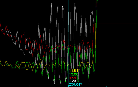
Precautions and Warnings – If this value is lowered to low corrections may take too long to occur if they are needed. E.g. The car is leaning out and STFT take too long to start adding fuel.
Fuel Correction Range #1 - #3 (B742 Roms Only)
Table Description – Table adjusts the reaction of fuel corrections in the B742 Roms.
Tuning Tips – B742 Roms do not use the same PID for fuel control as the other 997.1TT Roms(B730, B740, etc…). If you are seeing large oscillations (see image above) in AFR and STFT during higher RPM attempt to lower the values at higher RPM to match the values lower in the table. Taking values from the 3000RPM row and putting them in the 6000RPM row and interpolating vertically works well. Some further fine adjustment may need to be made but this is a great starting point to fix the oscillation. Recommend doing this to tables 1-2 if needed.
Fuel Correction Map 1,2 and Variant 1,2
Table Description – These are the tables that help correct volumetric efficiency inconsistencies. If you need to get more fuel due to the fuel trims being off, then you want to make fuel changes in one of the four fuel correction maps. These maps are defined by injector open time and cam timing lift.
Injector Latency
Table Description – This table contains latency values used to tell the ECU how much latency is needed to properly control the fuel injectors; the breakpoints are in battery voltage. All fuel injectors require a certain amount of "dead" time to fully open which is referred to as Injector Latency. The amount of latency an injector requires is dependent on several factors, such as the size of fuel injectors, viscosity of fuel, manifold pressure, and fuel pressure. Lower battery voltage requires increased injector latency (dead time). Likewise, higher fuel pressure may also increase injector latency. The data in this table is represented in milliseconds. A higher value will open the fuel injector sooner, thus the total IPW will be greater; a lower value will open the fuel injector later, thus the total IPW will be less.
Tuning Tips – Most fuel injector manufacturers will be able to provide you with injector latencies by voltage. The drivers used to develop these latencies may be different than the injector drivers in the stock ECU, so further modification from the published values may be necessary and you should not be concerned if your final values differ from manufacturer documentation.
One way to find the correct latency (or at least the latency that works best with the injector drivers in the ECU and your particular injectors) is to begin with stock fuel pressure and the stock intake system, then set the proper scale value for the injectors you are using based off the scalar calculation. Once you have established a proper injector scalar value, start the engine and let the car warm up (coolant temperature between 170-200˚ F and intake air temperature +/- 15 degrees F of ambient temperature) then re-set the ECU so your fuel trims start at zero. Then, start the vehicle again and watch the SUM of your fuel trims, STFT + LTFT. If you see that the SUM of your fuel trims (STFT + LTFT) is positive, add injector latency until you see the SUM of your fuel trims come closer to zero. You will have to test this throughout the operating range of the engine. Try to avoid sudden throttle movements during this process to avoid corrections based on the Tip-in Enrichment tables. If you see that the SUM of your fuel trims is negative, reduce injector latency until you see the SUM of your fuel trims come closer to zero. Again, you will have to test this throughout the operating range of the engine - the entire MAF curve. Try to avoid sudden throttle movements during this process to avoid corrections based on the Tip-in Enrichment tables.
This is part of a calibration process that will bring you closer to the ideal settings necessary to properly control your fuel injectors. Please take into account that you will most likely have to calibrate the fuel correction maps to get the trims where you want them at different operating conditions.
Injector Scaling
Table Description – This table contains a singular value used to represent the fuel injector size or flow rate. Any changes to this value will affect ALL tables within the ECU related to fuel delivery and load calculations. When using stock injectors with gasoline, this value DOES NOT need to be altered. When adjusting this value, a lower number represents a LARGER injector, whereas a larger scale value will represent a SMALLER injector. This value in the Porsche is a factor of total opening time. A larger injector will need less time open to supply the same amount fuel, hence the smaller number for a larger injector.
Tuning Tips – In order to calculate the injector open time Porsche uses a large equation to come to the final value. In this equation they calculate air density as well as a slew of other variables. One of these variables is calculating an injector constant with n-heptane. Since some injector companies don't use this as a calibration medium anymore, this can sway the final result of the injector scaling since the density of the two fluids is different. So depending on injector manufacturer you may need to adjust the scaling either up or down to come to a value that is close according to the fuel trims.
With that being said here is the best way to come up with the proper value range for larger injectors:
Y= 44.0901/X so in order to get a new injector constant value divide 44.0901 by your injector size.
Example- Injector Constant= 44.0901/1000(cc)
Injector Constant= .04409 or about .045.
Lower Diagnostic Threshold for Lambda Control
Table Description – This data value is the lower range of the fuel system adaption. It can adapt up to 20% negative. .8= -20%
Tuning Tips – Lower this if you feel that there needs to more room for the ECU to adjust fuel trims in the negative direction.
Precautions and Warnings – None at this time.
MAF Correction
Table Description – This table is used to correct for fluctuations in the MAF signal due to turbulent airflow. This can prove to be useful for cars that are using different intakes that have different size or geometry in relation to piping.
Minimum Injector Pulsewidth
Table Description – This table is the lowest injector pulse width the ECU will allow the injector to operate at.
Tuning Tips – If running an injector is very large like a 2000cc injector, then you may need to increase this value to make sure that the deviation of the injector at low pulse widths is within range. For example if using an Injector Dynamics 2000cc Injector then you would want to raise this value to around 1.0ms or something similar to make sure that the deviation is within a reasonable percentage.
Multiplication Factor for Component Protection Based on EGT
Table Description – This table is used to change the Lambda target by a percentage based on Exhaust Gas Temperature.
Tuning Tips – Values in this table can be used as a safety to add fuel in case of high EGT's.
Target Fuel Driver Demand Map
Table Description – This is the lambda target at wide open throttle that you are commanding from the car. The ECU will do its best to try and reach this target by using short term and long term fuel trims as well as data from other sensors.
Tuning Tips – You want to ensure that the lambda target is safe under wide open throttle and not too lean as this can cause damage while at the same time ensuring that it is not too rich as it will hinder performance. We recommend a value of around .78-.81 under full load.
Target Fuel Map for Component Protection; Target Fuel Map for Component Protection 2
Table Description – These two tables are used as protection maps incase temperature limits are reached. They are used as a precaution to cool down the cylinder by adding more fuel than what is requested in the Target Lambda Driver Demand Map. There are two of these maps, one for each bank. They will get used when modeled temperatures get too high in some of the sub systems (EX-EGT)
Tuning Tips – Set these to where you would want a safe air fuel mixture. Avoid setting these too rich as overly rich conditions and retarded ignition timing can cause high EGT's. Also try to set them the same so that you do not have varying conditions from one bank to another.
Upper Diagnostic Threshold for Lambda Control
Table Description – This data value is the upper range of the fuel system adaption. It can adapt up to 20% positive. 1.2= 20%
Tuning Tips – Raise this if you feel that there needs to more room for the ECU to adjust fuel trims in the positive direction.
Folder: Idle Control
Target Idle Table; Target Idle Table 2
Table Description – Target idle requested for the car based on gear and coolant temperature. Set this higher if the car has cam shafts, or generally just need the idle to be higher.
Folder: Ignition Timing
Subfolder: Individual Ignition Cylinder Trims
Pilot Threshold for Individual Cylinder Trims
Table Description – Engine Speed must be above this value for individual cylinder timing trims to take effect
Individual Cylinder Ignition Trim 1-6
Table Description – Ignition timing can be added and subtracted on a per cylinder basis
Precautions and Warnings – If timing is added or subtracted here it will impact the timing corrections made under the knock cyl. monitor depending on which cylinder you have made the adjustments. The ECU will still pull timing if it sees knock in that cylinder. I.E.: You remove 1° of timing from cylinder 6 above 5200RPM, knock cyl 6 monitor will now always read -1 or lower above 5200RPM. Not due to actual knock retard but do to your demanded removal of that 1° in that particular RPM range.
Base Ignition Timing High Valve Lift 1&2; Base Ignition Timing Map 1&2
Table Description – These are the base ignition timing tables. These are the lower end of the timing maps that are used. Most of the time the timing is close to these values if the knock control system is active. These tables get selected based on cam timing.
Tuning Tips – Make the same changes you want to be made to all 4 of these timing tables so you know the timing will be consistent in all operating ranges.
Ignition Angle at Start
Table Description – This is an ignition correction at start based on coolant temperature.
Minimum Ignition Angle Variant 1-4
Table Description – This dictates the minimum ignition timing value
Tuning Tips – If using BOTL see addendum at the end of this document and review the importance of these tables.
Folder: Knock Control
Delta Ignition Angle in Continuous Knocking Bank 1, Bank 2
Table Description – Timing amount to be pulled with continuous knocking. If knock continues the delta will increase in increments of this value.
Precautions and Warnings – This impacts the rate that the engine will compensate for knock (detonation) and can compromise the safety of the engine if changed too significantly. Modify at your own risk!
Knock Detection Threshold Cylinder 1-6
Table Description – These thresholds are made to determine when the knock control system becomes active. Raising these thresholds will make the car less likely to pull timing when it hears something it deems as a knock event. Use this on built motors when the harmonics of the engine can change the amount of noise the knock sensor deems as knock, when in fact, it is just engine noise. The numbers are for each individual cylinder.
Maximum Timing Retard
Table Description – This is the maximum amount of timing that can be pulled out when the knock control is active throughout the RPM range.
Tuning Tips – – Change this if you feel that the car is pulling too much timing or too little timing depending on the knock event. USE THIS WITH GREAT CAUTION!
Timing Reduction per Knock Event
Table Description – The amount of timing retard in degrees that gets pulled during each knock event.
Tuning Tips – Change this if you feel that the car is pulling too much timing or too little timing depending on the knock event. USE THIS WITH GREAT CAUTION!
Timing Refresh Rate Post Knock Event
Table Description – This is a raw value for how fast timing comes back in after a knock event.
Folder: Limits
Engine Speed Limiter 2
Table Description- Maximum engine speed in RPM.
Tuning Tips- Increase this value to raise the RPM cut.
Engine Speed Limiter 3
Table Description- Maximum engine speed in RPM.
Tuning Tips- Increase this value to raise the RPM cut.
Engine Speed Limiter with Speed Signal Error
Table Description- Maximum engine speed in RPM if there is a speed signal error.
Tuning Tips- Increase this value to raise the RPM cut.
Engine Speed limit for automatic transmission with Speed Signal Error
Table Description- Maximum engine speed in RPM if there is a speed signal error per gear.
Tuning Tips- Increase this value to raise the RPM cut.
Vehicle Speed Limit
Table Description- Maximum engine speed in RPM if there is a speed signal error per gear.
Tuning Tips- Increase this value to raise the RPM cut.
Folder: Sensor Calibration
Gradient for Pressure Sensor Before Throttle
Table Description – This is the PUT(Pressure Up Throttle) sensor gradient. This needs to be changed if using a larger than stock map sensor. Consult the MAP sensor manufacturer for the values to be put in this table.
Tuning Tips – If you are using a COBB 3 Bar MAP Sensor set this value at 658.83 hpa/v.
MAF Sensor Scaling
Table Description –This is the scaling table for the mass air flow sensor. If running an aftermarket intake you can make changes to this to make sure that the car is running properly. This calibration is crucial for the car to run correctly if using the standard mass air flow based tuning method.
Tuning Tips – None at this time.
Maximum Voltage Value for Diagnostic Pressure Sensor Before Throttle
Table Description – This is the maximum voltage which can be seen before a CEL is triggered for sensor out of range.
Tuning Tips – Try raising this if you are hitting the voltage limit.
Minimum Voltage Value for Diagnostic Pressure Sensor Before Throttle
Table Description – This is the minimum voltage which can be seen before a CEL is triggered for sensor out of range.
Tuning Tips – Try lowering this if you are hitting the voltage limit, especially with aftermarket MAP sensors.
Offset for Pressure Sensor Before Throttle
Table Description – This is the map sensor offset. Change this value if using larger than stock MAP sensor. Consult the MAP sensor manufacturer for the values to be put in this table.
Tuning Tips – If you are using a COBB 3 Bar MAP Sensor set this value at -63.59hpa or -.92psi depending on the units selected in ATR/ATP.
Folder: Throttle
Permissible Torque from Throttle Pedal for Torque Limit- Normal Mode
Table Description- This table is an overall torque output based on throttle position. It is another of the main systems that controls torque output for Normal Mode
Tuning Tips- This table will have to be raised, or potentially maxed out, if running a substantial amount more boost.
Permissible Torque from Throttle Pedal for Torque Limit- Normal Mode- Variant 2
Table Description- This table is an overall torque output based on throttle position voltage. It is another of the main systems that controls torque output for normal mode.
Tuning Tips- This table will have to be raised, or potentially maxed out, if running a substantial amount more boost.
Permissible Torque from Throttle Pedal for Torque Limit- Sport Mode
Table Description- This table is an overall torque output based on throttle position. It is another of the main systems that controls torque output for Sport Mode.
Tuning Tips- This table will have to be raised, or potentially maxed out, if running a substantial amount more boost.
Permissible Torque from Throttle Pedal for Torque Limit- Sport Mode Variant 2
Table Description- This table is an overall torque output based on throttle position voltage. It is another of the main systems that controls torque output for Sport Mode.
Tuning Tips- This table will have to be raised, or potentially maxed out, if running a substantial amount more boost.
Target Throttle Angle vs. Air Flow
Table Description- Target throttle table dictated by throttle position (TPS) and cylinder filling
Tuning Tips- Increase this table if you want the car to be a bit more responsive in the low end in terms of pedal response.
Torque Request from Accelerator Pedal- Normal Mode
Table Description- This table is a percentage of torque applied based on pedal position. This is for normal driving mode, non-sport mode.
Tuning Tips- Raising this table will make the pedal percentage more aggressive. It can be used to make the car feel more responsive. This table is for normal mode, NOT for Sport Mode.
Torque Request from Accelerator Pedal- Sport Mode
Table Description- This table is a percentage of torque applied based on pedal position. This is for Sport Driving Mode.
Tuning Tips- Raising this table will make the pedal percentage more aggressive. It can be used to make the car feel more responsive. This table is for SPORT mode.
Folder: Miscellaneous
Delay Time Reset for Sport Start
Table Description- Timer to reset sport start.
Tuning Tips- Decrease this value to decrease the amount of time before sport start resets.
Pedal Value Threshold Sport Start
Table Description- Overall pedal position to enable sport start mode.
Tuning Tips- Decrease this value to decrease the amount of time before sport start resets.
Toggles (Base)
The following values can be checked in the toggles section of the software to disable diagnostic errors.
Boost Pressure Error Delete 1- Checking this box will shut off any errors associated with boost pressure control. Check this box if removing stock VTG motors and/or are getting throttle closures due to the boost control system.
Boost Pressure Error Delete 2- Checking this box will shut off any errors associated with boost pressure control. Check this box if removing stock VTG motors and/or are getting throttle closures due to the boost control system.
VTG Code Disable- Checking this byte will shut off the diagnostic process for the VTG actuators.
VTG Delete 1 and 2- By checking both the VTG Delete 1 and VTG Delete 2 box you will disable the diagnostic routine for the VTG motors. This is useful only for those with upgraded turbos that want to remove the VTG motors from the car. Leave these on if tuning a VTG equipped car.
Boost Off The Line Addendum (BOTL)
Boost Off The Line (or BOTL) is a tunable custom COBB feature that works by increasing the pressure output of the turbochargers prior to, and during a launch. It does so by delaying ignition timing which postpones the combustion process, thus "stealing" some of the combustion energy that would generally contribute to driving the piston. Diverting exhaust gas past the exhaust valves to drive the turbine side of the turbocharger instead. Since not much relative work is required to keep a motor free spinning we take some of that and utilize it to aid in the earlier production of boost. The change in the moment of inertia of the spinning engine during a launch is relatively unchanged, but a noticeable increase in boost response and torque available during a launch are dramatically increased.
This increased energy in the exhaust comes in the form of pressure and heat. The increased pressure and heat will have an adverse impact on the longevity of the turbos and exhaust system. BOTL should be used at your own risk!
Launch Control Timing
Table Description- Values placed in this table will add or subtract timing after all other timing calculations have been made. Y-axis is Vehicle Speed, X-axis is RPM.
Tuning Tips- With this table set at 0 bring the car up to the desired launch RPM dictated by the Stationary Rev Limit. Note what the timing values are. Place values in the table that will bring ignition timing down to your desired target.
Example: With Launch Control Timing set at 0 you are seeing an ignition value of 30° while on the stationary rev limit. If you wanted to target -30° during the stationary rev limit put -60° in for the values at the correlating speed and RPM – See our BOTL OTS Map for an example
Precautions and Warnings – Using BOTL delays combustion while enabled, thus a dramatic increase of energy is released into the exhaust system and turbos. Added heat and pressures may decrease the longevity of these systems. Since this table takes the final ignition timing value after all compensations it is possible to surpass the lower or upper bound ignition timing limits. In our stock turbo testing we did not see much improvement in the cars ability to build boost past -35°.
Rev Limit Configuration
Table Description- Modifies the stability of the throttle while on the stationary rev limit.
Tuning Tips- If you are experiencing erratic throttle while on the stationary rev limit try to lower these values. Most likely the factory values will not need to be changed.
Precautions and Warnings – If this value is increased dramatically it will cause sharp throttle changes which may result in unstable boost, turbulent air, and possible detonation.
Stationary Rev Limit
Table Description- RPM limit for when the vehicle is stationary. RPM is modulated via throttle position.
Tuning Tips- Set this value to your desired launch rpm.
Minimum Ignition Timing Variant 1-4
Located in Ignition Timing Folder
Table Description- Minimum Ignition value allowed.
Tuning Tips- Set these values for all four tables to the desired minimum ignition timing you wish to see during the stationary rev limit. Adjust these values only at the desired RPM and load where BOTL is impacted. Lowering these tables may retard ign timing on decel causing backfires and lethargic rev matching. It is wise to change them only in the proper load/rpm cells active during BOTL.
Precautions and Warnings – Adjust these values only in the load and RPM areas where the rev limit is active.
BOTL Setup
- Example of Stage 3 E85 Stock Turbo BOTL Setup for B730-5843 Stage3 E85 v100 BOTL B730-5843.ptm
Stationary Rev Limit
- Set your Stationary Rev Limit to your desired RPM. 4500RPM is a good starting point.
- Leaving all other BOTL and minimum ignition tables stock, take a datalog of the car while revving to the stationary rev limit for roughly 2-3 seconds. This step may need to be revisited as you add in boost since that will likely increase load.
- Review the log and take note of where the load, RPM, and ignition timing values settle – this will be useful in setting up the Minimum ignition tables (Step 2) as well as your Launch Control Timing Tables (Step 3).
Setting Up Minimum Ignition Tables
- Set the minimum ignition timing for all four Minimum Ignition Timing tables to the values that you wish to see while using BOTL. -30* is a good starting point. Put these values in the correlating cell as well as the ones adjacent, keeping in mind load will increase as ignition timing is removed.
Setting Up Launch Control Timing
- This is your main timing adjustment table for BOTL. The X-axis is RPM and the Y-axis is vehicle speed.
- This table adds or removes timing after the final timing value has been calculated.
- Changing the Axis values for more precise control is doable and highly recommended!
- EX: You noticed in the log you took in step one that your ignition timing on the stationary rev limit was +30°. If you wanted to target -30° with BOTL you would want to put -60° in the table for the correlating speed and RPM areas in Launch Control Timing.
- Flash in the changes to your tables and try the stationary rev limit again with the BOTL changes. Pay close attention to boost pressure. The example map above creates roughly 5psi at the 4500RPM limit with -30° of timing after being on the stationary rev limit for about 1.5 seconds. Staying on the limiter longer will generally produce more boost, with increased pressure, heat. The amount of heat and pressure produced by using BOTL is tremendous and may result in premature part failure if used repeatedly.
- Retard ignition timing in Launch Control Timing to increase boost pressure, advance timing to decrease boost pressure until the desired boost is achieved.
Setting Up Rev Limit Configuration
- This table should rarely have to be changed from factory. Lower the values if you notice unstable throttle while using BOTL.
- This Table is 2d with the axis being vehicle gear. 0 is reverse, 1 is neutral, 2-7 are 1st-6th gear. The values are a raw decimal which can be inputted from 0-255. We recommend only decreasing these values if you notice unstable throttle while BOTL is active. Increasing these values past stock may cause unwanted throttle fluctuations.
Individual Cylinder Fuel Addition Cylinder 1-6
Copyright 2025 © COBB Tuning Products LLC. All Rights Reserved. | www.cobbtuning.com