Porsche 991.2 / 718 Tuning Guide
- Brandyn Mowat


Tuning Guide
- 718 Boxster, Cayman
- 991.2 3.0l Carrera, Carrera S, GTS
- 991.2 3.8l Turbo, Turbo S
- 991.2 GT2 RS
991.2 Models
| Displacement | Compressor Size | Turbine Size | Boost Peak (Stock) | Apprx. Value New | Stock Tq / HP | |
|---|---|---|---|---|---|---|
| Base Carrera | 3.0l | 49mm | 45mm | 13 psi | $90k | 336/367 |
| Carrera S | 3.0l | 51mm | 45mm | 16 psi | $110k | 376/403 |
| Carrera GTS | 3.0l | 55mm | 48mm | 18 psi | $138k | 409/423 |
| Turbo | 3.8l | 58mm | 50mm (VTG) | 18 psi | $180k | 480/490 |
| Turbo S | 3.8l | 62mm | 50mm (VTG) | 20 psi | $200k | 525/515 |
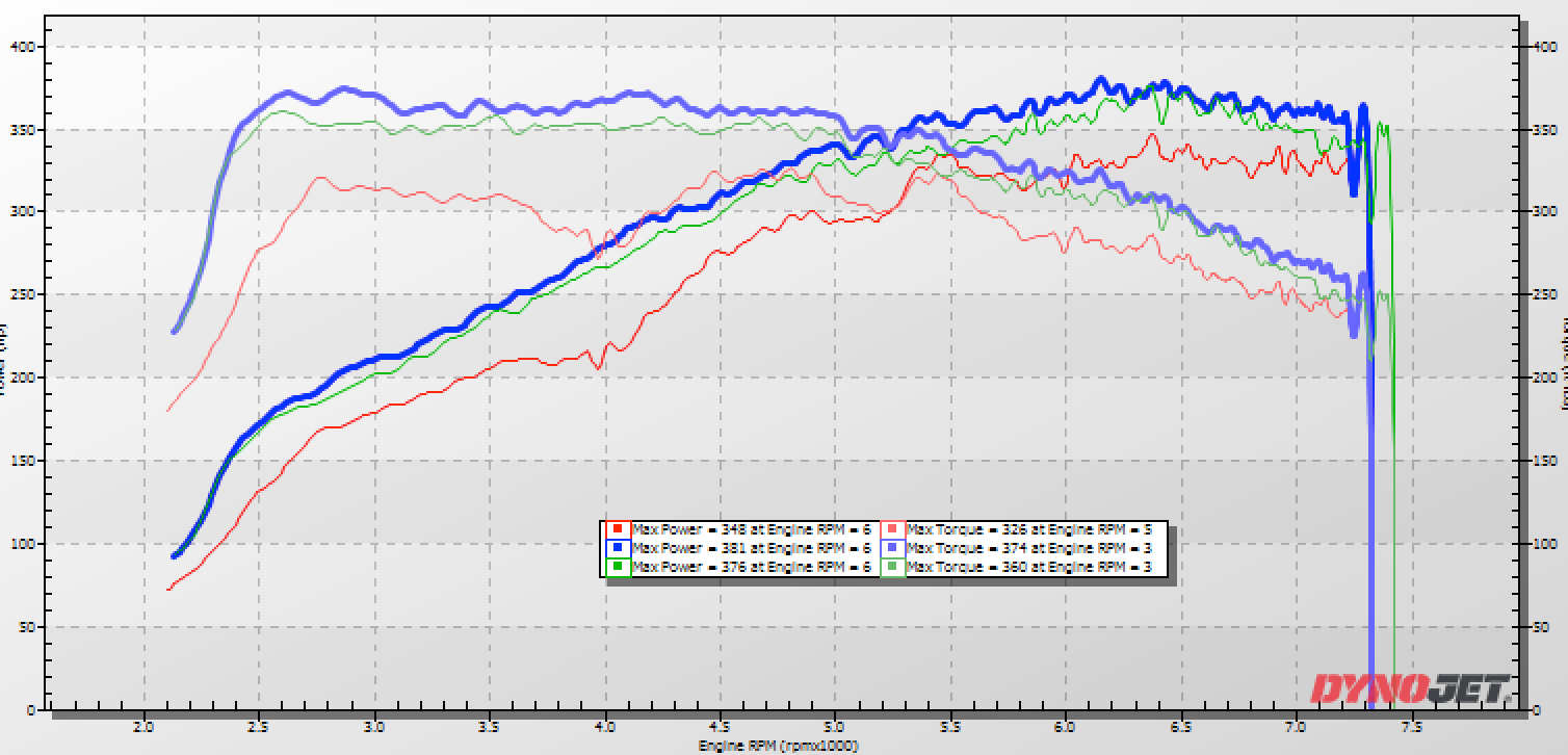
The Above chart outline some of the key differences in components between the 991.2 911 models. The drivetrain in the 3.0 liter cars is identical outside of increasingly larger turbochargers incrementing up from base to S and GTS.

Carrera In Blue
Carrera S In Green
Carrera GTS in Red
Looking at the differences shown above we can see how the differences impact power and torque across the different models. The difference in turbocharger size can easily be shown by plotting them all next to eachother.
Surface Differences in 718 Models
The latest generation of Porsche Cayman and Boxster are commonly refferred to as their chassis designation – 718. COBB supports the full range of 4 cylinder turbocharged 718s including the base 2.0 liter and the 2.5 liter cars in the “S” and “GTS” models. The 2.0 liter motor in the base car shares some core characteristics with the 3.0 liter Carrera 911s whereas the 2.5 liter motor is more similar to a 3.8 liter found in the 991.2 Turbo and Turbo S. For example, the base 2.0 liter motor uses a non-VTG actuated turbocharger and has variable lift on just the intake camshaft. In contrast the 2.5 liter motor in the S and GTS models uses a VTG based turbocharger as well as variable lift on both intake and exhaust camshafts and this is exactly the same configuration as the 3.8 liter 991.2 generation of 911.
Boxster S Stock
Boxster S
COBB Stage 1Tune 91 Octane
Boxster S
COBB Stage 1 93 Octane
Torque Control System
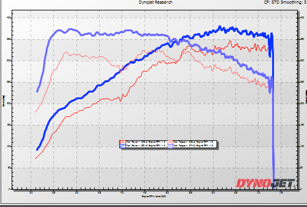
After selecting the most appropriate initial calibration, prepare to test and refine the calibration on a chassis dynamometer. When creating a custom tune, it is best to begin testing under low load conditions by lowering the target torque tables.
In these vehicles the relationship between these tables is very direct in terms of controlling the difference between the torque command and output. Here you can see that the shape of the torque curve as measured by a chassis dynamometer very closely mimics the run using that map (Shown in blue)
As mentioned earlier, all 991.2 (3.0 and 3.8 liter 911) and 718 (2.0 and 2.5 liter Cayman /Boxster) are controlled via a torque request dictated by accelerator pedal position. The requested torque tables are located in the “Torque Tables” folder. Comparing an OTS calibration with stock highlights main tables used to add and subtract torque and power. Within this folder there are actually very few meaningful tables that will need to be changed in the final calibration. Most of these tables represent torque limits of two types. The first type is an overall torque limits and the second type are those limits related to traction control and left foot braking, and therefore are moved out of the way (set to maximum values).
Overall Torque Limits
Actual gear for enabling torque limitation
Initialization torque for vehicle speed profile
Lower vehicle speed threshold for enabling torque limitation
Max engine torque depends on pedal value and brake pressure / brake torque limitation
Maximum Reference Indicated Torque
Minimum torque for vehicle speed-based torque limitation
Upper vehicle speed threshold for enabling torque limitation
Torque limit for TCU based on variant coding error
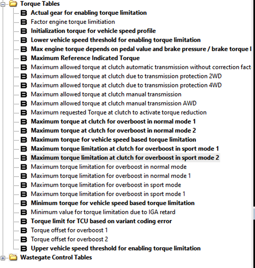
Just 4 tables are used to dictate increased or decreased torque and power in most 991.2 and 718 vehicles. These tables are the MAIN tables you can use to manipulate the power curve
Maximum torque at clutch for overboost in normal mode 1
Maximum torque at clutch for overboost in normal mode 2
Maximum torque limitation at clutch for overboost in sport mode 1
Maximum torque limitation at clutch for overboost in sport mode 2
These tables are separated into Normal and Sport mode. Normal and Sport mode are accessed by the driver through a selector on the steering wheel. COBB OTS maps have these modes set to the same values across all maps so the car makes the SAME power in Normal and Sport modes. However, it is entirely possible to set normal and sport modes to different power output. Some customers for example may want a low power tune for valet or use by an unskilled driver. While others may want separate street and track modes.
Normal and sport modes are separated into “1” and “2”. At this time differences are unknown and tables 1 and 2 should be set to the same values.
Torque Limits
Torque requests are not without an upper bounds. Finding and raising torque limits comprises a large component of successfully calibrating 718 and 991.2 vehicles.
Some torque limits are simple / static and are related simply setting an upper bound for torque. Many of these limits are simply moved out of the way in COBB OTS maps as previously mentioned in “Torque Request” above. Other torque limits are highly dynamic and related to current conditions. Conditions that will create a torque limit include.
Exhaust Gas Temperature (modeled)
Fuel limits (injection window, Fuel pump set points) (measured)
Detonation and Octane learning (calculated / measured)
Coolant Temperature (measured)
Oil temperature (measured)
Charge Air Temperature (measured)
Intake Air Temperature (measured)
Engine Compartment Temperature (modeled)
Turbo Rotational Speed (modeled)
Fuel Injection mode
Barometric Pressure (measured)
The vast majority of these static and dynamic torque limits are well out of the way for a stock turbo configuration supported by COBB OTS mapping. Details regarding each of these dynamic torque limiting scenarios are outlined in their respective specific subsystem folder below.
Simple / Static torque limits are contained within the “Torque Control” tuning folder. A few specific Torque limiting tables are here and worth describing.
Torque Limit – Intake air temperature.
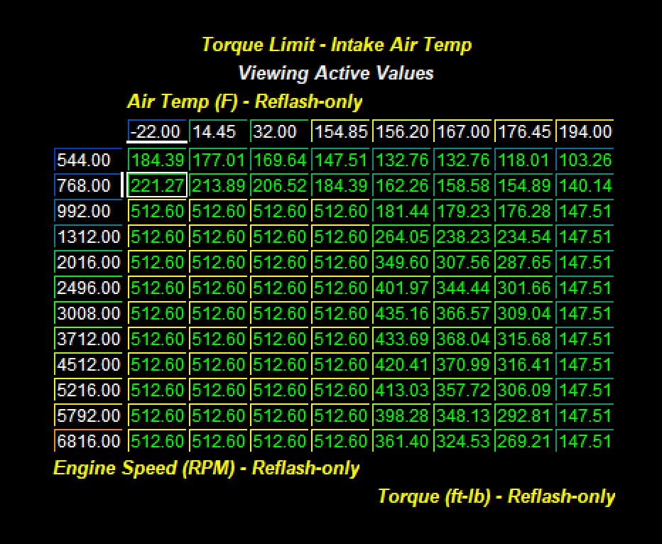
This table is tuned very conservatively from the factory and will serve as an active torque limit when the car is run repeatedly or driven under anything but perfect conditions. The Z data here isa torque limit and is defined by engine speed and Air Temperature. This is intake air temperature as measured at the manifold. It is not unusual for intake air temperature to be actively limited in a single dyno pull with these values set to factory. It is recommended to allow this function to limit torque but at slightly higher air temperature. This will make the car more consistent run to run.
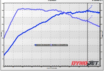
Intake Air Temperature Base Torque limit
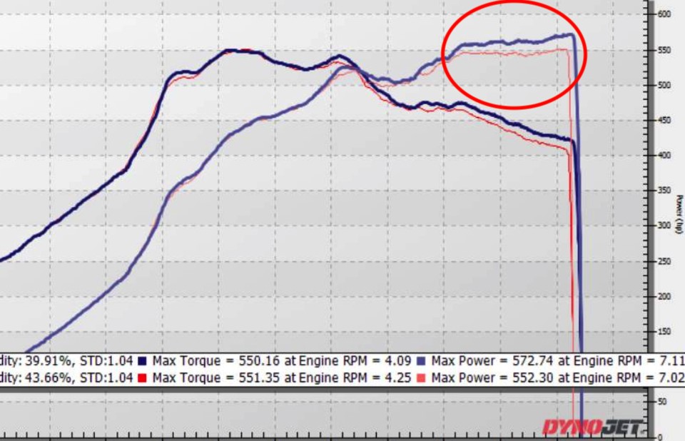
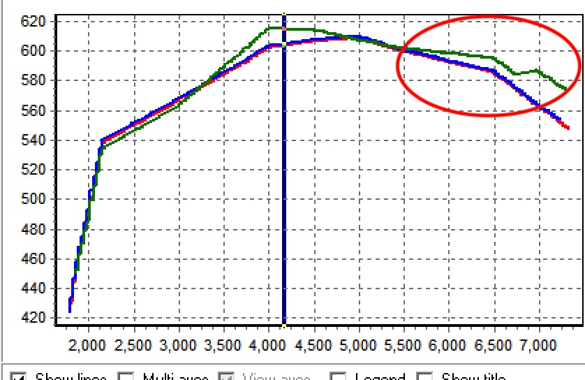
In this example (991.2 Carrera) you can see two power curves. The dyno plot shown in red was done with factory settings for the Air Temp based Torque limit. The Blue Dyno plot shows the results with the same car under the same conditions but with the Air Temp based torque limit increased to allow slightly higher temps before intervention. This can be observed in the second plot which graphs Engine Torque Limitation. The green line if the higher allowable torque generated by increasing allowable torque related to air temperature. This is just one example of a dynamically generated torque limit. In this case the limit was logically
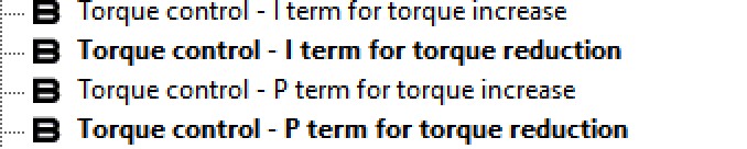
The maintenance of torque entering and exiting dynamic limiting conditions is controlled through a PID system. The I and P terms related to increased and decreased torque are held in Torque Control under the Torque Control PID subfolder.
Overboost Function
The factory ECU contains logic permitting “overboost”. This logic is turned ON and OFF with a simple 1 (on) or 0 (off). COBB OTS calibrations follow the OE calibration and DO NOT use this function. Use of this function creates a large torque request at lower RPM that is outside of ideal for these vehicles.
Torque request and offsets for overboost functions
The additional torque requested during overboost conditions is managed by a separate set of torque request tables within this folder.
Maximum torque limitation for overboost in normal mode
Maximum torque limitation for overboost in normal mode 1
Maximum torque limitation for overboost in sport mode
Maximum torque limitation for overboost in sport mode 1
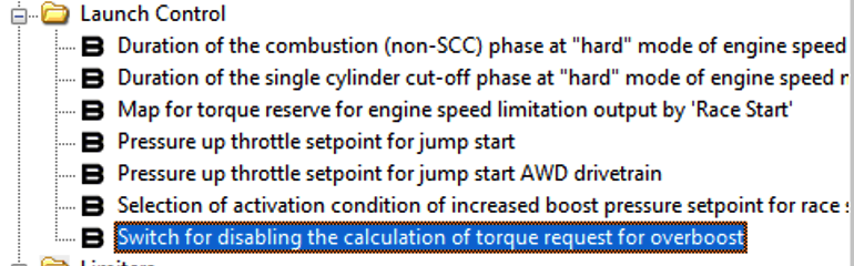
These torque requests are used as adder / limiter to standard torque request. In our experience these tables are ONLY utilized if the Switch for disabling the calculation of torque request for overboost is set to ON (1).
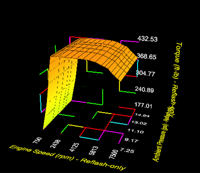
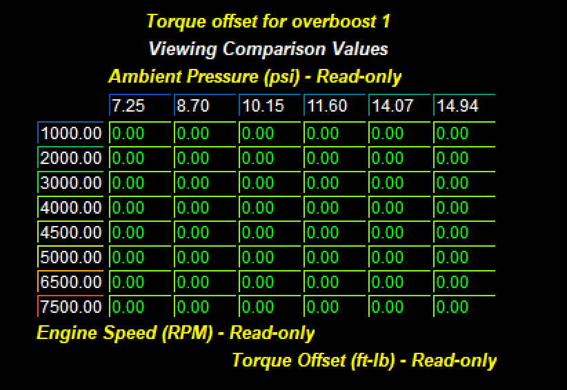
An alternate form of overboost is used conditionally in Sport mode. This additional torque is requested only in sport mode and only conditionally for a period of time. This additional requested torque is defined by ambient pressure and engine speed.
This particular conditional torque request increase is not utilized in 718 or 3.0 liter 911 but is used by 3.8 liter Turbo and Turbo S variants.
Torque offset for overboost 1
Torque offset for overboost 1
Torque Refence Setpoints
The torque control system in all 991.2 and 718 is calibrated around a set of internal standards that relate Torque to airflow and Airflow to Torque. Two sets of 64 tables serve to establish this relationship. The Torque reference tables are separated into 4 sets of 16 tables. The Z data for the table is reference torque and the axis are engine speed and airflow.
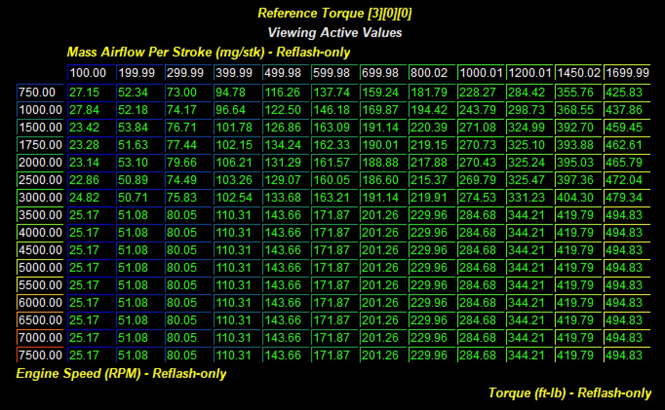
These tables are set up with three different paramters that denote different states for various active cam positions. This is represented by the three digits at the end of the name and are divided into three sections, with four possible values (0-3) for each position.
| 0 | 1 | 2 | 3 | |
|---|---|---|---|---|
| A Valve Lift State |
|
|
|
|
| B Intake Camshaft Advance | 0 Degrees | 20 Degrees | 40 Degrees | 50 Degrees |
| C Exhaust Camshaft Advance | 0 Degrees | 20 Degrees | 30 Degrees | 40 Degrees |
All setpoint values are weighted by the actual camshaft degrees. For example, intake cam degrees of 10 and exhaust cam degrees of 10 would interpolate 50% between intake cam index 0 and 1. Exhaust cam position is similarly weighted across index tables. Exhaust camshaft of 35 degrees would use a weighted value of 50% from index 2 and 50% from index 3.
For all 3.0 liter 991.2 Carrera and 2.0 liter 718 only the first 32 of these 64 tables is utilized because these cars do not have exhaust valve lift. (Index 1 is active for 0 and 1 only (all low lift and Intake low lift exhaust standard lift). In contrast, 2.5 liter 718 and 3.8 liter 991.2 variants ALL 64 tables are used as these cars have high and low lift intake AND exhaust as well as variable camshaft timing.
For stock turbo-based calibrations these reference tables can be left completely stock. These torque to airflow reference points are intrinsic to the vehicle performance. If these tables are extended or changed you MUST properly calibrate the Airflow Reference tables that are calibrated as the inverse of these tables - Airflow as Z data and Torque as X axis.
Boost Control
Torque Targets Generate Dynamic Manifold Pressure Set Points
The Porsche Siemens SDI21 uses torque control to influence how the car behaves on power and off power. This system uses input from a wide variety of internal variables and external sensors to dictate how the car reacts in certain conditions. The boost control system works in this same manner, not by trying to use a "standard" boost control setup, but by trying to achieve a target torque value. This is dynamic and varies based on conditions, temperatures etc.
This ECU uses various methods to control torque output, such as closing the throttle plate when the car overshoots a target torque table. Accordingly, you will always want to monitor throttle plate opening as it is a way for the car to lower the torque output. Other methods include lowering ignition timing, or changing air fuel ratios. So you want to be sure that the car is optimally calibrated in all conditions.
In a nutshell the car attempts to hit the requested torque by calculating how much load (and thus the amount of boost) the car will need to achieve in order to meet the torque request.
VTG vs Conventional Wastegate Turbo Control Systems
The 991.2 and 718 vehicles use two different types of turbochargers. The base 2.0 liter in the Cayman Boxster utilizes a turbocharger controlled by a standard wastegate. 991.2 3.0 liter cars use the same conventional wastegate system. In contrast, the 2.5 liter motor in the S and GTS 718 as well as the 3.8 liter Turbo and Turbo S control boost pressure through specialized variable geometry turbine housings called VTG – short for Variable Turbine Geometry.
At it's heart the VTG system use variable vanes inside of the turbocharger itself in order to adjust the velocity of flow through the turbine housing of the turbocharger. By bleeding off more of the pressure it's able to reduce how much boost pressure is created, and when more is needed it can redirect exhaust flow to capture as much output as possible. With the boost controlled by these vanes, there is no wastegate being used to bleed off extra pressure.
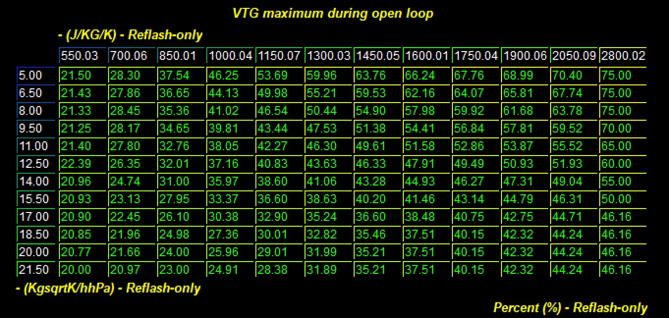
VTG based systems use a series of tables that function as feed forward and situational maximum wastegate duty. These tables represent VTG function as a number from 0 to 100 with 100% indicating maximal desired turbo speed (smallest AR, high back pressure) and 0 equal to the largest turbine AR and lower turbine energy (low back pressure).
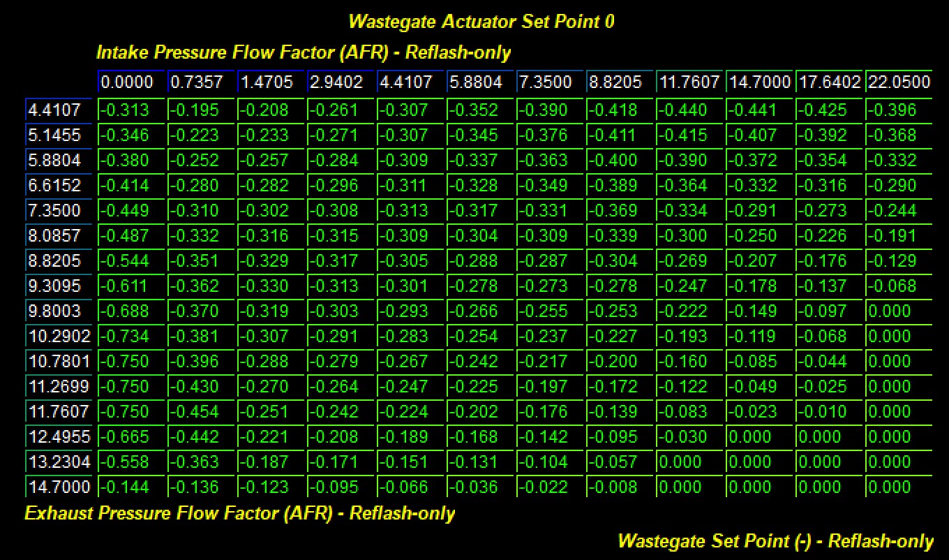
Conventional wastegate systems (2.0 liter 718 and 3.0 liter 991.2) utilize a series of tables to indicate wastegate position (0 = fully open wastegate / low boost, -1 = fully closed / full boost). This table is set up as a function of turbine flow and intake flow.
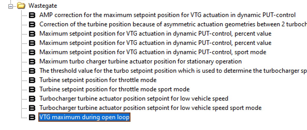
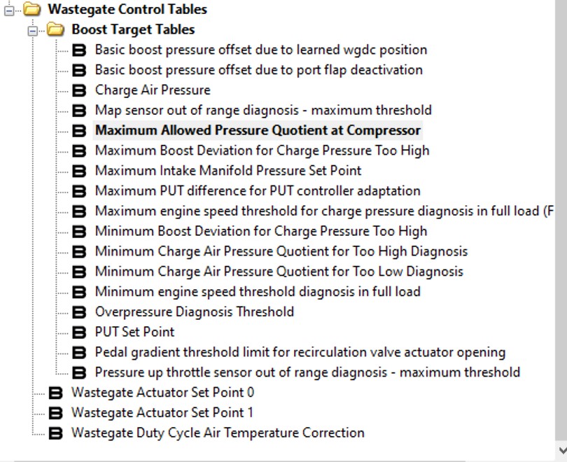
Because of the intrinsic link between torque request and desired manifold pressure there is very little to needed to change on the factory boost control settings. The car will make the boost needed to create the requested torque within the airflow limits. In fact, within the Wastegate Control Tables folder and the Boost Target Tables subfolder just a handful of tables are altered from stock.
Two other table related to boost control that are very useful. Torque target/load based turbo control systems are always somewhat difficult conceptually to calibrate with great confidence because there are not always clear ways to directly limit boost. For example, when intake air temperatures rise, boost pressure will also rise as the load based system flows more pressure to maintain Air Mass in the fast of reduced density. Without proper safeguards in place this can lead to very large boost pressure, detonation, poor shifting, and otherwise reduced performance. So with this mind, it’s a good idea to somehow limit boost pressure. We have found two tables present in factory logic – tables not utilized in factory calibrations - that can function to limit boost. Those are Maximum Allowed Pressure Quotient at Compressor, and Maximum Intake Manifold Pressure Set Point
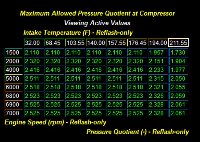
Maximum Allowed Pressure Quotient at Compressor
This particular table is functions to limit boost based upon air temperature and engine speed. The Z data in this table is compressor ratio. COBB OTS calibrations have been set such that this function limits boost if temperatures are extreme. The only downside to this table is that compressor ratio is not directly relatable to boost pressure as several other factors influence calculated compressor ratio. Stock data for this table is 16 bar (ie, its not used).
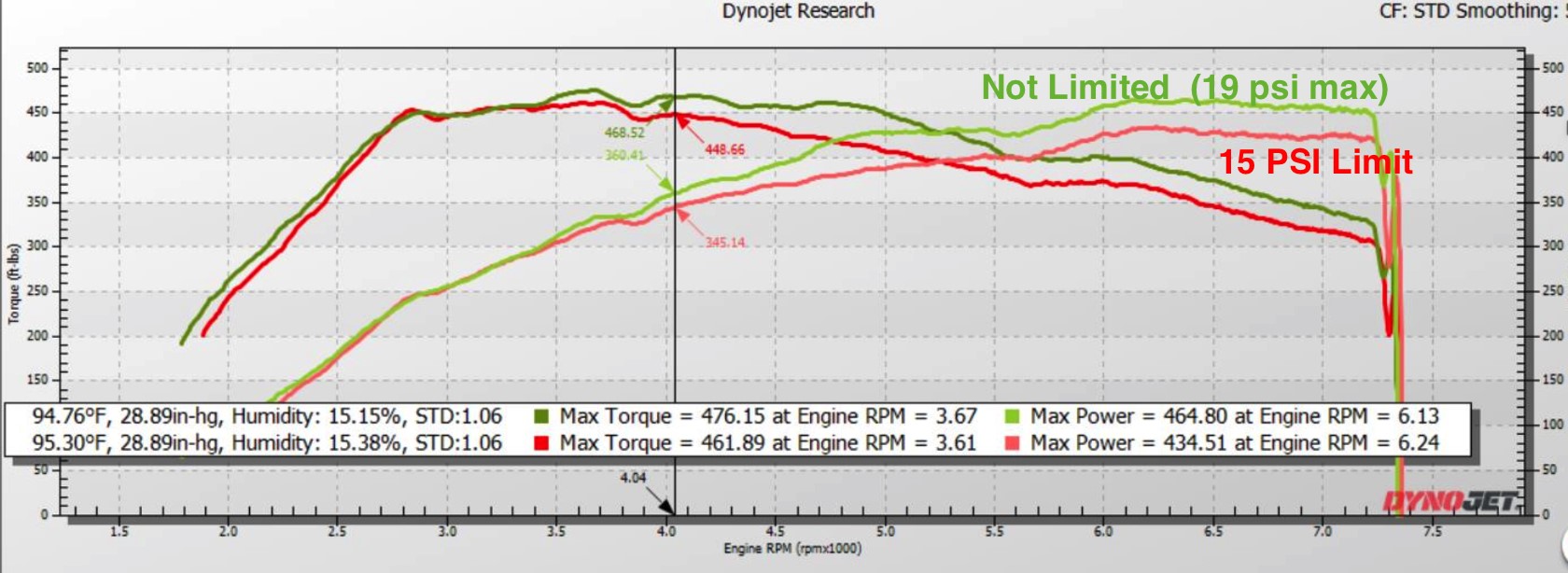
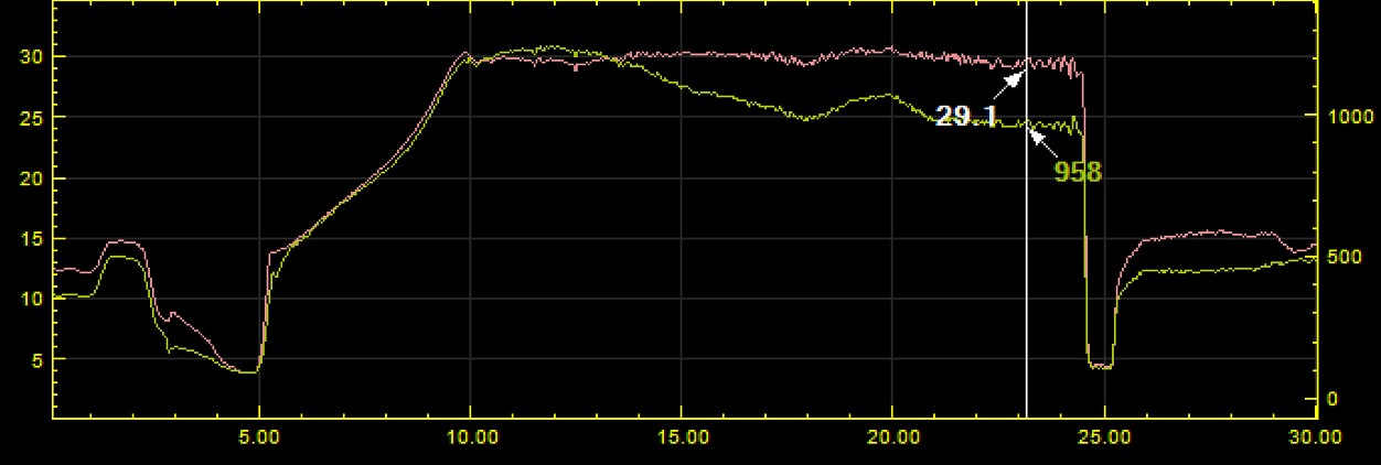
Maximum Intake Manifold Pressure Set Point
This table offers a more direct way to set a boost limit. It is a single value in absolute pressure and we have found that this 1D table value functions as a very effective upper limit to manifold pressure. The top shows a dyno plot of a Carrera S without a standard limiting manifold set point. (Green). Here the car makes 450 /450 and runs 15 and then up to 19 psi at higher RPM. When this same calibration is run with a 15 psi boost limit you can see the car runs less power and targets a perfect 29 psi MAP (lower graph corresponds to red above with MAP and Predicted Air Mass)
Airflow Limits and boost Control
Throttle and Torque Control
An important part of boost control and precise torque delivery is supported by throttle angle changes. Turbocharges are slow to respond to airflow change request. Turbochargers maintain far too much kinetic energy to rapidly and precisely change airflow. Throttle angle-based airflow changes are highly effective and as a result these rapid throttle changes are used as a normal means to regulate torque.
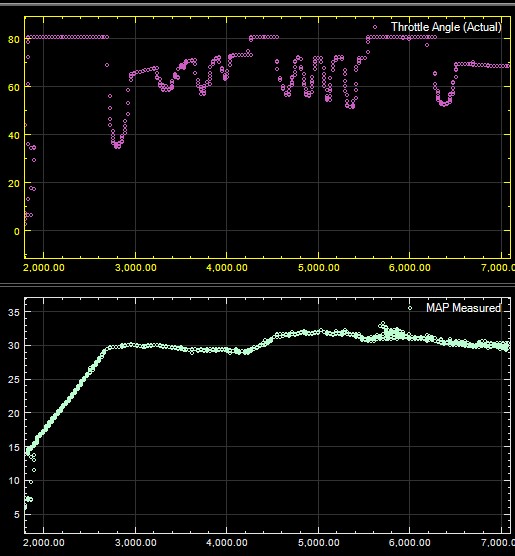
Below is a dyno graph of a Base Carrera. Data from this dyno pull show that the throttle (purple) is opening and closing throughout. Despite this, torque, HP and boost curves are arguably smooth and consistent. In fact, precise torque delivery is dependent upon this throttle based airflow control mechanism.
Airflow Limits
A critical part of the torque control strategy is aiflow limits. Boost targets are created with a torque request. Under most conditions there all these variables are well controlled. However, under some conditions such as high load PDK shifting, or higher temperatures, higher than desired boost pressures are likely. This behavior is logically limited by airflow limits through throttle closure and/or wasegate control.

The Z data for this table is Predicted Air Mass as measured in Airflow Per Stroke in mg. Predicted Air Mass is a log parameter. It is ideal to raise this table out of the way while calibrating until the desired torque curve is achieved and then reduce this table to values 20 to 50 mg/stroke higher than that achieved across the RPM range during a single full RPM high gear sweep.
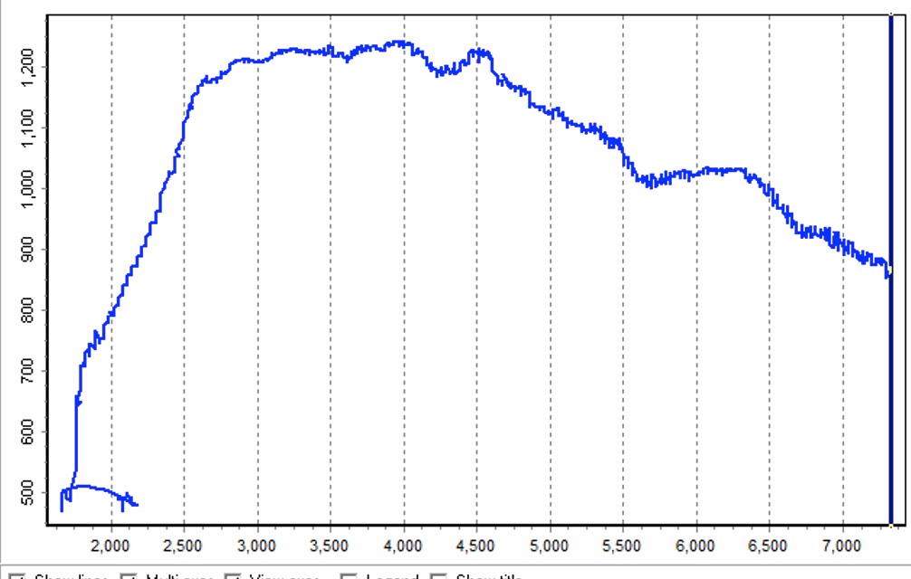
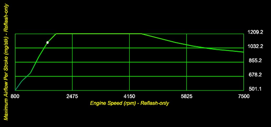
In the example above Predicted Air Mass (blue) peaks at ~1200 mg/stroke at lower RPM and then falls to around 900 at higher RPM. The corresponding Maximum available fresh air going into the cylinder at standard condition setting parallels this and prevents overboost at shift. DO NOT set this table to its maximum as a way to remove airflow limits. The car will overboost at shift and run poorly overall. Airflow create an RPM bases boost limit.
Reference Airflow and Airflow Setpoints
The torque control system in all 991.2 and 718 is calibrated around a set of internal standards that relate Torque to airflow and Airflow to Torque. Two sets of 64 tables serve to establish this relationship. The Airflow reference tables are separated into 4 sets of 16 tables. The Z data for the table is reference Airflow and the axis are engine speed and Torque.
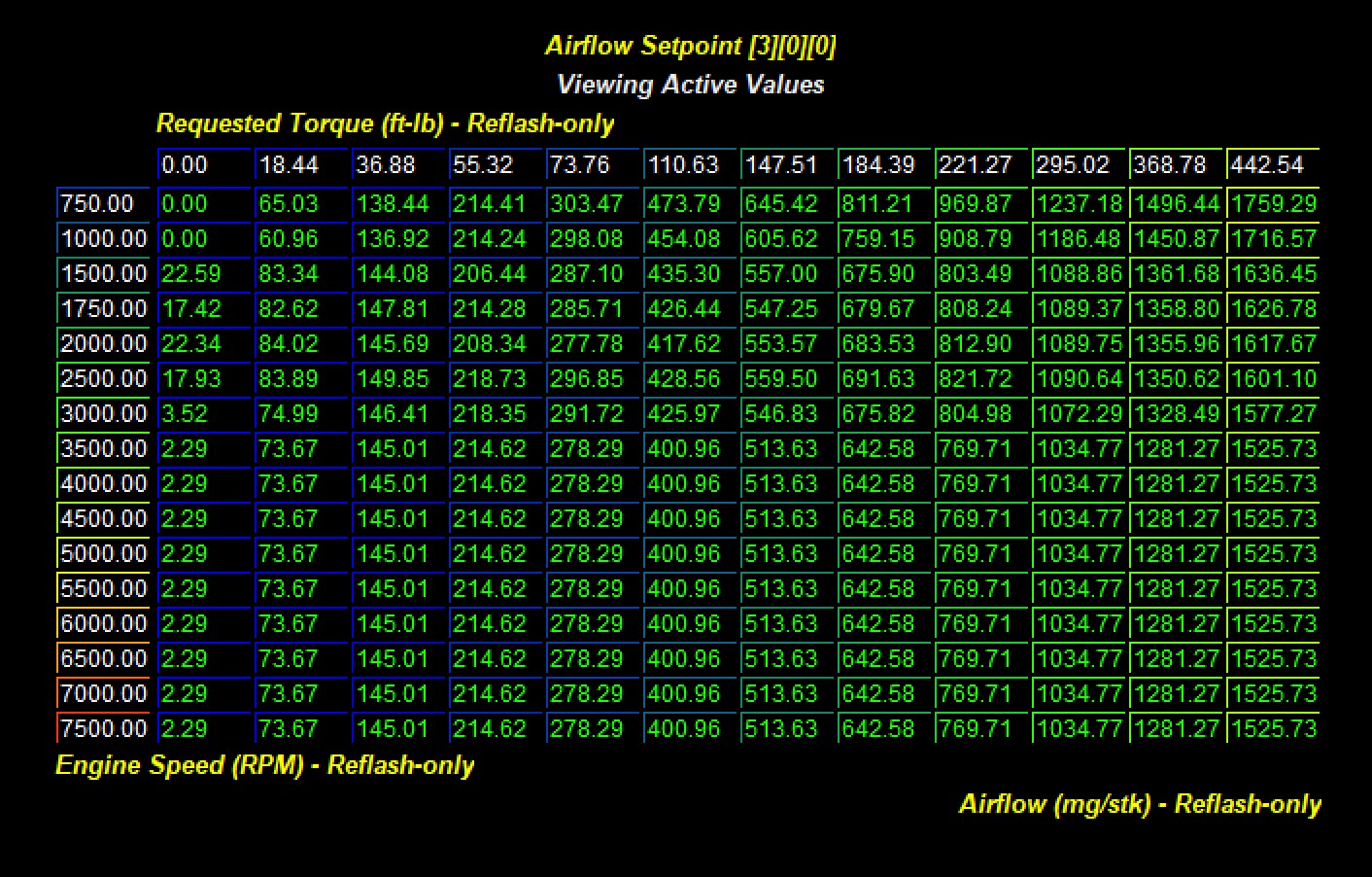
These tables are set up with three different paramters that denote different states for various active cam positions. This is represented by the three digits at the end of the name and are divided into three sections, with four possible values (0-3) for each position.
| 0 | 1 | 2 | 3 | |
|---|---|---|---|---|
| A Valve Lift State |
|
|
|
|
| B Intake Camshaft Advance | 0 Degrees | 20 Degrees | 40 Degrees | 50 Degrees |
| C Exhaust Camshaft Advance | 0 Degrees | 20 Degrees | 30 Degrees | 40 Degrees |
All setpoint values are weighted by the actual camshaft degrees. For example, intake cam degrees of 10 and exhaust cam degrees of 10 would interpolate 50% between intake cam index 0 and 1. Exhaust cam position is similarly weighted across index tables. Exhaust camshaft of 35 degrees would use a weighted value of 50% from index 2 and 50% from index 3.
For all 3.0 liter 991.2 Carrera and 2.0 liter 718 only the first 32 of these 64 tables is utilized because these cars do not have exhaust valve lift. (Index 1 is active for 0 and 1 only (all low lift and Intake low lift exhaust standard lift). In contrast, 2.5 liter 718 and 3.8 liter 991.2 variants ALL 64 tables are used as these cars have high and low lift intake AND exhaust as well as variable camshaft timing.
For stock turbo-based calibrations these reference tables can be left completely stock. These torque to airflow reference points are intrinsic to the vehicle performance. If these tables are extended or changed you MUST properly calibrate the Airflow Reference tables that are calibrated as the inverse of these tables - Airflow as Z data and Torque as X axis.
Tuning for appropriate Air to Fuel Ratios
Fuel system overview 991.2 Carrera and 718 use a direct injection fuel system with a low pressure lift pump and a high pressure direct drive pump. Fuel pressure is nearly 190 bar. The 991.2 has moved the fuel injectors from the side of the cylinder to the top which allows for a more efficient combustion event. These 7 hole injectors with a new location and higher pressure create a very efficient combustion event. So much more efficient in fact that Porsche was able to delete secondary air injection systems as start up emissions are extremely clean. All new for the 991.2 is a 7 hole fuel injector at the side of the combustion chamber with a more than 500 psi fuel pressure increase. This new fuel system is highly efficient. All 991.2 Carrera (base, S, and GTS) have exactly the same fuel system.
Fuel System limitations and associated torque limits
The fuel system on the 991.2 appears to have a large overhead and will likely support at least e30 ethanol concentrations. The fuel system in the 2.0 liter and 2.5 liter 718 is not as well understood and our early work with this system has shown that it struggles to keep up with even slight power increases on pump fuel. These limitation on pump fuel can be alleviated or reduced by opening up the injection window. If the injection window is too constrained or injection is happening during the combustion stroke, 718s get very “choppy” feeling AND they will hit a torque limit related to fuel delivery.
Within the Fuel Control folder there are at least two tables than help define the injection window.
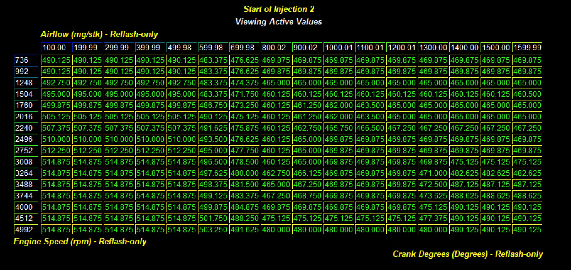
Start of Injection 1
Start of Injection 2
 \
\
These two tables indicate the start of injection in crank degrees and are defined as a function of airflow and engine speed. Increasing these values by 20 to 40 crank degrees in high load areas will increase fuel window and potentially decrease the possibility of hitting a fuel deliver based torque limit.
Late End of Injection Limit for Torque Limit Activation

It is also worth noting that some torque limits related to fuel delivery can be alleviated by choosing a leaner AF ratio. These cars can run very lean without issue. Most of the OTS calibration for 3.0 liter and 3.8 liter 991.2 target 12.5 to 12.2:1 AFR. This is conservative. Because fuel system related torque limits were an issue with 718 we increased injection window AND leaned the car out to 13:1 in problematic areas and generated enough fuel delievery room to eliminate the torque limit/reduction request.
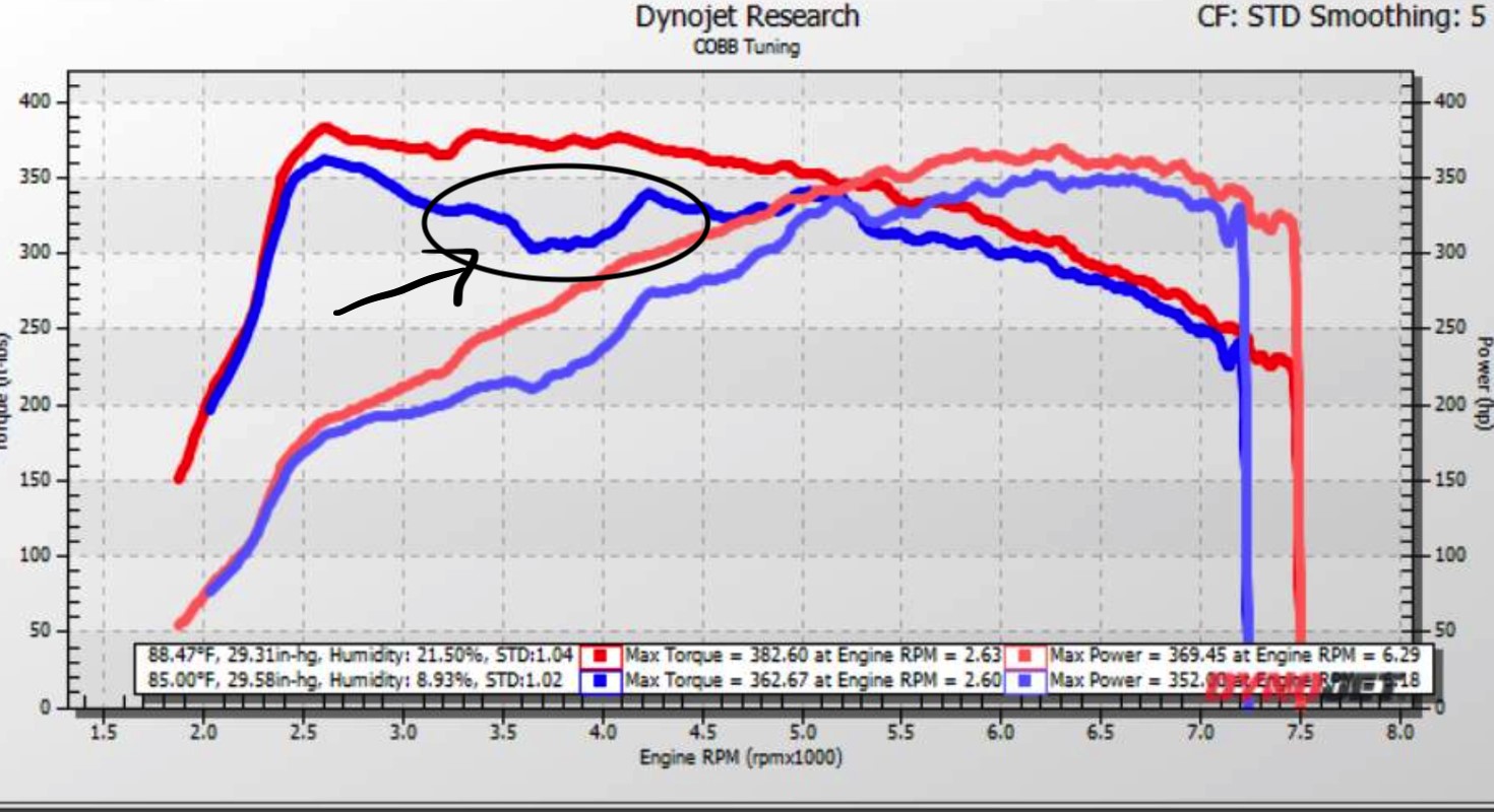
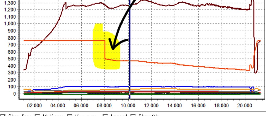
Fuel delivery based torque limits were an impediment to early OTS map delivery for 718. The upper graph shows a two power plots. You can see the blue graph has a major torque decrement that corresponded to a synchronized torque reduction request (lower graph). The SOI tables were used to increase injection window and this torque limit was eliminated and allowed a much smoother more consistent torque and power delivery with adequate fuel (Upper graph, Red Dyno Plot)
Closed Loop fuel control
Air to fuel ratios for these vehicles are directly impacted by several tables. The Porsche fuel control system operates in a closed loop control strategy. This means that the car runs a set of wideband air fuel sensors and is constantly adjusting the fuel targets based on a collection of variables.
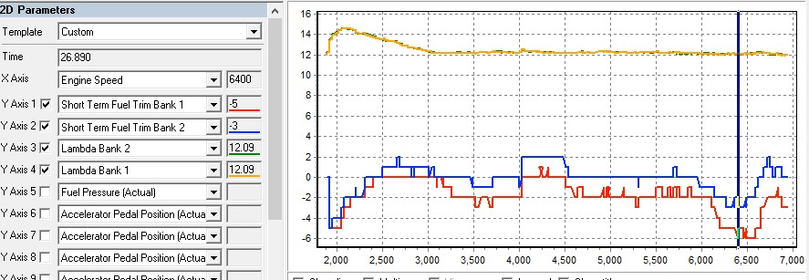
Closed Loop Fuel System Operation
Two separate banks represent the two sides of the motor. This graph shows gasoline AF ratio measured by separate internal wideband oxygen sensors on each bank (yellow and green). Small deviations from target are compensated through fast real time changes in fuel delivery as reported by Short Term fuel Trim (Bank 1 and 2, blue and red above)
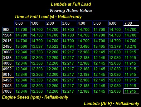
Closed Loop Targets Depend on Time at WOT
Within the Fuel Tables folder you can see that a variety of fuel tables have been modified. The Porsche factory calibration is extremely lean and only transitions to a more enriched air to fuel ratio under high load or in conditions that might damage catalysts.
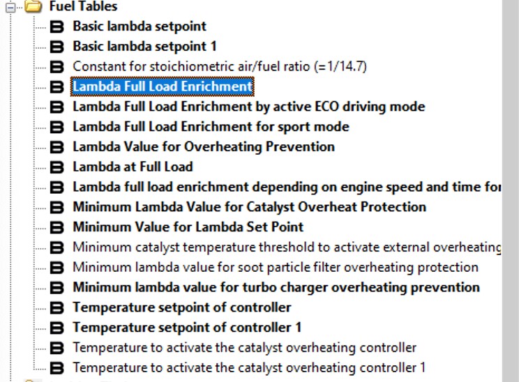
One of the more interesting ways that 991.2 Carrera regular full load fuel target is based upon time at wide open throttle. COBB OTS maps use this OE fuel control table to produce a slightly richer mixture for increasing time at WOT.
- Lambda at Full Load
- Lambda full load enrichment depending on engine speed and time for active ECO drive
- Lambda Full Load Enrichment for sport mode
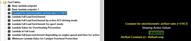
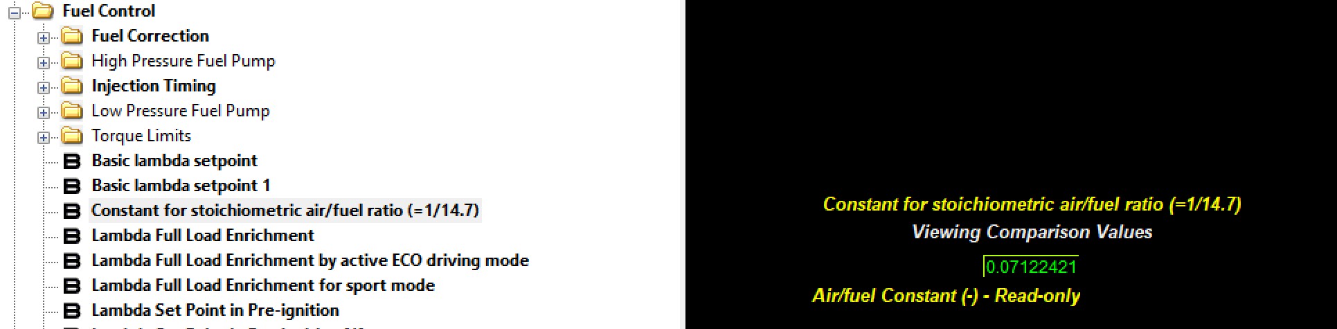
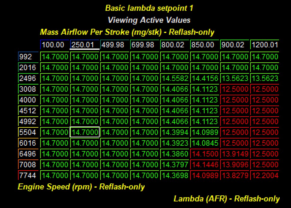
Stochiometric set points and ethanol based calibrations
The 991.2 fuel system is calibrated for a specific stochiometric set point using the Constant for stoichiometric air/fuel ratio. This ratio is the inverse of fuel stochiometric value of 1. For 10% ethanol pump fuel this value is 1/14.1or 0.071224. If you are using a higher ethanol content fuel of 30% this constant is = 1/13.56 or 0.07375. COBB has not tested ethanol fuels in these vehicles so the limits of fuel system or tolerance for high fuel volume demand ethanol fuels is not understood. However, this new fuel system, with pressures in excess of 3000 psi is the most capable of any Porsche DIT fuel system.
Ignition Timing
The ignition control strategy in the Porsche 991.2 Carrera is very dynamic and has many contributing variables to determine the overall ignition timing value. There are a total of 64 main ignition tables currently in software that are grouped into 4 folders of 16.
These tables are set up with three different paramters that denote different states for various active cam positions. This is represented by the three digits at the end of the name and are divided into three sections, with four possible values (0-3) for each position.
| 0 | 1 | 2 | 3 | |
|---|---|---|---|---|
| A Valve Lift State |
|
|
|
|
| B Intake Camshaft Advance | 0 Degrees | 20 Degrees | 40 Degrees | 50 Degrees |
| C Exhaust Camshaft Advance | 0 Degrees | 20 Degrees | 30 Degrees | 40 Degrees |
All setpoint values are weighted by the actual camshaft degrees. For example, intake cam degrees of 10 and exhaust cam degrees of 10 would interpolate 50% between intake cam index 0 and 1. Exhaust cam position is similarly weighted across index tables. Exhaust camshaft of 35 degrees would use a weighted value of 50% from index 2 and 50% from index 3.
For all 3.0 liter 991.2 Carrera and 2.0 liter 718 only the first 32 of these 64 tables is utilized because these cars do not have exhaust valve lift. (Index 1 is active for 0 and 1 only (all low lift and Intake low lift exhaust standard lift). In contrast, 2.5 liter 718 and 3.8 liter 991.2 variants ALL 64 tables are used as these cars have high and low lift intake AND exhaust as well as variable camshaft timing.
For stock turbo-based calibrations these reference tables can be left completely stock. These torque to airflow reference points are intrinsic to the vehicle performance. If these tables are extended or changed you MUST properly calibrate the Airflow Reference tables that are calibrated as the inverse of these tables - Airflow as Z data and Torque as X axis.
Reference Ignition
The reference ignition tables represent the car running at the ideal timing for the engine and is the timing at which the reference torque levels are assumed to exist. Under most conditions these tables will not need to be touched.
Knock Control System
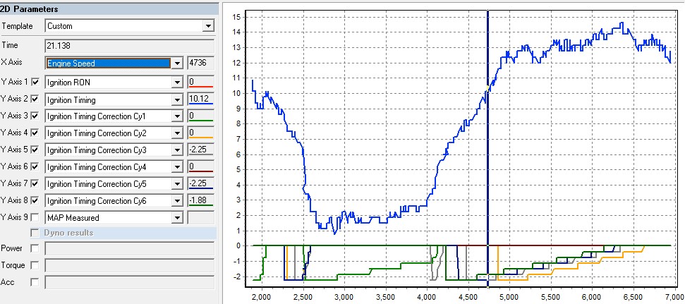
The knock control strategy on the Porsche 991.2 Carrera is very complicated and uses individual cylinder knock control to make changes to the ignition timing at all times. The system is very sensitive and thus almost always has some sort of feedback. You can monitor knock retard and ignition correction in each cylinder. This is the best way to check for detonation, and to ensure a safe running vehicle. The closer to 0 the better, but if it sways into the negatives (-2 and below) this is the car registering detonation. Since the car is very dynamic it is made to be sensitive. If you are getting values past -6 you will want to try and lower ignition timing, or add more fuel to try and see if you can bring the values back closer to 0. Running a race fuel will also help in getting the knock control values closer to zero.
Porsche individual cylinder Knock feedback systems. Ignition timing is adjusted per cylinder in response to engine noise consistent with detonation. This graph presents overall ignition timing (blue) and individual cylinder ignition adjustments (decrementing negative values) during a full load pull from 2000 RPM to redline.
Adaptive Ignition Timing and Octane Learning
The ignition control systems in 991.2 and 718 utilize a mechanism to learn fuel octane and adapt overall ignition strategy. This is a first for Porsche 911 as all earlier cars responded to fuel quality with highly sensitive ignition on an immediate basis but did not store this information in as a means predict fuel quality. 991.2 remember fuel quality through a not yet fully understood mechanism that translates immediate knock responses into an octane learning in the form of a number from 0 to 1 – Ignition RON. Ignition RON is used to calculate ignition timing offsets and, in extreme cases, reduce requested torque. In the OE calibrations this value is not reset. This means that a bad tank of fuel will be remembered ever after the fuel quality is increased. The core parts of this system remain intact within COBB OTS calibrations (ignition adjustments and the potential to reduce requested torque). COBB OTS maps however utilize factory logic to RESET the learned “Ignition RON” through each key cycle. This factory logic is located in Ignition RON reset. A value of “1” enables the key cycle reset while “0” maintains this learned octane value through key cycles. You can determine if the ignition RON has changed as this is a log parameter. 0 is high octane. 1 is low.
The adaptive octane learning uses two thresholds to determine whether to move RON value, to determine the direction of the move (toward 1 or 0) Max ignition for RON adjustment is the threshold for an increase in RON if ignition corrections is above this value. Minimum ignition for RON adjustment – if ignition correction is lower than this threshold the learned RON value will move toward 0 (higher octane). This means that the ECU is self-tuning to keep ignition correction between these Minimum and Maximum values.
The learned octane (RON value impacts overall ignition timing through a second table Table for ignition angle correction due to global adaptive circuit.
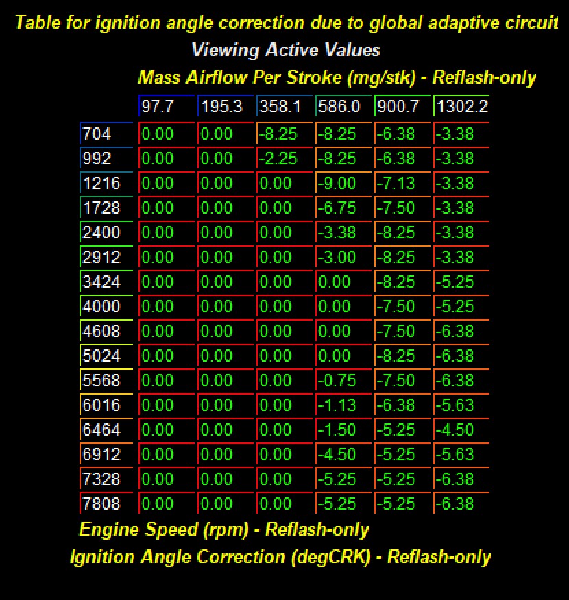
Learned Octane based Ignition reduction = (RON, 0 to 1) x (Ign Angle correction due to global adaptive circuit)
So, with a RON value of 0 (high octane), this global timing reduction is without impact. If ignition correction is more than Max ignition for RON adjustment then the RON will move from 0 toward 1. Any movement away from 0 will produce a timing reduction with 1 producing the largest timing reductions at high airflow. This background octane learning system does not reduce instantaneous ignition corrections. In fact, this system depends upon knock responsiveness in order to learn fuel quality.
This system not only impacts timing adjustment but also can decrement power as ignition corrections indicate lower fuel quality. It’s a logical system that in the absence of acceptable fuel, turns down the power to protect the motor.
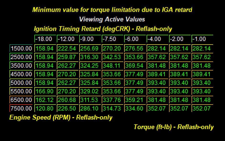
The magnitude of this adaptive system is indicated by the a table in the Torque Control folder called Minimum Value For Torque Limitation due to IGA retard
Minimum value for torque limitation due to Ignition Correction - Requested torque values above these thresholds will be limited as a function of knock correction. The higher the observed knock correction, the lower the allowable torque before limits are applied. IE, under conditions of high knock, torque will be limited
Knock detection Sensitivity If running built engines, you can change the knock detection thresholds in the software. By raising these tables, you are de-sensitizing the knock control system. THIS SHOULD BE DONE WITH GREAT CARE AS DOING THIS CAN RESULT IN ENGINE DAMAGE AS KNOCK CONTROL BECOMES LESS ACTIVE!!
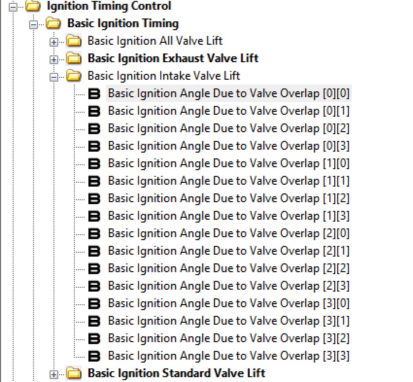
Ignition TIming Control Beyond Factory Strategy: Combustion Mode Timing Offset
One common challenge in newer Porsche calibration is ignition timing control. Starting with the 991.2 generation of vehicles ignition timing became much more complex. Each vehicle is mapped with 64 total tables grouped in 4 folders of 16 tables. These tables are segregated by valve lift.
- All lift (both intake and exhaust valves are high lift)
- Exhaust lift (only the exhaust is high lift)
- Intake lift (only the intake is in high lift)
- Standard lift (both intake and exhaust are low lift)
Within each of these groups of 16 the timing tables are further divided by their intake and exhaust cam position. The final ignition timing is calculated as a weighted blend of more than one table as cam position is not exactly that indicated by the index.
Ignition timing depending airflow and engine speed. References by valve lift, Intake cam position, and Exhaust cam position. [Index 1 is intake cam advance] 0 = 0, 1 = 20, 2 = 40, and 3 = 50 degrees. [Index 2 = exhaust cam position] 0 = 0 degrees, 1 = 20, 2 = 30 and 3 = 40 degrees. All ignition values are weighted by the actual camshaft degrees. For example, intake cam degrees of 10 and exhaust cam degrees of 10 would interpolate 50% between intake cam index 0 and 1. Exhaust cam position is similarly weighted across index tables. Exhaust camshaft of 35 degrees would use a weighted value of 50% from index 2 and 50% from index 3. See tuning guide for further description.
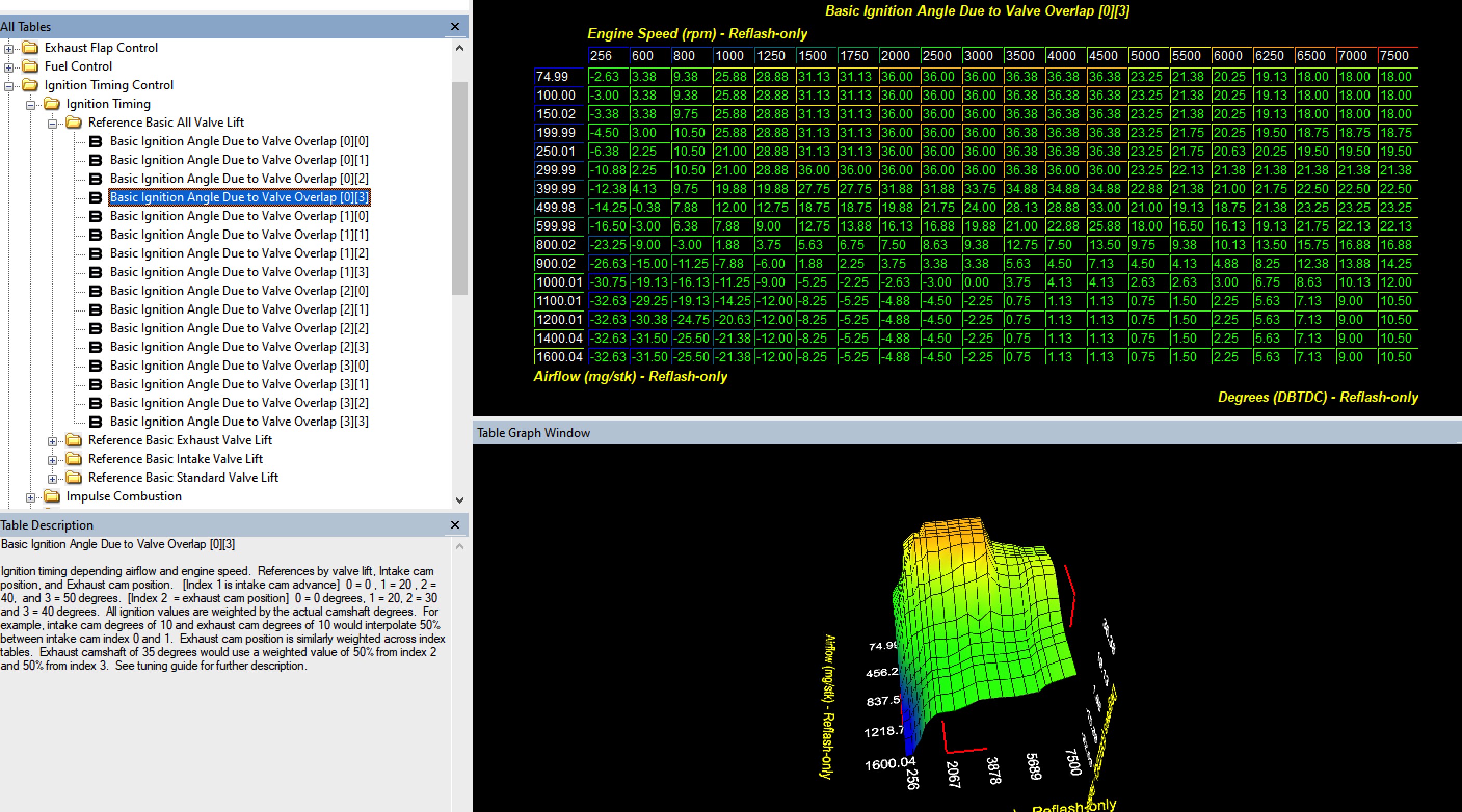
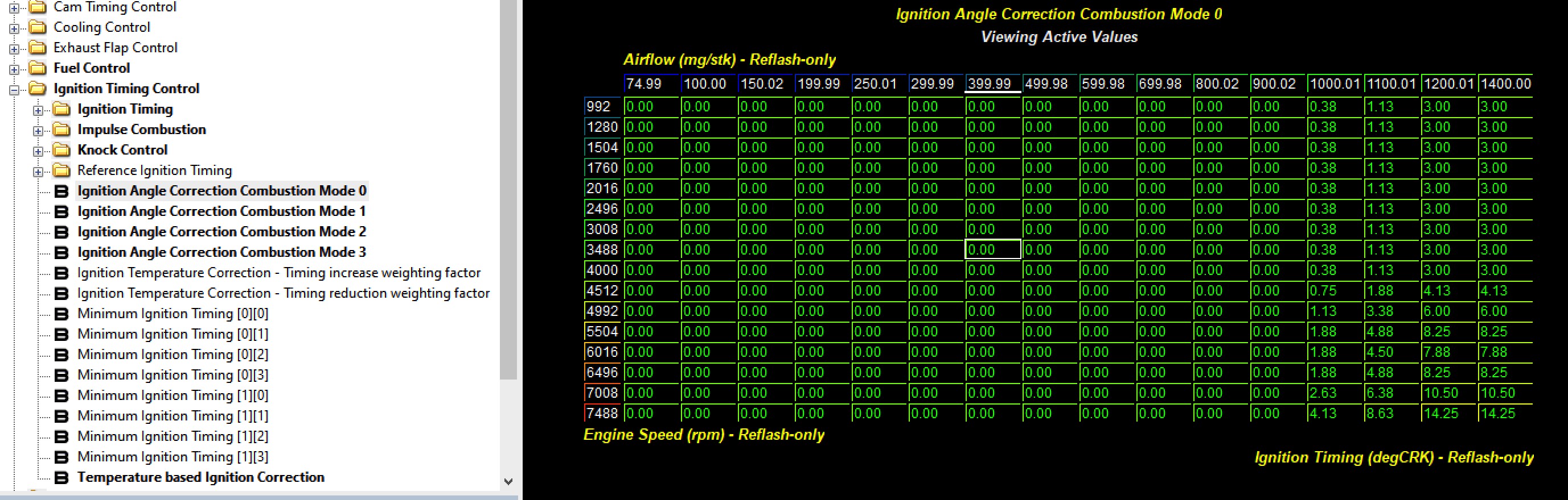
One of the 64 timing tables used to calibrate ignition timing on a 991.2 or 718. Timing control represents a challenge as it is difficult to know exactly which timing table is being utilized
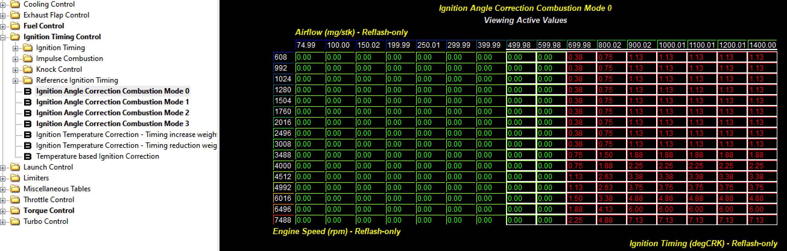
One way to get around this difficulty is to allow the factory to do most of the timing calculations and then use the “Ignition Angle Correction Combustion Mode 0-3” These tables are defined by RPM and airflow and have a huge amount of granularity as you can see. These tables are NOT used from the factory and are populated with “0”. However, careful application of timing (both positive and negative numbers can be used here) is an excellent way of managing FINAL timing output.
Here you can see a dyno plot from a 991.2 GTS with a turbo upgrade. Without using these timing control strategies and using the stock system the car makes 45 fewer WHP and the power is very “choppy” as you would expect on an under-timed engine (RED). When timing is added with the combustion mode tables, the power is smooth and substantive. This car was tuned with 100 octane unleaded fuel and was still well below MBT using this approach. 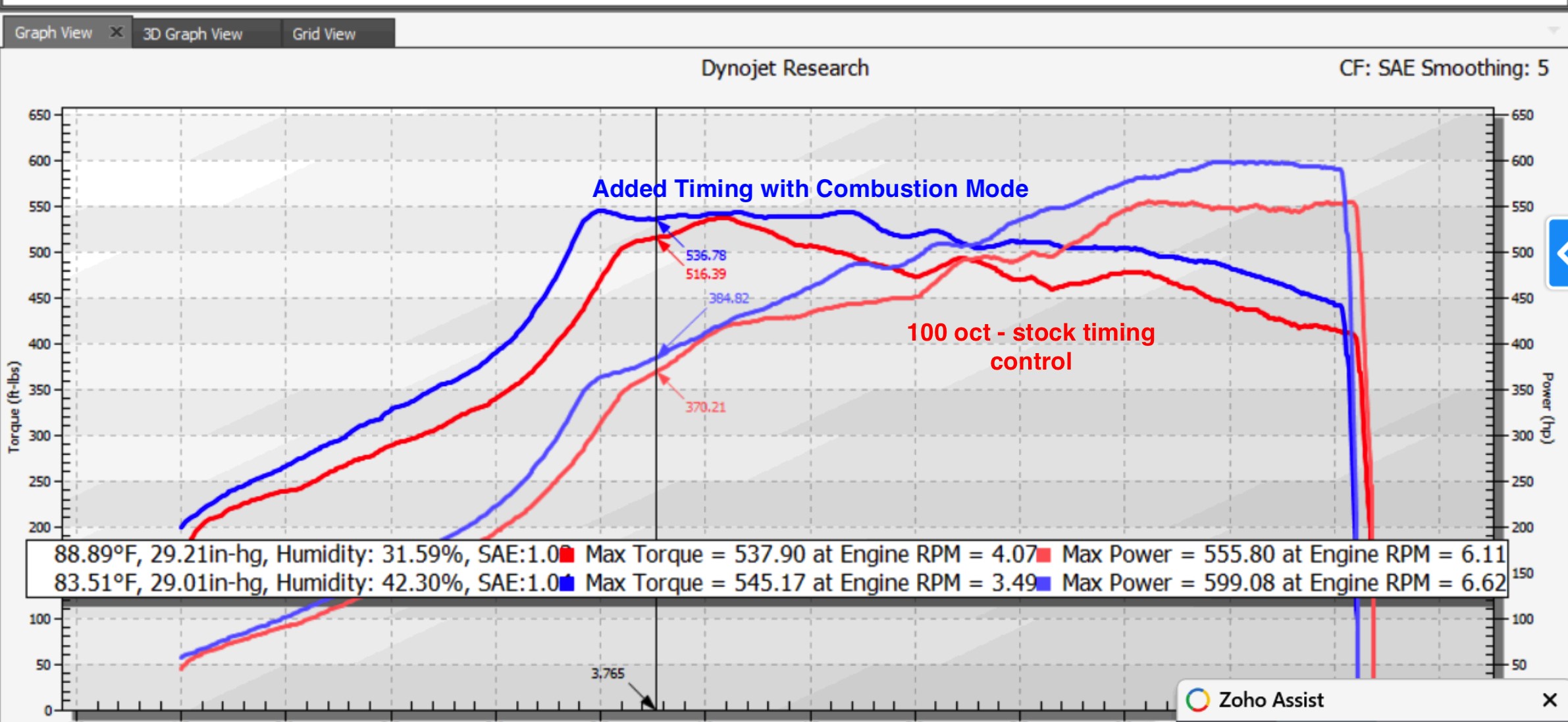
Methanol Injection Use
Fuel Control and Final Delivery (Methanol)
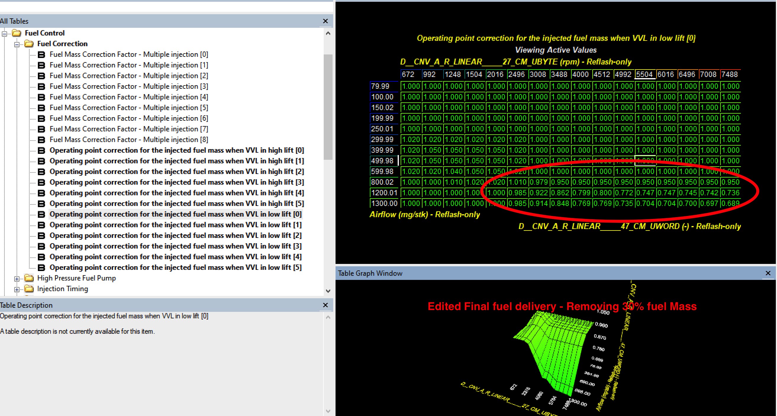
All modern Porsche utilize a closed loop fuel control strategy. An intrinsic VE system is used to model the fuel required given a specific airflow. Usually this intrinsic VE system produces accurate closed loop fuel control with very little correction (+/- 5%). However, modifications that change VE create inaccuracies in this system. Another way that fuel calculations are skewed is through the introduction of additional fuel via methanol injection or similar.
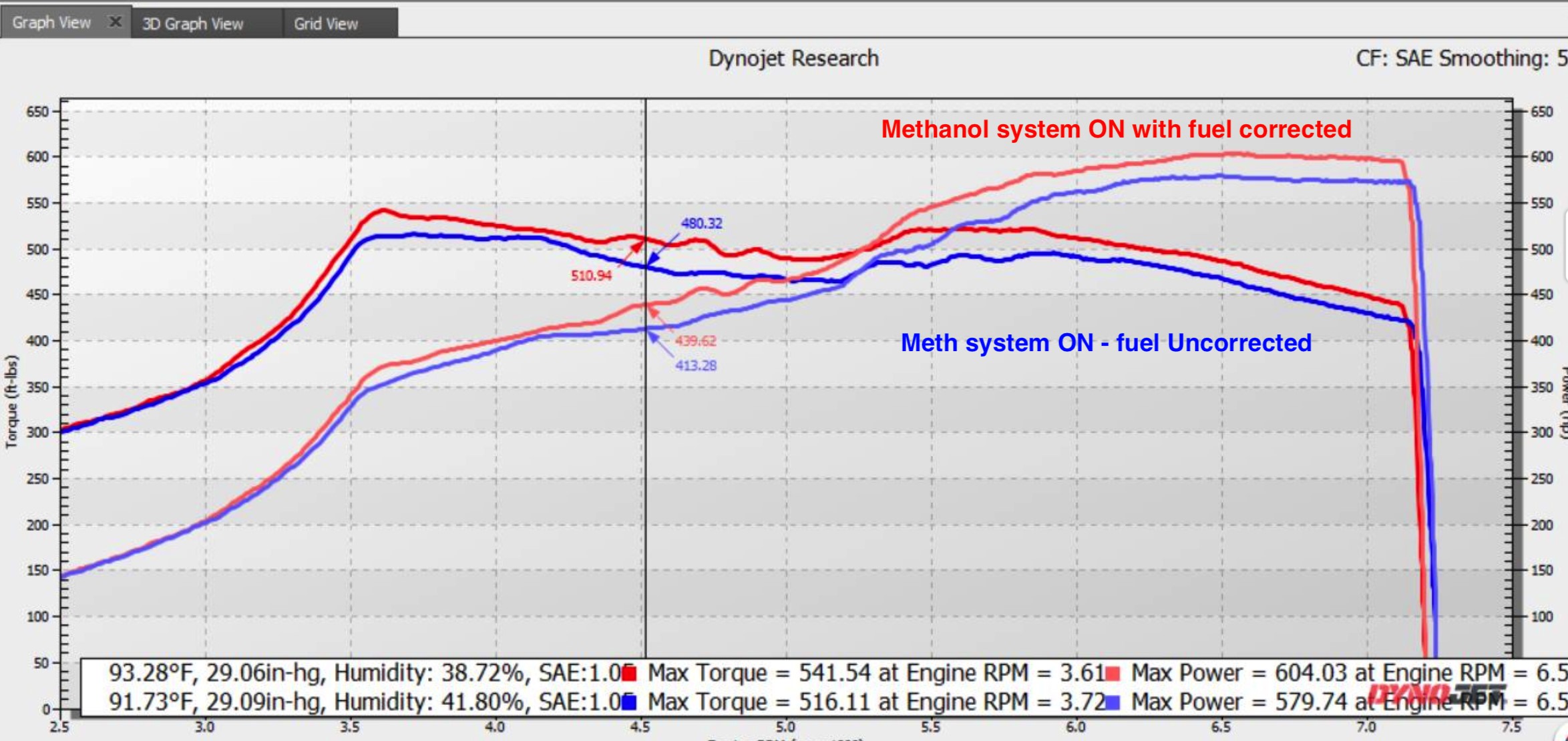
Fortunately there are several fuel correction tables that allow fuel mass to be added or subtracted as a function of Airflow and engine speed. These tables are highly granular which allows for a precise management of final fuel delivery. The fuel corrections created in the graph above used these correction tables to remove as much as 30% of fuel mass at high airflow and high RPM.
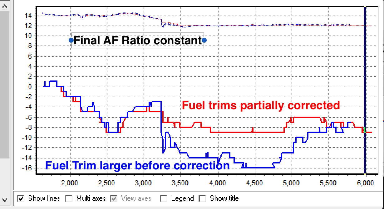
991.2 GTS equipped with a larger turbo. This power graph compares pump fuel with methanol injection active before (blue) and after appropriate fuel corrections and timing addition. Fuel corrections and proper ignition timing allow much smoother power and bring fuel trims within a more narrow window.
Ethanol Use
Fuel Control and Delivery (Ethanol)
(As tested up to 50%)
All modern Porsche utilize a closed loop fuel control strategy. An intrinsic VE system is used to model the fuel required given a specific airflow. Usually this intrinsic VE system produces accurate closed loop fuel control with very little correction (+/- 5%). However, modifications that change VE create inaccuracies in this system. This system is set up for use with low ethanol pump fuel which has a stoichiometric Air to fuel mass of 14.7:1. Pure ethanol, by contrast, has requires a much higher fuel mass of 9:1. This means that if pure pump fuel requirement is 1.0 unit mass for a given scenario pure ethanol would require ~1.6 mass units of fuel.
Within reason the Porsche closed loop fuel system can respond to minor +/- 10% changes in ethanol content. However, larger changes must be programed into the fuel setpoint for the vehicle. This fuel stoichiometry setpoint is a ratio of 1/(1 lambda fuel stoichiometry).
Below is a chart showing the relationship of ethanol %, stoichiometric AF ratio, and “Constant for stoichiometric air/fuel ratio (1/14.7)”.
| Ethanol% | Soichiometric Ratio | Constant for Stoichiometric AF Ratio |
|---|---|---|
0 | 14.7 | 0.068027211 |
10 | 14.13 | 0.070771408 |
20 | 13.56 | 0.073746313 |
30 | 12.99 | 0.076982294 |
40 | 12.42 | 0.080515298 |
50 | 11.85 | 0.084388186 |
60 | 11.28 | 0.088652482 |
70 | 10.71 | 0.093370682 |
80 | 10.14 | 0.098619329 |
90 | 9.57 | 0.104493208 |
| 100 | 9 | 0.111111111 |
The practical impact of changing the “Constant for stoichiometric air/fuel ratio (1/14.7)” is that the car recalculates needed fuel mass. This allows the closed loop fuel control to adjust for smaller changes.
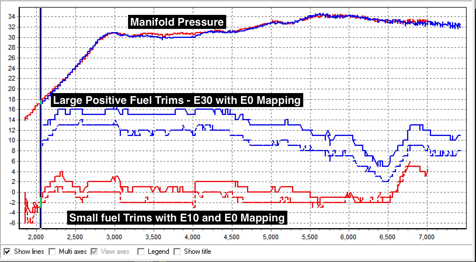
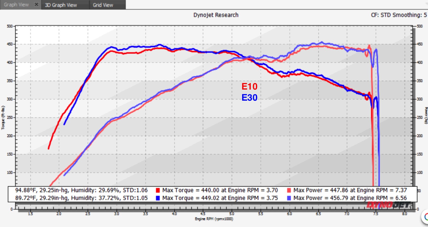
When using E30 in a Carrera S set up for E10 (pump fuel). You can see that the fuel trims are shift toward positive (more fuel volume). Here the vehicle is correcting injected fuel mass with active closed loop feedback. Despite a lack of proper Stoichiometric Set Point the resulting lambda is identical and power is similar with identical boost pressure.
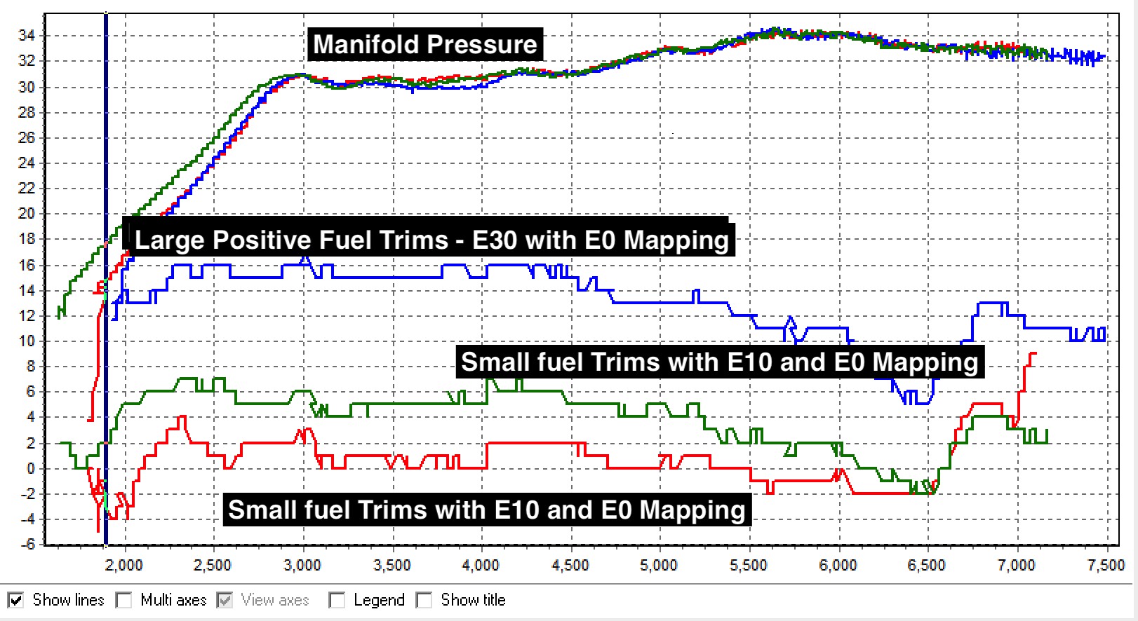

Running the car with the proper E30 Stoichiometric Constant produced better overall fuel trims (closer to 0) while power stayed similar. (Green)
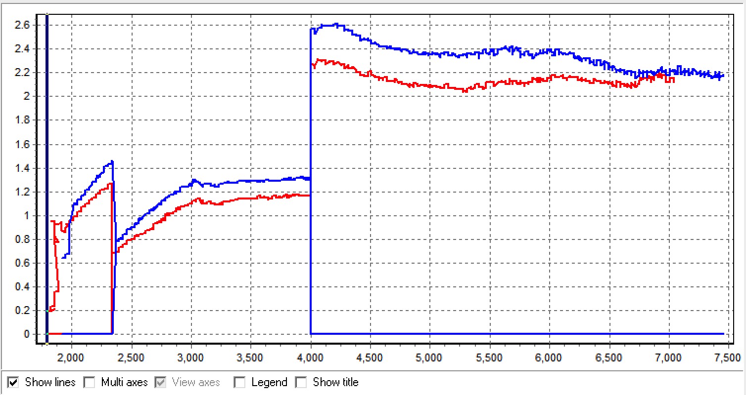
Because ethanol requires MUCH more fuel volume there might be torque limitations through fuel system limits. The graph below shows the difference in injection open time (the first part is doubled because of heterogeneous injection). E30 requires much longer injection time (blue)
To avoid running into fuel system based torque limits there are two basic approaches.
Run a Leaner Lambda Target
With a slightly leaner fuel target you'll reduce the amount of fuel being demanded at a given point by the fuel system.
Increase Injection Window
Advancing the SOI (Start of Injection) tables at higher load and RPM. Here the upper RPM and SOI is increased 3-5%. This tweak kept a fuel based torque limit from being hit and produced a smoother power curve.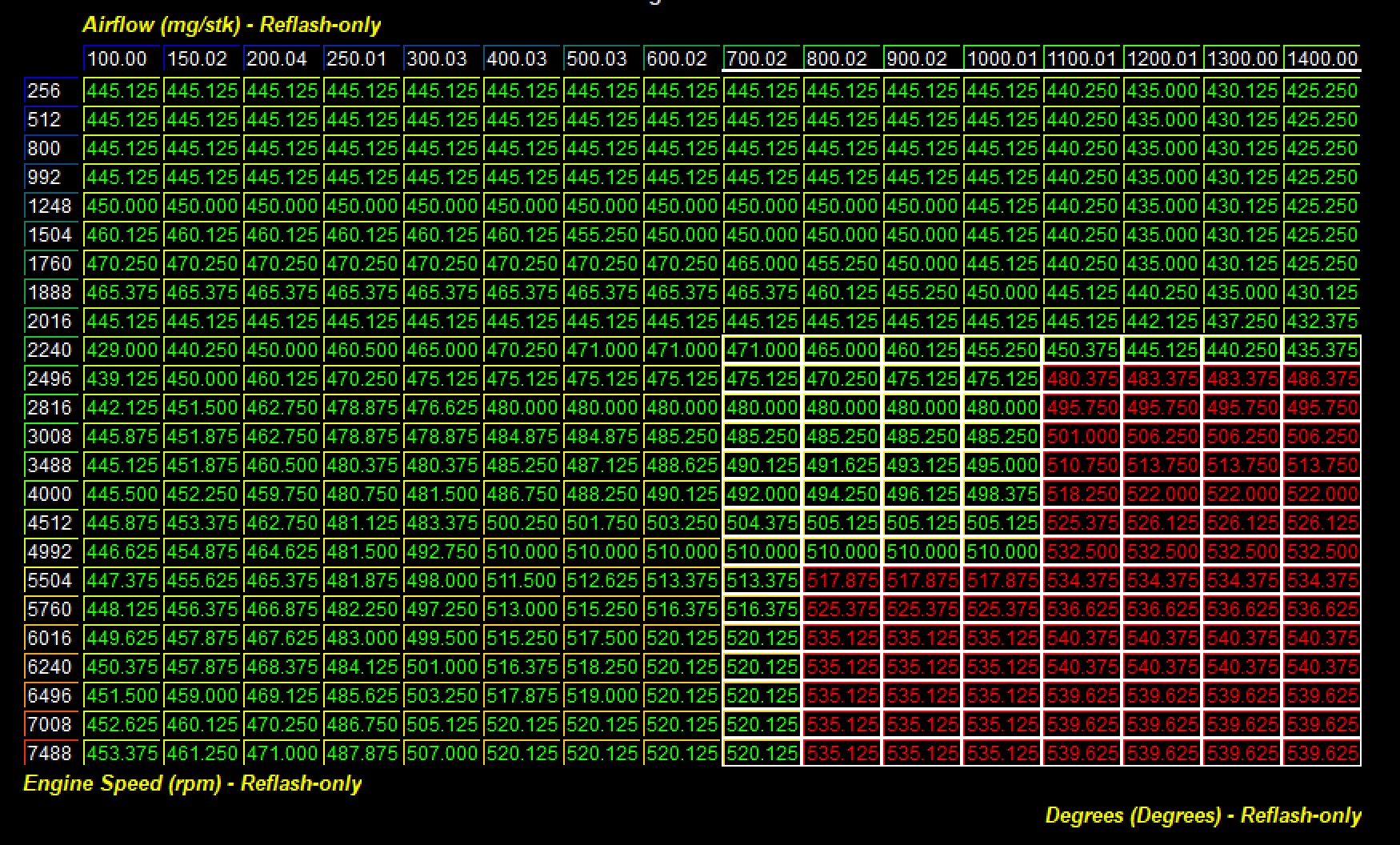
Ignition Control With Ethanol
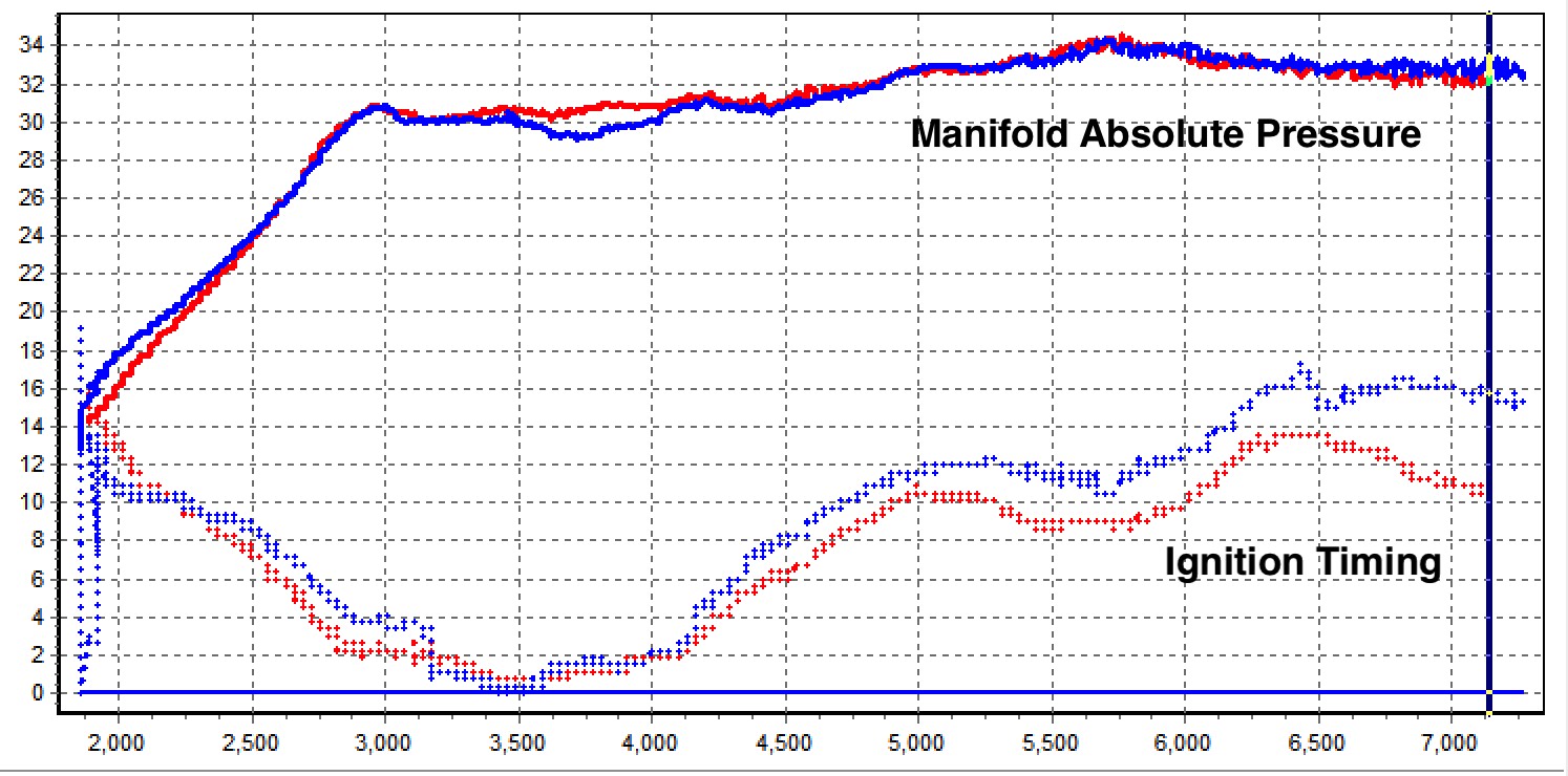
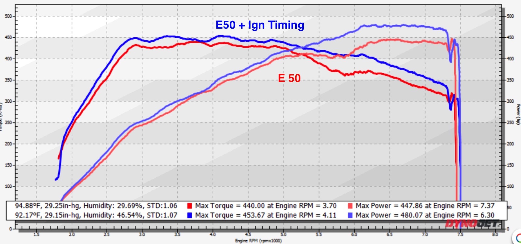
The last facet of tuning with ethanol is that stock or pump fuel appropriate ignition timing will be well below MBT when using ethanol. Timing changes can be made in the primary tables (all 32) but here I’ve used the same approach as with methanol tuning above and used the combustion mode timing offset tables to add timing as needed to this particular tune.
Here you can see that timing changes produces a very substantive increase in power! Ethanol fuels are amazing. This graph below is E50 run without timing changes and again after timing changes.
Precautions
Boost – The stock turbo chargers can produce boost levels in excess of 25 psi, which is enough cylinder pressure to cause engine damage if not tuned correctly. Be cautious when adjusting boost control parameters, particularly when any mechanical components of the boost control system have been altered from the factory configuration.
Fuel – The stock fuel system in the 991.2 Carrera is Direct Injection. Therefore the fuel is injected directly into the cylinder at very high fuel pressures to help atomize the fuel. There are limitations to these systems, so you will want to measure fuel pressure to see if you are having any issues with fuel delivery.
Copyright 2025 © COBB Tuning Products LLC. All Rights Reserved. | www.cobbtuning.com