9F1250 - COBB Ford Focus ST Sway Bars [Discontinued]

9F1250 – COBB Sway Bars
2013+ Ford Focus ST
Installation Instructions

Congratulations on your purchase of the COBB Sway Bars for your 2013+ Ford Focus ST. These instructions should only be used as a guide for the install. Please read them first BEFORE you start so you can familiarize yourself with the steps and the tools necessary to complete the installation. If you feel that you cannot properly perform this installation, we HIGHLY recommend you take the vehicle to a qualified and experienced automotive technician to perform the work.
Parts List
- Front Sway Bar (9F1250F)
- (2) Front Bushings
- Rear Sway Bar (9F1250R)
- (2) Rear Bushings
- (2) Rear Brackets
- (2) Grease Packets
Tools Needed
- Jack or Lift
- (4-6) Jack Stands
- 13mm Socket and/or Wrench
- 15mm Socket and/or Wrench
- 18mm Socket and/or Wrench
- 21mm Socket and/or Wrench
- T-30 Torx Bit
- Ratchet
- Long Extension
- Torque Wrench
Pre-Installation Preparation
- While the car is still on the ground, it is a good idea to break the lug nuts loose using a 19mm socket (stock lug nuts) and breaker bar.
- With the car on a lift, or supported by four (4) jack stands, remove all four (4) wheels.
Removal of the Stock Front Sway Bar
In order to remove the sway bar, you will need to drop the front sub-frame. If you do not feel comfortable doing this, please see a qualified mechanic.
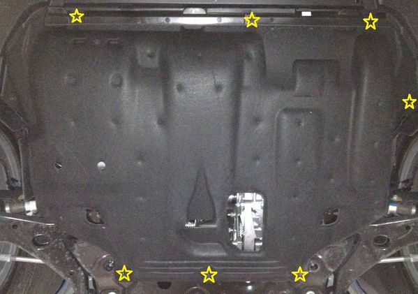
1. Using a T-30 Torx bit, remove the undertray by removing the screws (shown below) that hold it in place. You’ll need to first remove the small lip section (top of picture, below) followed by the rest of the undertray.
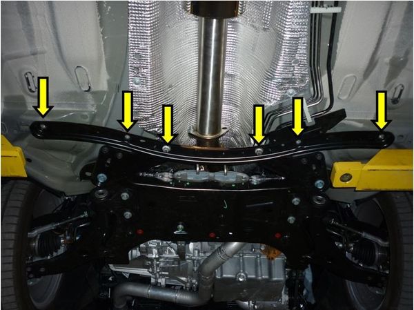
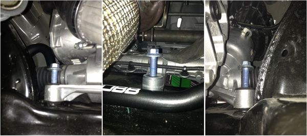
2. Remove the rear sub-frame cross brace. There are four (4) bolts and two (2) nuts that will require the use of a 15mm socket and/or wrench.
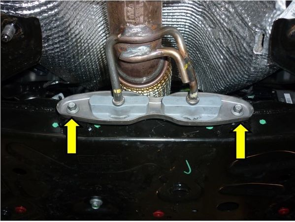
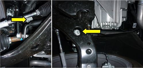
3. Remove the two (2) bolts that hold the downpipe isolator bracket using a 10mm socket or wrench.
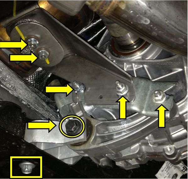
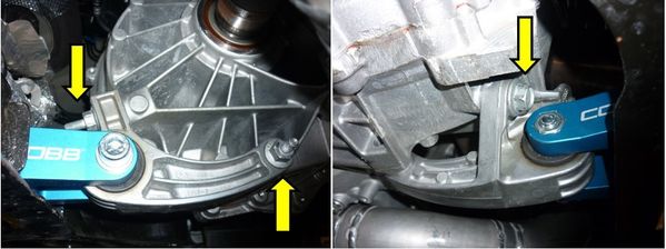
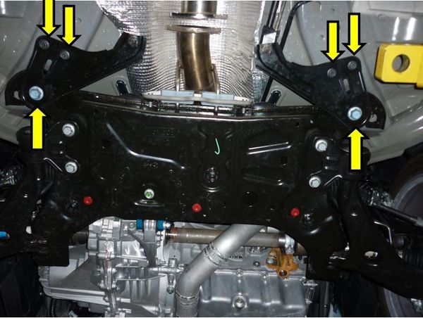
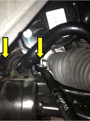
4. Remove the six (6) 13mm nuts that secure the downpipe brackets to the transmission (arrows, below). There is one right above the motor mount on the back of one of the brackets as well.
5. Remove the rear motor mount assembly by removing three (3) bolts from the transmission and one (1) bolt from the sub-frame. You will need a 15mm socket or wrench to do so.
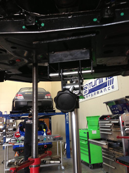
6. Put a jack stand under the rear of the motor to help support it.
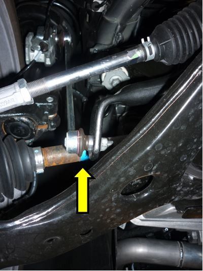
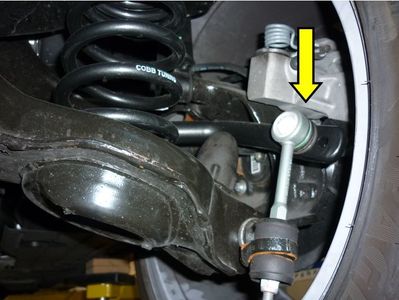
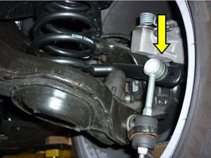
7. Using a 15mm wrench, remove the sway bar endlinks from the sway bar.
8. Remove the two (2) front sub-frame mounting bolts. You will need a very long extension with a 15mm socket to do so. There is a hole in the lower control arm you can use to access the bolts.
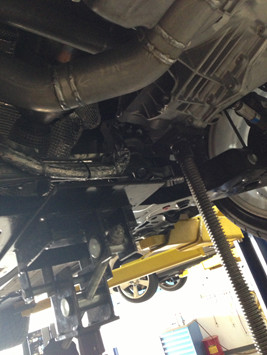
9. Support the sub-frame with a jack stand or jack.
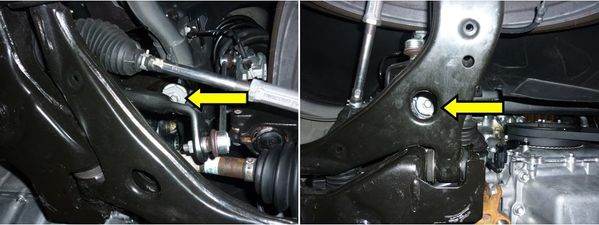
10. Remove the rear sub-frame mounting bolts. There will be two (2) 13mm bolts and one (1) 21mm bolt holding a plate on each side of the car.
11. Remove the three (3) steering rack mounting bolts using a 15mm socket or wrench.
12. Lower the sub-frame in order to access the sway bar bolts.
13. Remove the sway bar brackets using a 21mm socket to remove the two (2) nuts. You may need to hold the bolts on the underside of the sub-frame using a 18mm socket or wrench.
14. Remove the front sway bar.
Installation of the COBB Front Sway Bar
1. Grease the bushings using the provided grease. Cover the entire inner surface of the bushing. A medium to thick layer will work well. You should not have to use more than about ¼ to ½ of the tube for each bushing.
2. Install bushings and brackets on the COBB Front Sway Bar.
3. Install the COBB Front Sway Bar following the steps in reverse order of the removal of the Stock Front Sway Bar.
4. Torque the sway bar bushing bracket bolts to 115 Nm (85 ft-lbs).
5. Torque the steering rack bolts to 110 Nm (81 ft-lbs).
6. Torque the rear sub-frame 21mm bolts to 140 Nm (103 ft-lbs) and the 13mm bolts to 20 Nm (14.7 ft-lbs).
7. Torque the front sub-frame bolts to 115 Nm (85 ft-lbs).
8. Torque the rear motor mount assembly bolts to 86 Nm (63 ft-lbs).
9. Torque the downpipe isolator bracket bolts to 25 Nm (18 ft-lbs).
10. Torque the sway bar endlink nuts to 63 Nm (47 ft-lbs).
11. Torque the rear sub-frame cross brace bolts to 70 Nm (52 ft-lbs).
Removal of the Stock Rear Sway Bar
1. Remove the end links to the bar using a 15mm socket or wrench.
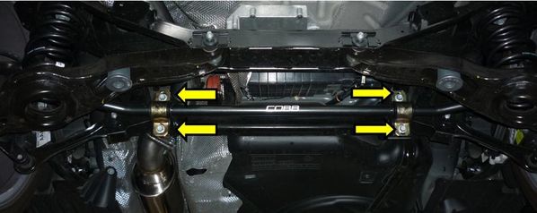
2. Remove the four (4) bolts holding the bushing brackets using a 13mm socket.
3. Remove the rear sway bar.
Installation of the COBB Rear Sway Bar
1. Grease the bushings using the provided grease. Cover the entire inner surface of the bushing. A medium to thick layer will work well. You should not have to use more than about ¼ to ½ of the tube for each bushing.
2. Install the bushings and brackets on the COBB Rear Sway Bar.
3. Install the COBB Rear Sway Bar.
4. Install the four (4) bolts holding the bushing brackets using a 13mm socket. Torque to 60 Nm (44 ft-lbs).
5. Install the end links to the bar using a 15mm socket or wrench. Torque to 63 Nm (47 ft-lbs).
6. Reinstall all four (4) wheels. Lower the vehicle off the lift or jack stands and torque the lug nuts to 135 Nm (100 ft-lbs).
7. Congratulations! You have completed the installation of the COBB Sway Bars for your 2013+ Ford Focus ST. Go out and enjoy!
Links
Ford Focus ST Map Notes
Helps to figure out which map you should be on given the parts installed to your car
Main Installation Listing
COBB Customer Support Web Support and Tech Articles: COBB Tuning Customer Support Center Email: support@cobbtuning.com Phone support available 9am to 6pm Monday-Thursday. 9am to 4pm Friday (CST) 866.922.3059 return to www.cobbtuning.comContact Us:
Copyright 2023 © COBB Tuning Products LLC. All Rights Reserved. | www.cobbtuning.com