772625 - Mazdaspeed3 Gen2 Front Mount Intercooler
- Brandyn Mowat

772625 – Mazdaspeed3 Gen2 Front Mount Intercooler
Mazda3 MPS 2010 - 2012
Mazdaspeed Axela 2010 - 2012
Mazdaspeed3 2010 - 2013

Congratulations on your purchase of the COBB Tuning Mazdaspeed Gen 2 Intercooler! The following instructions will assist you through the installation process. Please read them BEFORE beginning the install to familiarize yourself with the steps and tools needed. If you feel you cannot properly perform this installation, we HIGHLY recommend you take the vehicle to a qualified and experienced automotive technician.
IMPORTANT! Installing this kit will require custom tuning or utilizing an appropriate Stage Power Package map if you have a matching mechanical configuration. Please consult with COBB or an authorized ProTuner in your area if you have any questions!
Table of Contents
Parts List
- Intercooler Core
- (2) Intercooler Mounting Brackets
- (3) Intercooler Charge Pipes
- 90 Degree Silicone Reducer
- 2.75" - 2.5"
- (3) 2.5" Straight Couplers
- (8) 2793T-Bolt Clamp 70-78mm
- 2792 T-Bolt Clamp 60-68mm
- 2794 T-Bolt Clamp 73-81mm
- Stencil for MS3 FMIC
- Shift Wight
- Pipe Sticker for MS3 FMIC
- (4) 1/4" - 20 Cap Screws
- (4) 1/4" Lock Washers
- (2) M8 - 1.25 x 16 Cap Screws
- (2) 8mm Lock Washer
Tools Needed
- Phillips head screwdriver
- Flathead screwdriver
3/8" ratchet
3/8" 8mm socket
3/8" 10mm deep socket
3/8" 12" extension
3/8" 6" extension
- 10mm combination wrench
- 12mm combination wrench
- Razor Knife or snips to cut plastic
Before You Begin
We suggest checking with the dealer to see if your car may be a candidate for the Mazda recall on one or more of the engine mounts, or invest in some stiffer after market engine mounts before starting on the installation of the COBB FMIC. Excessive engine movement may cause a properly fitting kit to rub
Front Bumper Removal
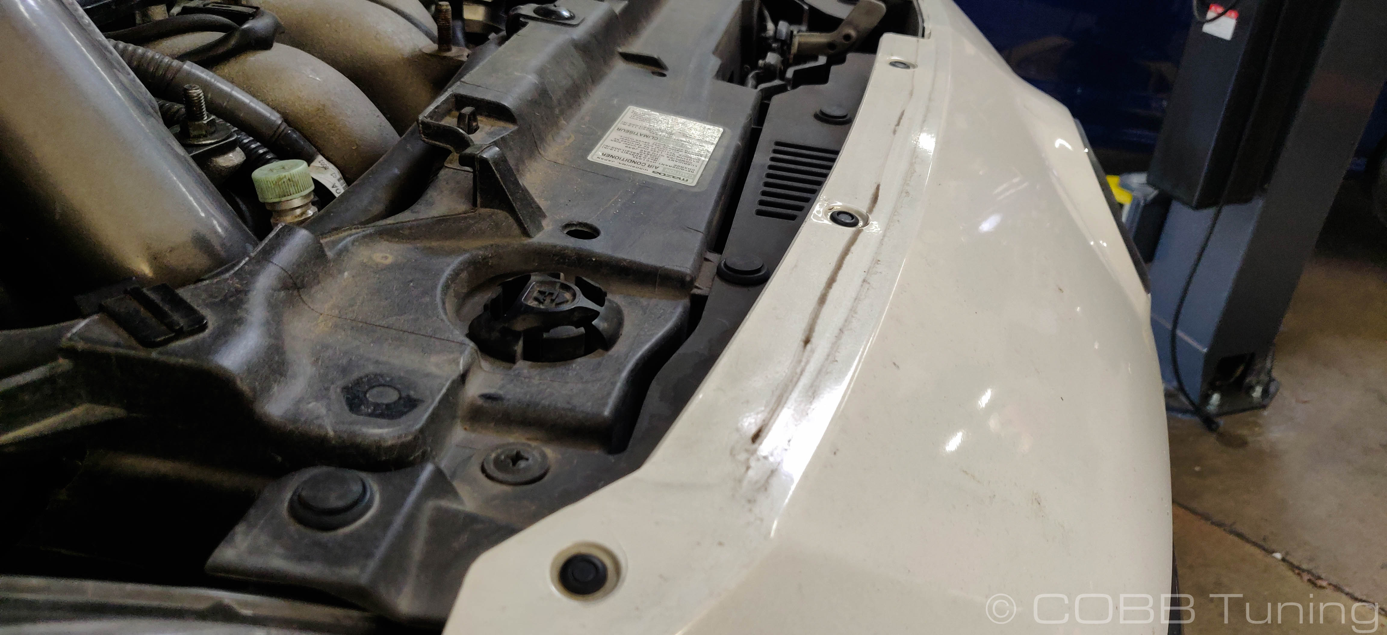
- Start off by removing the two Phillips head fasteners on top of the front bumper cover. Then remove the six plastic rivet fasteners from the front bumper using a flathead screwdriver or specialty tool.
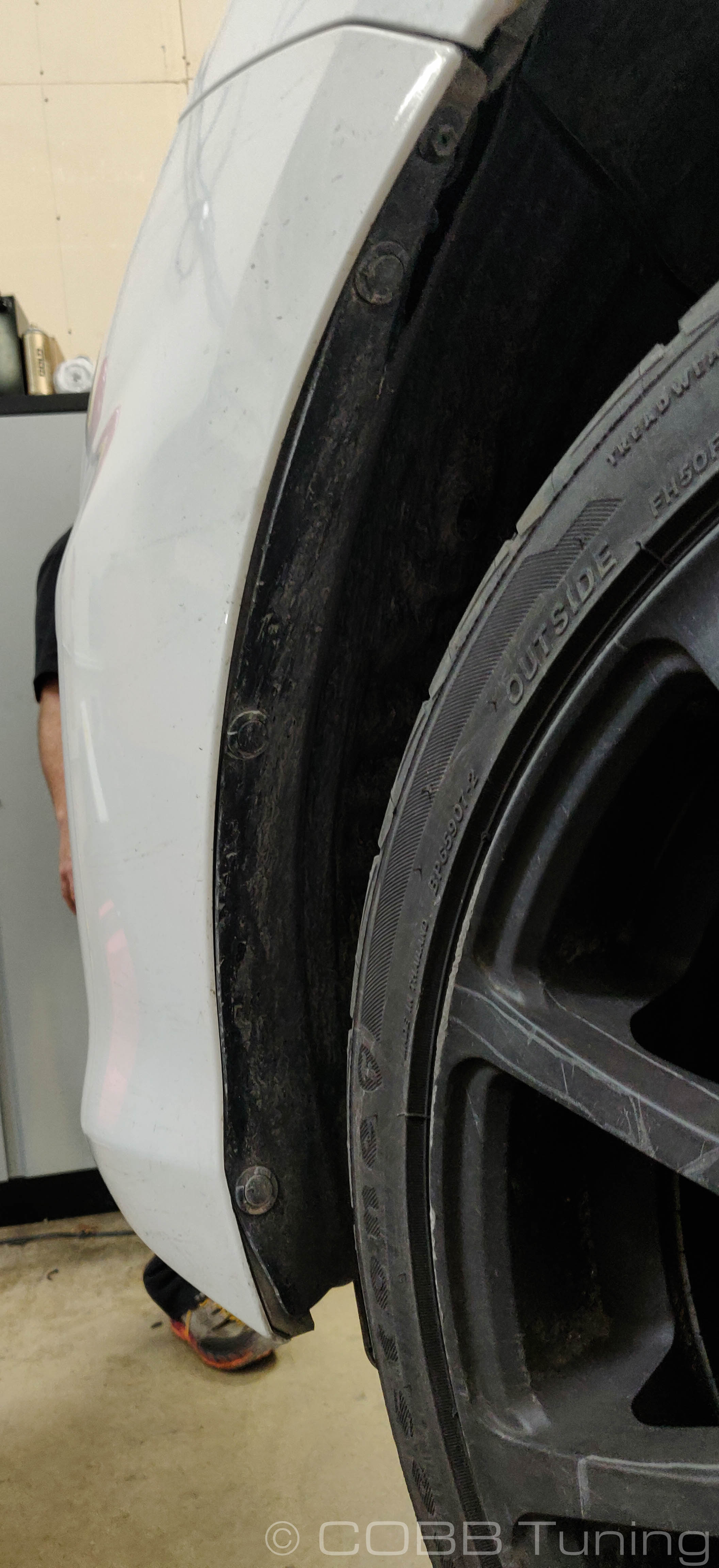
- Now move to the front left wheel and remove the three plastic Phillips head fasteners and one 8mm screw that attaches the fender liner to the front bumper. Repeat this step for the passenger side.
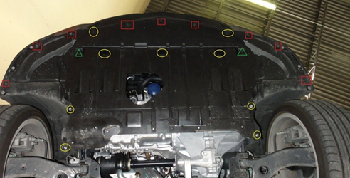
- Now move underneath the car and completely remove the front undertray by removing three plastic fasteners, nine 8mm screws and nine 10mm bolts.
- With the front undertray removed, you will need to disconnect the fog light connectors on both sides of the car, as well as several plastic retaining clips that hold the wire harness in place.
- The bumper is now ready to be removed. Start by pulling the corners of the bumper away from the quarter panel on each side of the car. Pull on the sides gently until it comes free. Once both sides are free, the bumper should lift away from the car. Be careful to not let it hit your quarter panels on the way out and make sure to rest the bumper in a safe place where it won't get bumped or scratched.
Removal of Factory Intercooler System
- With a 10mm socket, remove the two bolts that secure the intercooler cover to the motor and remove the cover.
- With a 12mm socket, remove the three nuts that secure the intercooler to the top of the motor. Two are located at the front of the intercooler that mounts it to the intake manifold and the third is located at the back of the intercooler bracket over the exhaust manifold.
- Using a 10mm socket or Phillips head screwdriver, loosen the hose clamps that secure the charge piping to the intercooler. They don't need to be completely undone, just loose enough so that the intercooler can slide out of the tube. There is one charge tube coming from the turbo and going in to the intercooler at the back of the motor. The second tube is at the front of the motor and feeds into the throttle body. At this point, only loosen the clamp that is closest to the intercooler on the pipes.
- Using a set of pliers, remove the tension clamp that secures the reirculation tube to the bypass valve. Remove the hose from the BPV.
- The intercooler should now be loose and can be removed. It may take some back and forth motion in order to loosen it from the charge tubes depending on how loose you made the hose clamps.
- The last step is going to be to loosen the two remaining clamps holding the charge pipe. There should be one securing the hot side charge tube onto the turbo and one securing it to the throttle body. Loosen both and remove the tube and clamps from the engine bay.
Installation of COBB Front Mount Intercooler
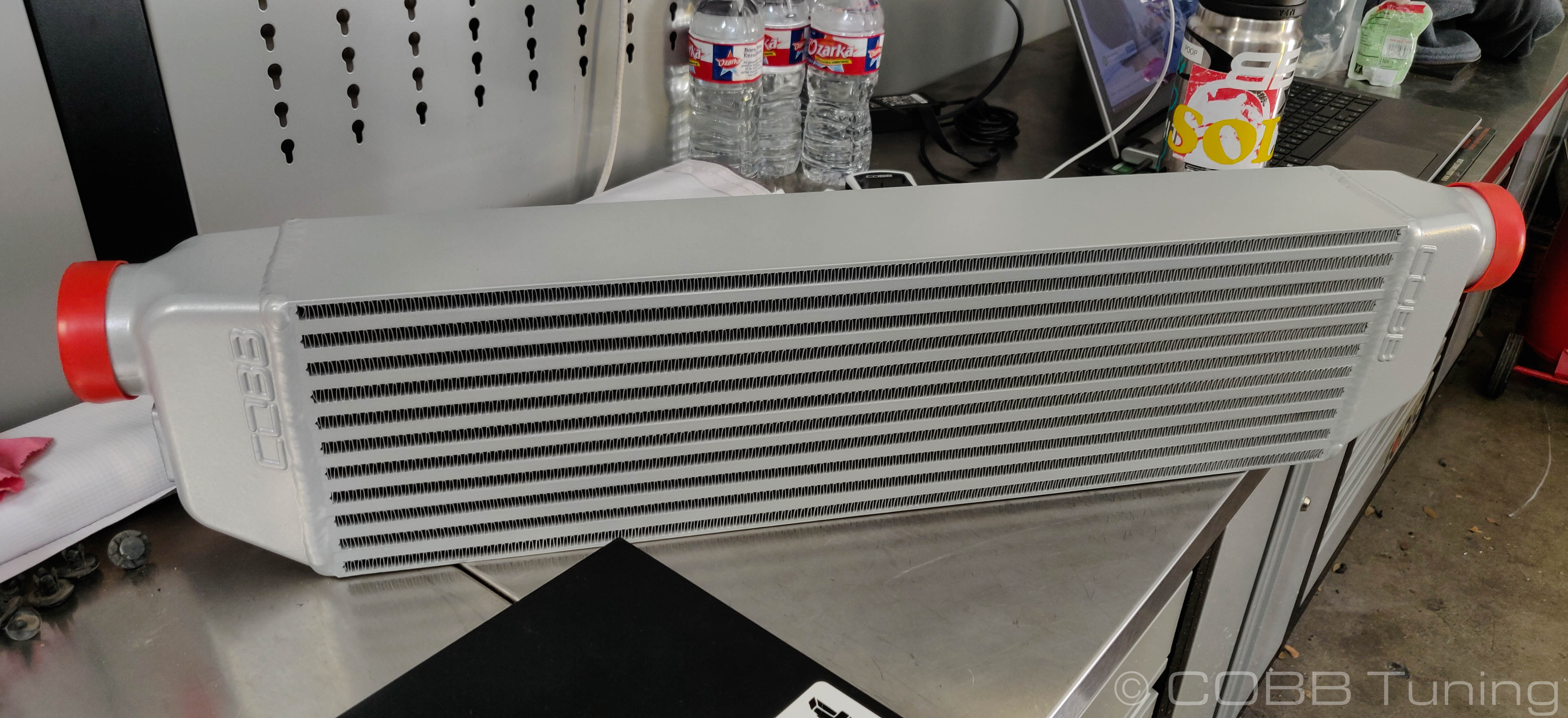
- Optional: If you want to add that special flare and show off your COBB FMIC you will want to take this opportunity to apply a COBB logo to your
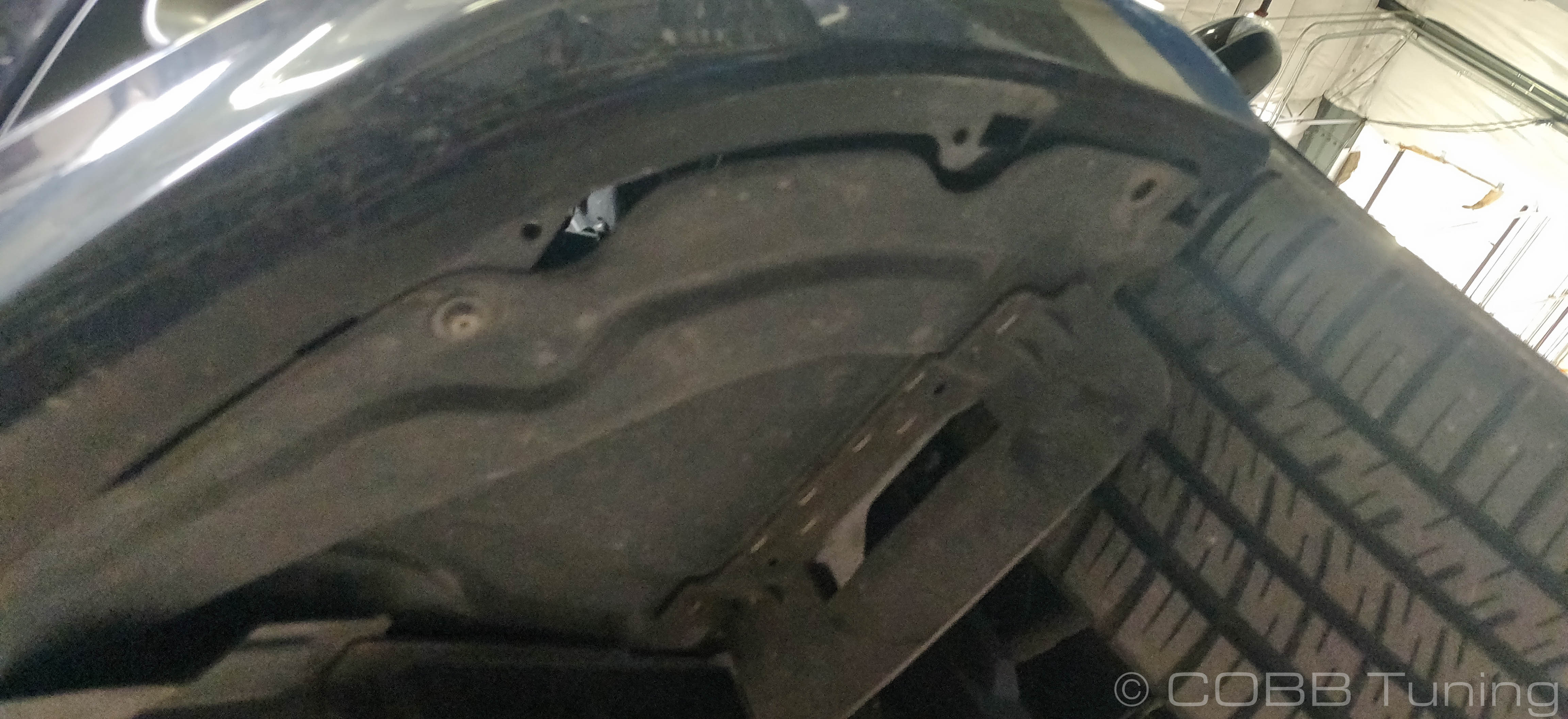
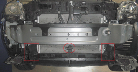
intercooler using the supplied stencil. It is cut so that the logo should be centered when everything is lined up. Use your own judgement in paint preparation and application. - Now with the front bumper removed, you will need to make room for the intercooler and piping by removing the left and right side plastic ducting/splash guards. There are two plastic retainers and three 10mm bolts on the left side ducting as well as two 10mm bolts on the right side. You will also need to unclip the harness for the Ambient Air Temperature sensor and get it out of the way.
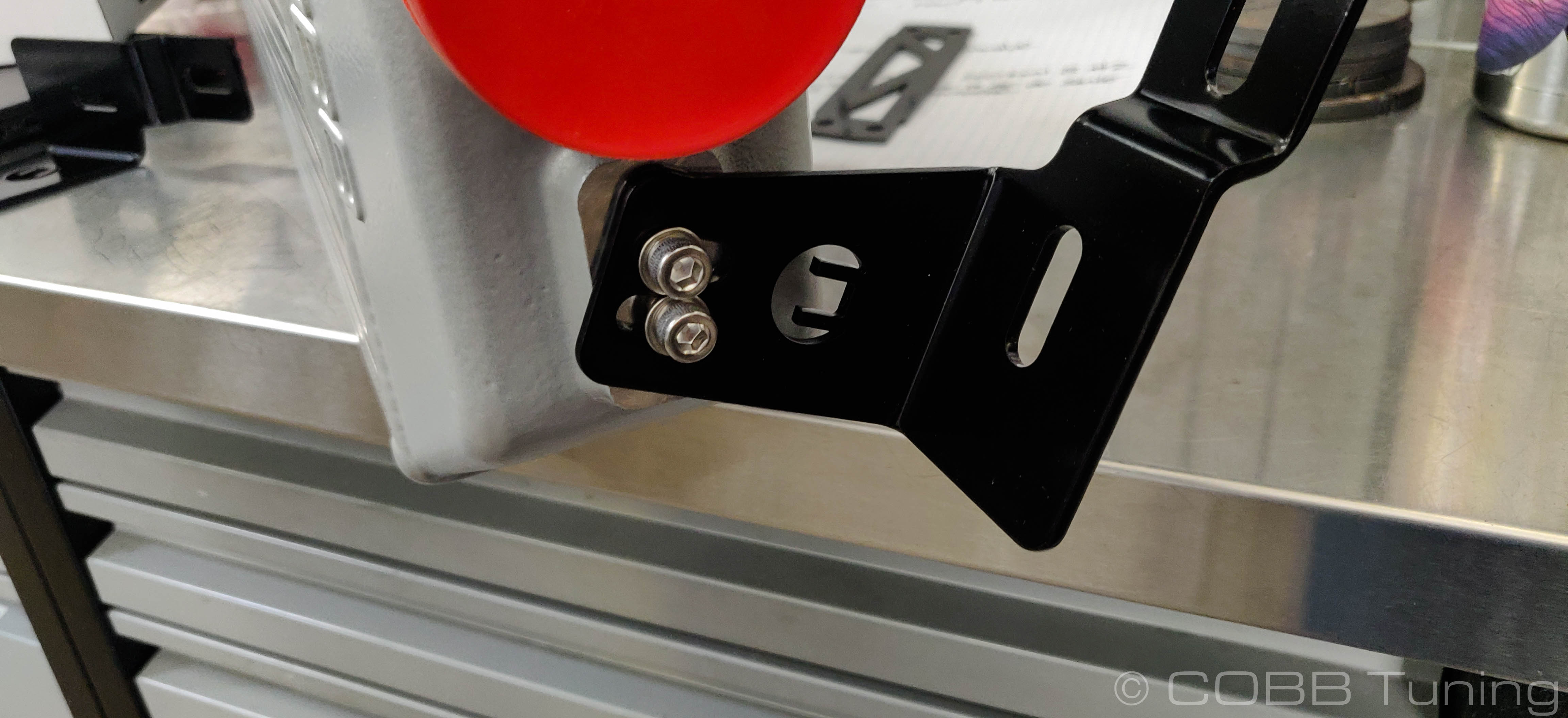
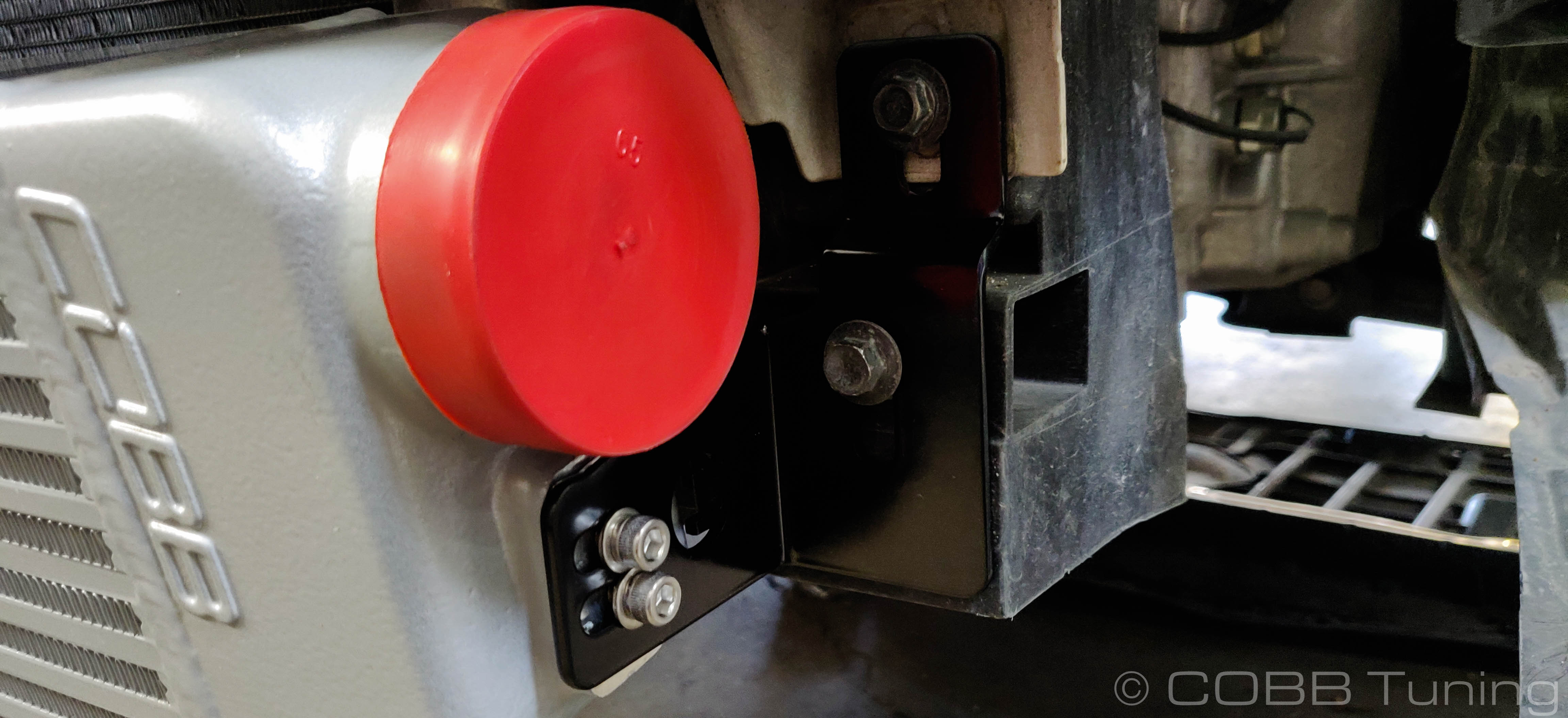
Loosely mount the intercooler mounting brackets to the intercooler using the supplied 1/4" - 20 stainless steel socket head cap screws and lock washers, along with a 3/16" Allen wrench in the fashion shown below. Repeat on the opposite side.
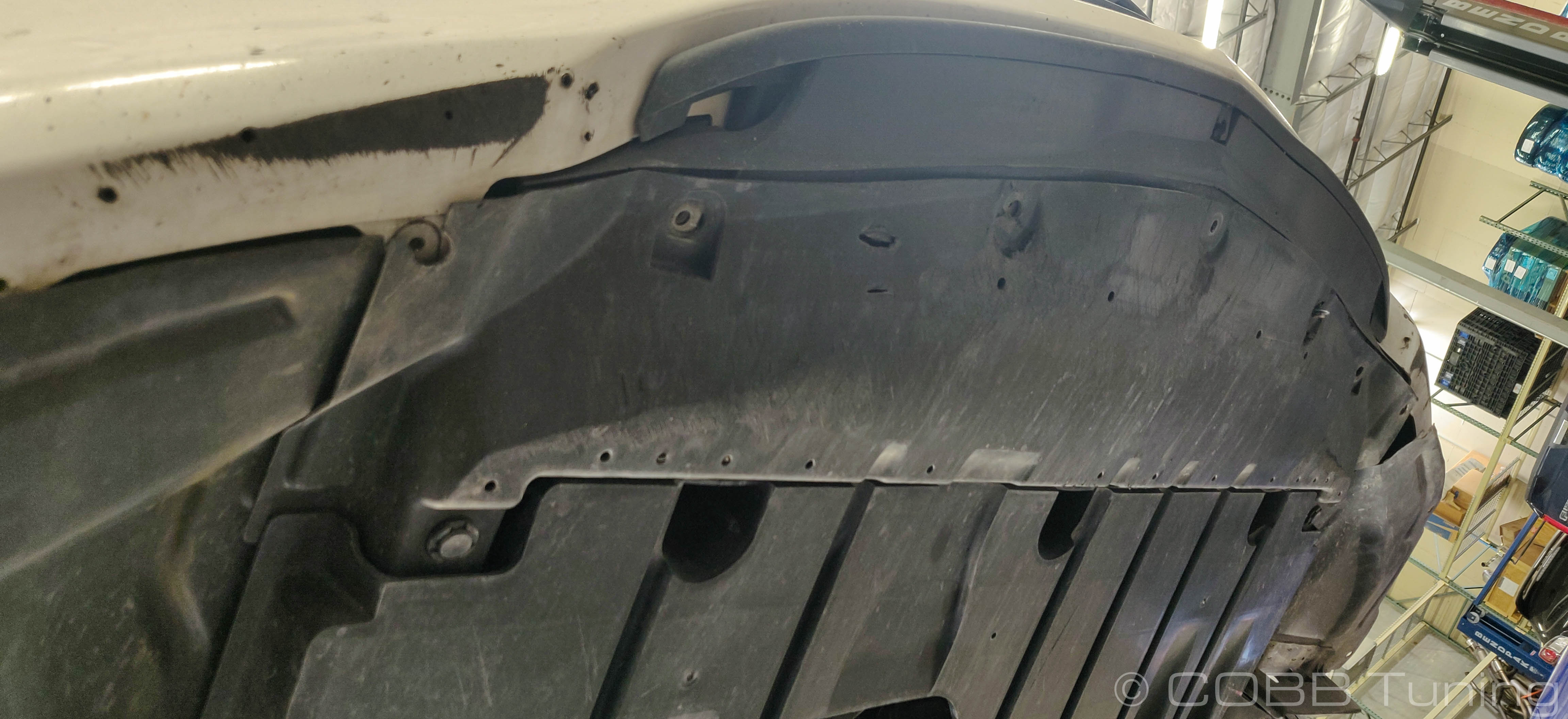
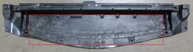
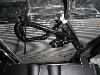
- You will now need to do some trimming of the forward undertray to make room for the intercooler core. Using a cutting device (snips, cut-off wheel, dremel, careful use of a razor blade) remove all the webbing material from the undertray as shown below. The closer to the base of the tray you can get, the better.
- Now that you've made the necessary room for your new intercooler, it is time to get it mounted to the vehicle. Using the supplied 10mm bolts and flat washers, mount the intercooler to the front of the car utilizing the mounting holes from the previously removed plastic ducting shown below. Mount the core loosely at all points so that you can make adjustments.
- With the intercooler mounted to the vehicle you can now work on getting it positioned properly under factory crash bar. It is critical that the core is situated as HIGH as possible so that the top of the core is as close to the crash bar as possible. You will need all the clearance you can get underneath to get the undertray mounted with it in place. Before you tighten the brackets to the core, raise it up as high as possible even making contact with the crash bar before tightening. This is because when you let go it will still settle a small amount.
- With the core now mounted to the vehicle, use a 3/16" Allen wrench in order to tighten the core to the mounting brackets. We recommend tipping the top of the core forward a small amount to allow a little bit of extra clearance for the undertray mounting screws.
Installation of COBB Tuning FMIC Charge Piping
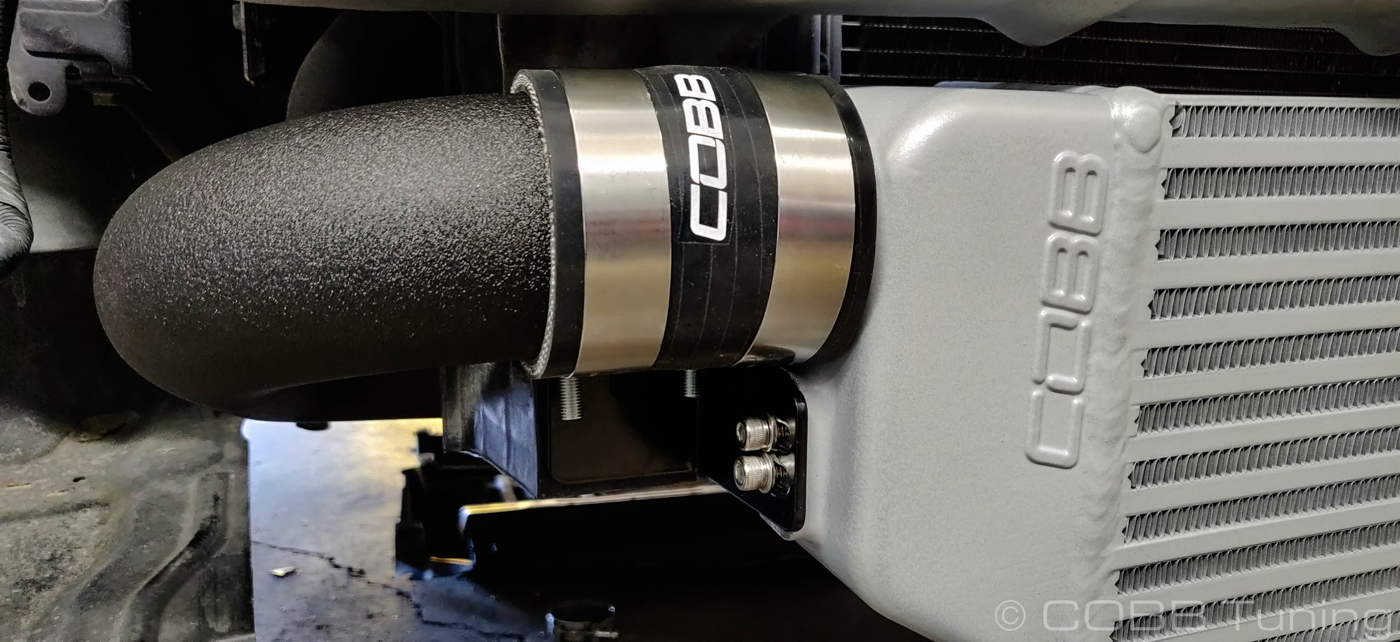
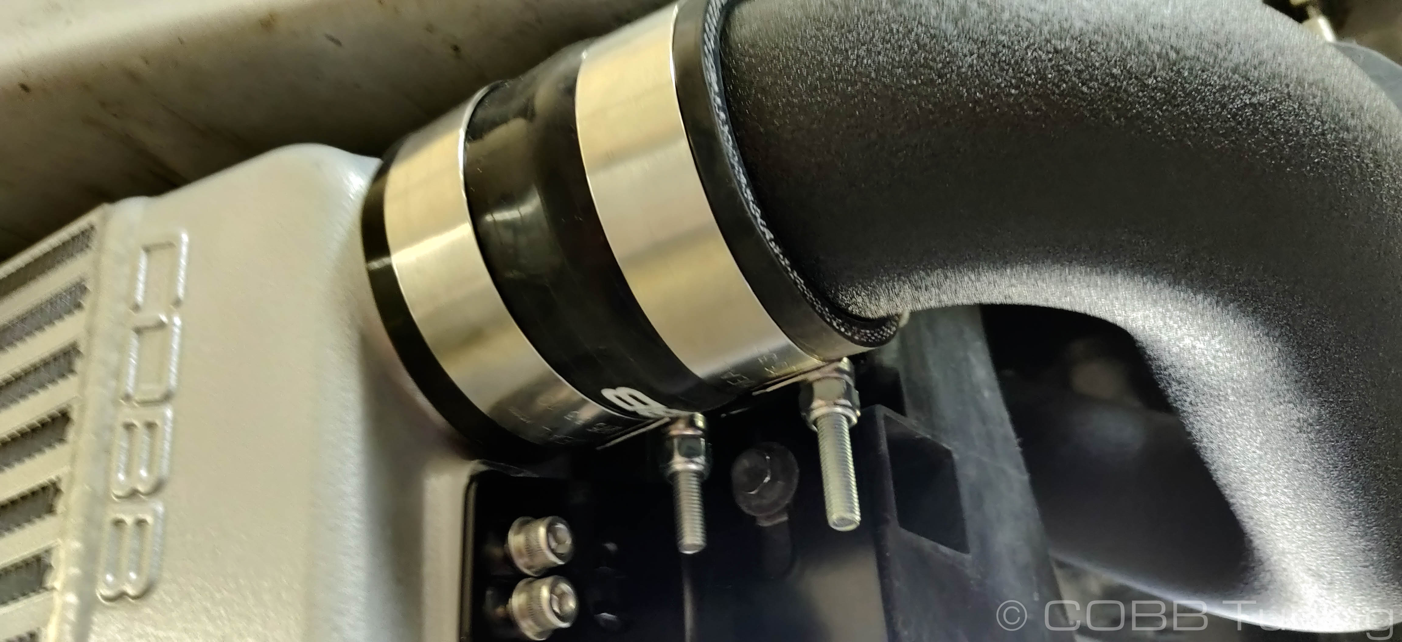
- To start off, install a 2.5" straight coupler onto the inlet and outlet of the intercooler and secure them using the 2793 t-bolt clamp. It is recommended that the thread shank be pointed downward and towards the back of the vehicle for clearance purposes.
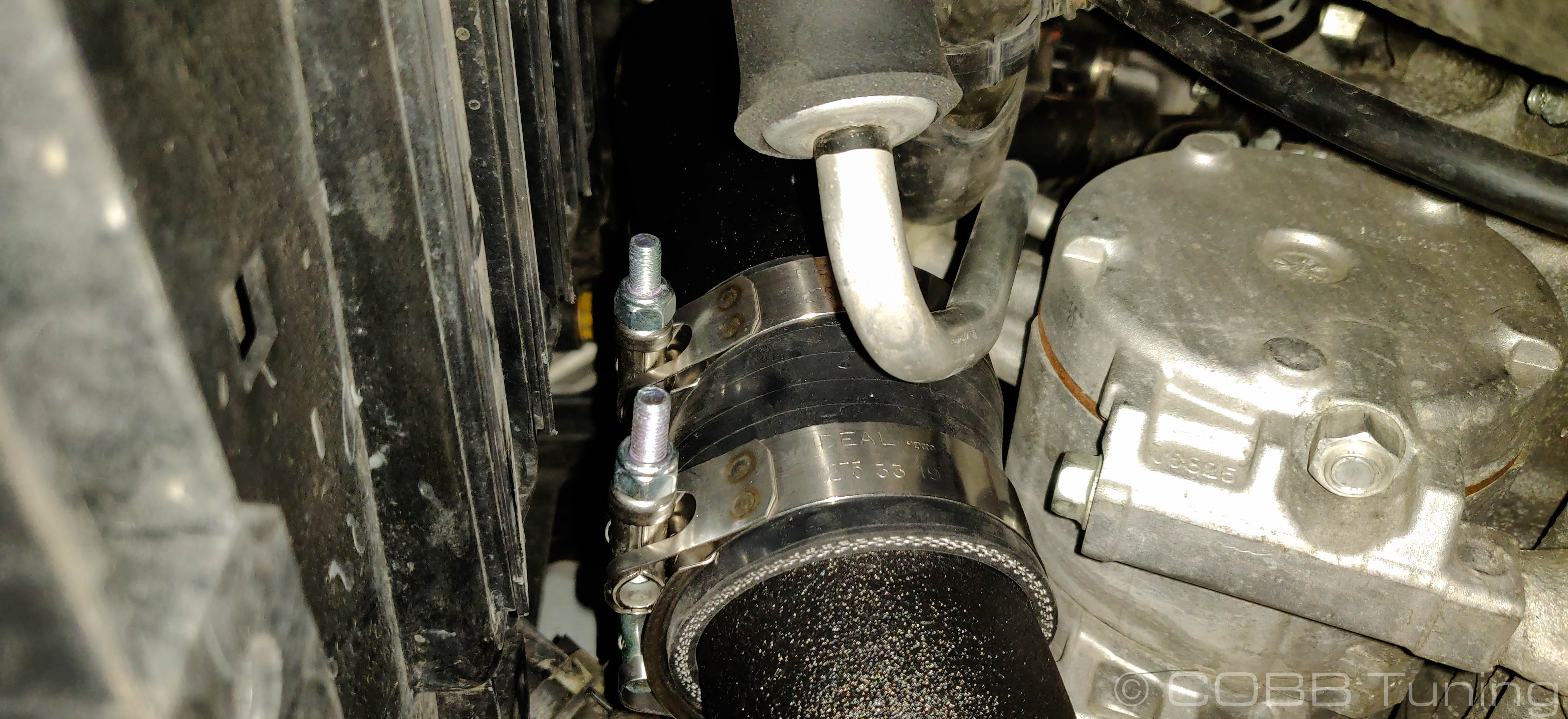
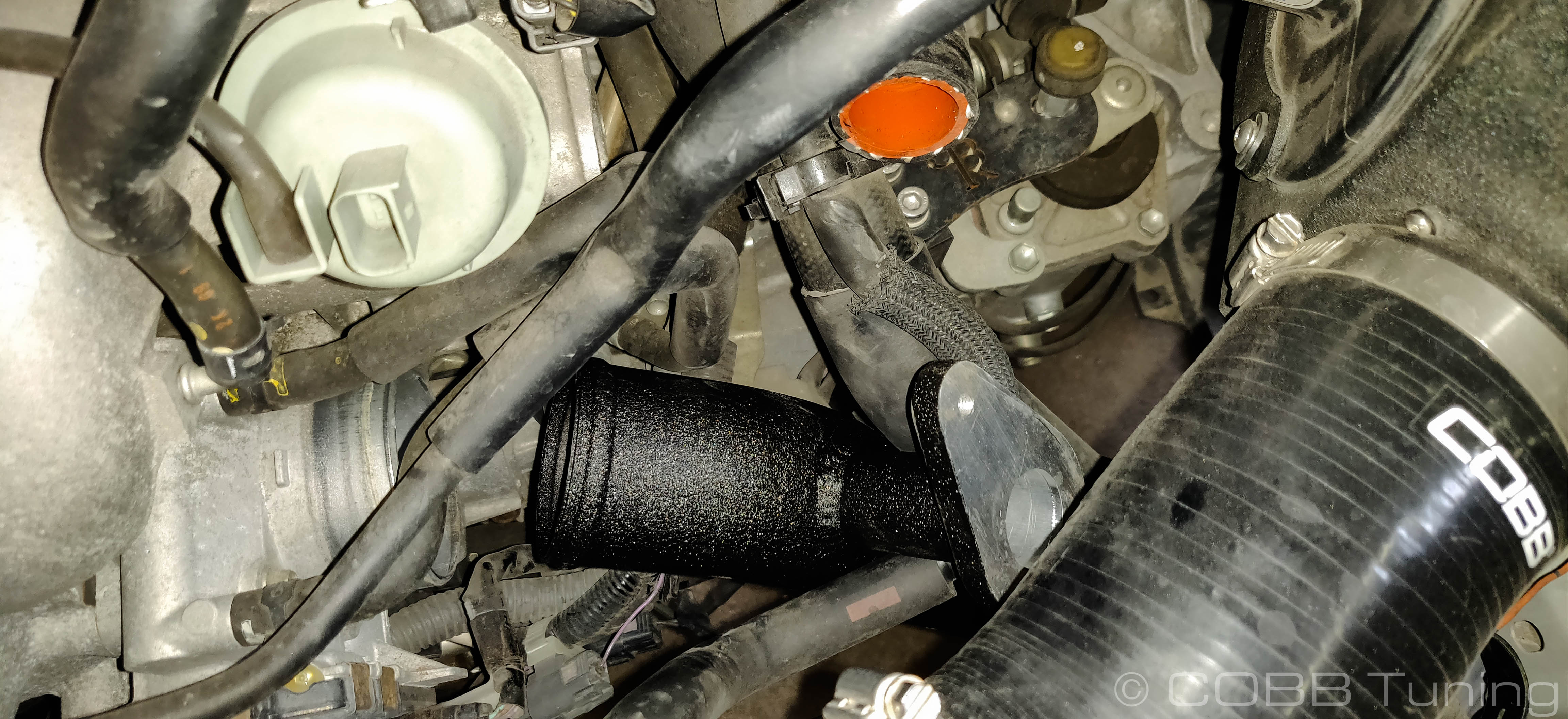
- Next, install the 90-degree silicone reducer onto the turbo. Install the 2792 t-bolt clamp onto the reducer, but leave it loose so you can adjust the angle once the hot pipe is installed.
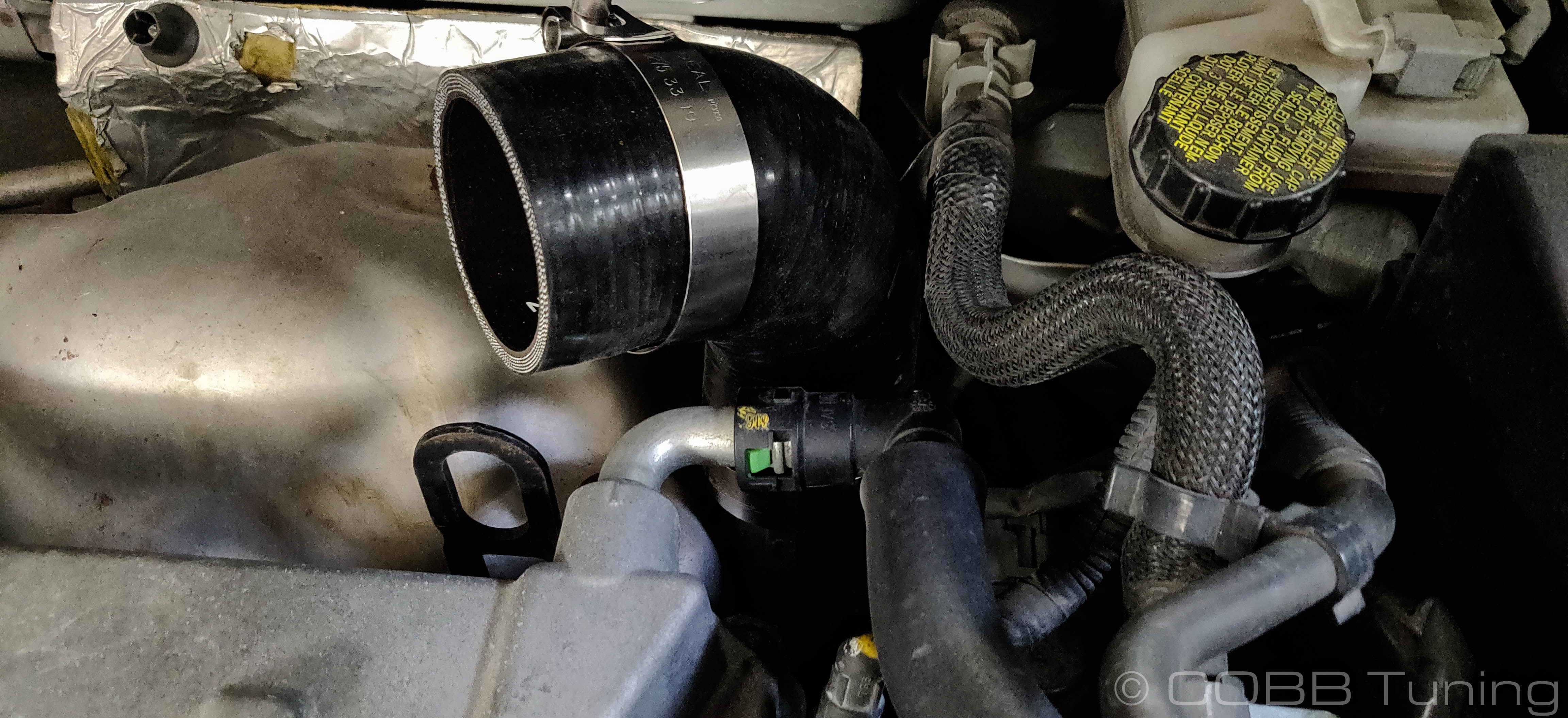
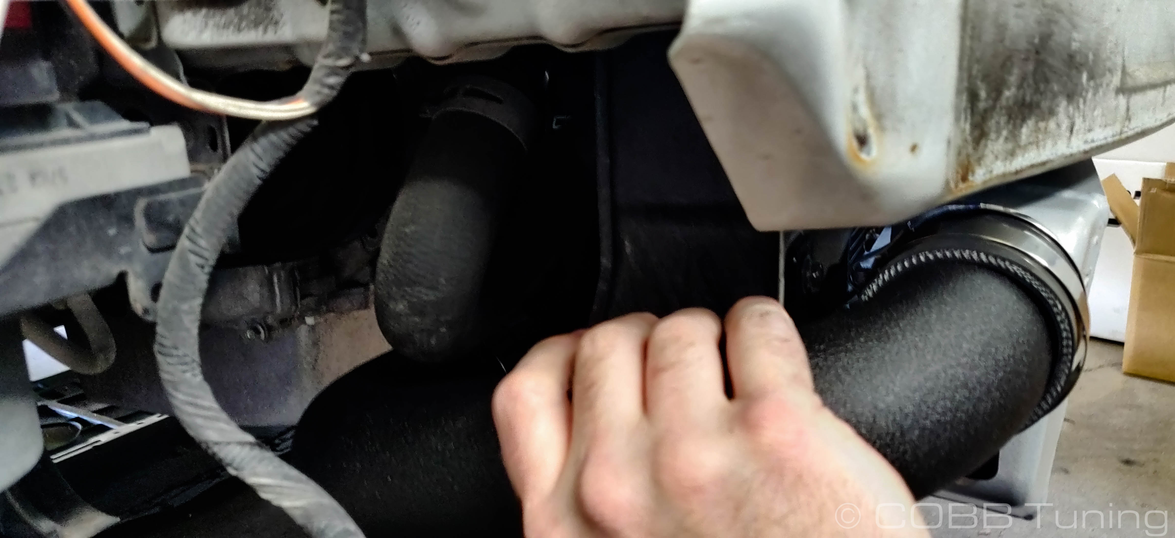
- Next we can begin placing the charge piping. Starting with the hot pipe that is the longest and has a bracked welded on the side, this one should fit over one of the old intercooler mounts and go up to the reducer from the turbo. Once the pipe is fitted in place, loosely install the 2793 t-bolt clamps on both ends.
- Moving on, install the smallest of the three pipes to bridge the gap between the pipe you just installed and the intercooler itself. Fit the pipe into the the two couplers and tighten down.
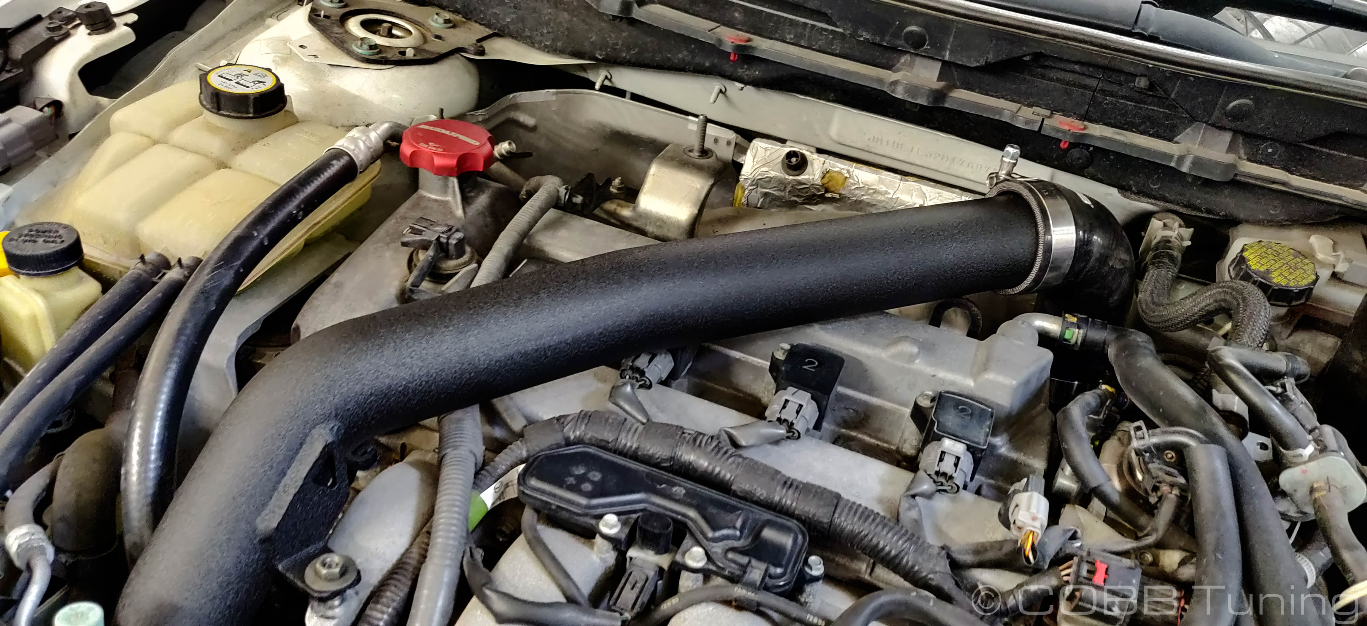
- Next, install the 2.75" - 2.5" silicone straight reducer onto the throttle body. Make sure it is fully seated onto the throttle body and install and tighten the clamp.
- Finally, install the last charge pipe going from the intercooler to the throttle body, using a 2793 t-bolt clamp on either end to tighten down.
- Now go ahead and install the bypass valve onto the flange and reinstall the recirculation tube.
- With everything installed, it's a good time to go through and make sure all the pipes have a good amount of clearance everywhere, and that they're in the coupler as far as possible. Once you're ready tighten everything down.
- The ambient air temperature sensor must be relocated before installing the bumper back onto the vehicle. We've included a few zip ties to get it out of the way. Place it in such a way that the sensor can get the most fresh air possible, and as little hot airflow from the engine as possible. There are several locations to place it but we chose to do it this way.
- Start the car and check for leaks. If the car is not idling well you likely have a leak somewhere causing problems.
- Once everything is running well reinstall the bumper and undertrays in the reverse order from removal, you may need to reorient clamps depending on your bumper clearance.
- Flash the appropriate map for your FMIC.
- Go out and enjoy!
CARB Sticker Installation (On CARB Certified Applications)
This product is covered under multiple CARB EO letters. For additional information on CARB EO options for your Mazda, check out our page CARB EO numbers for COBB Mazda Products
Install the supplied CARB sticker on an easily viewable space that won't be susceptible to large amounts of heat. We recommend on the radiator core support, or the underside of the hood.
Links
COBB Product Install Instructions for Mazda Vehicles
Main Installation Instruction Repository for Mazda Parts
Link to Mazda Map Notes to see what map you should be on given the parts you've added
COBB Customer Support Web Support and Tech Articles: COBB Tuning Customer Support Center Email: support@cobbtuning.com Phone support available 9am to 6pm Monday-Thursday. 9am to 4pm Friday (CST) 866.922.3059 return to www.cobbtuning.comContact Us:
Copyright 2025 © COBB Tuning Products LLC. All Rights Reserved. | www.cobbtuning.com