MAZDASPEED Tuning Guide
- Mike McGinnis
- Brandyn Mowat

![]()
MAZDASPEED Tuning Guide

The following guide is designed to present experienced tuners with an efficient calibration procedure specific to this Accesstuner application.
If you are new to engine management system tuning, we suggest gaining general knowledge and understanding of both calibration and engine dynamics before proceeding at your own risk.
1st – Update your Accessport firmware, review some helpful documents, and start with the appropriate base map
- Update the firmware on your Accessport to the latest version by following instructions available here.
- Browse to the Accessport support home which includes information on setting up data logging, a key component of tuning and monitoring your engine.
- Review the MAZDASPEED vehicle info and maintenance documents. They include spark plug and breather system info, Technical Service Bulletin (TSB) information from Mazda and more. All mechanical preparation should be performed before starting the tuning process.
- We have also included a Help File you can access by pressing the F1 key while the Accesstuner software is open. There's a detailed description of all tables and tuning tips for most tables.
- Please start with a base map that best fits the hardware installed on your vehicle and fuel being used. That information is included in the map description viewable using the Accessport or Accessport Manager software. Alternatively you can review map notes on the COBB website under the “MAPS” section. Be sure to enter your vehicle type so maps for your platform are displayed.
- After completing the above, open your Accesstuner software and complete any available software updates.
- Please make sure the Weighted Interpolation box has been checked. This setting is found in the Display tab of the Configure Options menu, which can be accessed in the software by pressing CTRL+F key. Selecting this will cause Live Trace to appear smoother so you can better identify the current operating condition.
- We have written a detailed description for all tables. You can view this information by enabling the Table Description option under the View menu or by pressing CTRL-F1 while the particular table you want to learn about is highlighted in the table list located on the left hand side of the Accesstuner software.
2nd – Establish safe load/boost targets and limits along with other base settings
Factory boost and load targets are generally a safe starting point. We'll discuss boost/load targeting more in depth later.
Select appropriate boost and load limits which help protect the engine should boost or load exceed your targets by an unacceptable value. Several tables exist within the ECU which control when the engine cuts fuel if the engine exceeds limits. If you determine 3 psi over target is unacceptable at all engine speeds, set your limit tables to mirror your boost curve, +3 psi. The Boost Limits table will cut fuel to the engine if the applicable boost value is exceeded.
If your setup is capable of exceeding the max load values in the Calc. Load Max A and B tables, or Closed Loop Max Load Limit A-C, and you want to allow this, now is the time to adjust limits accordingly.
The Abs Load Limits – Fuel Cut table will cut fuel if the engine exceeds the load values in this table. Since this ECU operates based on torque request, set appropriate limits not just for boost, but for calculated load too. This is a good way to keep the engine operating within the limits of the fuel system and other components. While the ECU will compensate for a drop in fuel pressure, a drop far below target can lead to a lean condition or detonation.

Please be sure to verify your fueling capacity is capable of keeping up with fueling demand before you start calibrating. Fueling needs can be calculated in advance if you know expected engine output. During WOT (Wide Open Throttle) engine operation if you see your HPFP Actual Pressure drop below 1300psi, we highly suggest you upgrade your HPFP (High Pressure Fuel Pump). The stock HPFP can usually maintain ~1500-1600psi on a stock vehicle. Most high-flow HPFPs can achieve more. Keep in mind some setups will require upgrade of the in tank fuel pump as well.
If you upgrade the fuel pump and wish to alter target fuel pressure, please be mindful of safety as well as the fuel pressure high limit threshold which triggers a check engine code.
Next set primary rev limit, launch control limit and flat foot shift limit values. If you do not wish to use launch control or flat shifting, setting those values greater than the primary rev limit will avoid engaging those systems.
If you are using a non-standard MAP sensor, now is the time to enter calibration data to ensure accurate readings.
The formula for MAP sensor calibration is: (MAP Voltage * Component A * Component B) - Offset = MAP kPa
Generally MAP sensor calibration data is provided as a slope and offset. To make your life easier, we suggest setting either Component A or B to 1 so it has no effect, allowing you to enter the slope and offset as provided to you, as long as it's in the correct unit (kPa).
Stock data: Component A: 230.0, Component B: 0.24, Offset 1.65
Example: (MAP V * 230 * .24) - 1.65 simplifies to (MAP V * 55.2) - 1.65 so 55.2 is your slope and 1.65 your offset.
Set fuel, ignition timing, boost settings, and other settings to known safe values. It’s best to start conservative, then gradually make your calibration more aggressive once you have MAF scaling and other tables dialed in.
Keep in mind you must reflash the ECU for changes to take effect.
3rd – Recording a data log, establish or verify the proper MAF calibration settings
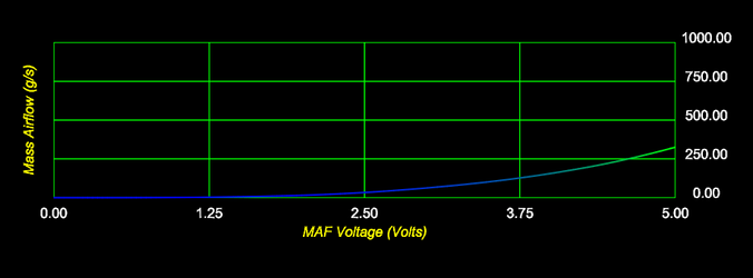
The MAF Calibration table is filled with air mass values corresponding to MAF sensor output voltage. These mass air values allow the ECU to properly calculate the mass of the fuel it needs to inject into the engine to achieve the air/fuel ratio dictated in the Fuel Commanded EQ table active at the time or by the closed loop control target. The data in the MAF calibration table is represented in grams per second. Under normal idle and light throttle closed loop conditions the ECU is always going to try and hit 1 Lambda (the stoichiometric ratio of the fuel you are running). You will be most familiar with the associated gasoline air/fuel ratio of 14.68:1 A/F, which is an air mass of 14.68 grams to every 1 gram of fuel. Keep in mind this is for e0 (0% ethanol) fuel, and many stations now serve e10 or even e15 fuel which have different stoichiometric ratios.
If your vehicle is not equipped with the stock intake system, the stock calibration values will no longer be appropriate. MAF housing diameter and how air flows past the sensor are both critical. If the diameter is different from stock you'll want to scale all MAF calibration values before starting the engine. Start the engine and begin the following process designed to refine your MAF scaling table.
This test should be done carefully. Allow the vehicle to idle for a few minutes and do not proceed until it is up to normal operating temperature (180+ F). Set the Accessport or Accesstuner software up to data log the monitors listed above. Be sure to have MAF Airflow, engine speed, STFT, and LTFT displayed on the screen as you prepare to log. Start in 2nd gear at 1500 RPM then very slowly modulate throttle from there over the next several seconds. Accelerate at a steady rate until you exceed 100 grams/sec air mass flow or reach 6000 RPM. If you get to 6000 RPM before exceeding 100 grams/sec, try again this time applying a bit more throttle initially so you sweep from ~40 to 100+ grams/second and skip the lower range. After you have completed this test up to 100 grams/sec, please put the car in neutral and allow the car to idle for a few seconds. Then open the throttle while the car is in neutral until you exceed 30 grams/sec, then stop the data log. This will allow you to see the fuel trim learning the stock ECU is using to compensate for the intake system that is installed. Ideally, you want your LTFT values to be closer to zero. Anything +/- 8% is generally considered acceptable for this platform, but closer to 0% is ideal. Do not go into boost significantly and try to avoid sudden throttle transitions. Do not allow STFT (Short Term Fuel Trim) to reach +25% or -25% more than momentarily. If you achieve these values more than momentarily, revisit your initial MAF scaling and/or review the mechanical condition of the vehicle before continuing because that should not occur.
Observe the various adjustments which have been made by the ECU at various voltage values along the MAF curve, some long term, some short term. The long term trims affect regions of the MAF calibration rather than individual cell break points. The break points for each long term trim range can be viewed under the Closed Loop Tables -> LTFT Learning Zone A-F. Keep in mind they are not the same for all models.
You want the combination of short and long term A/F trims to be as close to 0 as possible. For example, if STFT is +5% and LTFT is -5%, the trims negate each other. No trim is applied to fuel injector pulse width and no adjustment to the MAF scaling is required. In time, opposite STFT and LTFT will result in both values trending towards 0. If however STFT is +5% and LTFT is 0% while steady state, the air mass calibrated for that MAF V is insufficient. Increase the grams/sec value for that MAF voltage until your combined fuel trims are 0 or close to zero. Look at the combined % correction of the STFT & LTFT in a data log. If the total is +6%, you know 6% more air mass is entering the engine at that MAF V than your MAF calibration table currently defines. Highlight the MAF Calibration table cell at this MAF voltage and hit the “M” key. You will then be prompted to enter a floating point value. Multiplying by 1.06 adds the 6% air mass required for this correction. Telling your ECU this MAF voltage correlates to 6% greater mass of air entering the engine results in 6% more mass of fuel being injected to maintain the target air/fuel ratio called for without relying on closed loop trimming. The less your tune relies on closed loop correction, the better the engine will run.
On the other hand if the STFT + LTFT total is -4%, less air mass is entering the engine than your MAF calibration currently defines, causing the fuel trimming system to reduce injector pulse width to keep AFR actual on target. Highlight the MAF Calibration cell for that particular MAF voltage, hit the “M” key, and enter 0.96 to subtract 4% air mass. Remember your changes do not take effect until you reflash the ECU. For best efficiency we suggest correcting cells throughout the entire airflow range being tested prior to reflashing. After the flash is complete, start the engine and let idle speed and fuel trims stabilize. Repeat the MAF scaling process until you've reached your desired level of precision. 1-3 flashes should be all that's necessary to complete this step of the tuning process. Keep in mind your MAF scaling curve should be smooth. Use the Table Graph Window to help you identify outlying values. If you have a properly designed intake system, the MAF Calibration should look similar in shape to your stock MAF Calibration graph even if the new MAF housing is larger in diameter and allows for measurement of significantly more airflow.
Be sure to keep your throttle movement as steady as possible during this process. Rapid movements of the throttle may employ tip-in fuel enrichment and may skew your fuel trims.
After completing the above in 2nd gear, run the vehicle under more varied conditions. Operate the engine with A/C on and off, use different gears and vary load to make sure your calibrations are more complete.
Your trim values will always adjust back and forth (+/-). Do not beat yourself up trying to achieve 0 correction. It is impossible. Atmospheric, gasoline, etc. changes will not allow for perfection. This is why closed loop operation is employed by modern vehicles. If your calibration allows for +/-5% LTFT, no excessive STFT during steady state, you've done well.
Changing the MAF Calibration will change your calculated load. Failure to successfully tune the MAF Calibration causes a snowball effect, throwing off other calculations. If all other variables remain constant, the less air mass you enter for a given MAF voltage, the less engine load will be calculated at that MAF voltage. This changes the result of torque calculations completed by the ECU. Accuracy of MAF Calibration allows accuracy of load calculation and all load based corrections.
3rd step notes, recap:
- The less you rely on fuel trimming to hit your AFR targets, the better the car will drive. It will be smoother and more fuel efficient.
- Fuel system changes, such as upgrading the HPFP may result in changes in fuel trims.
- The MS3 and MS6 have the same MAF housing, but different MAF Sensor calibrations.
- If there are plateaus, spikes, dips, or flat spots in the table graph of the MAF Calibration, you know something is wrong. Find the mechanical source of the unacceptable condition (intake leak, fouled o2 sensor, exhaust leak etc.). If no other issue is found, it could be the intake system you've chosen. Replacing the intake system with a properly designed one may be your only option to improve accuracy and drivability.
- If you see your LTFT values suddenly change AFTER the tuning process is complete, this may mean something mechanical has changed. Start by checking all vacuum, intake, charge pipe, and intercooler connections to make sure they are properly sealed.
- If your idle RPM or idle AFR has significant fluctuation, you may need to modify your MAF calibration table settings in that area. This can be especially critical on large diameter MAF housing intakes.
- You'll find corrections will vary as the engine fan(s) turn on or off. Intakes without proper heat shielding or airbox are more susceptible to this since more hot air from the back of the radiator may be ingested when the radiator fan(s) turn on.
- When setting up your monitor list for display and logging, keep in mind the sampling rate decreases as the number of monitors logged increases. Focus on what matters most for each phase of the tuning process.
- Critical monitors to log during this step:(keep in mind this is the first step of the process involving actually operating the engine, so keeping an eye on HPFP Actual Press., Knock Retard and other parameters to confirm the engine is operating properly is advised)
- Actual AFR
- Coolant Temp
- Engine Speed
- Intake Temp.
- Long Term FT
- MAF Voltage
- Mass Airflow
- Short Term FT
4th – Optimize fuel curves
We suggest the fuel target at idle and light throttle be 1 Lambda (14.68 AFR with e0 gasoline) for best compromise of torque output, efficiency, emissions, and safety. When you increase engine load from idle or part throttle you should see a smooth transition from 1 Lambda to an Open Loop (OL) fuel target if thresholds for closed to open loop transition are exceeded. These dictated fuel targets are in the Fuel OL EQ tables. If steps 1, 2, and 3 have been properly performed, you should not need to modify much of your part throttle fuel targets because the transition will always go from ~1 Lambda down to the desired Lambda for WOT.
Fuel OL/WOT Commanded EQ (No Knock) calibration. We suggest you start off with excess fuel and run the engine richer than you intend for your final tune. 0.71 Lambda (low/mid 10.X:1 AFR Gasoline) or .75 Lambda if using e85 fuel are reasonable WOT condition starting points. Starting richer and gradually leaning the engine out is a much safer approach to tuning your fuel curve than starting too lean. Remember you have not yet adjusted the high end of the MAF Calibration table, so it's wise to leave yourself margin for error. Set "Knock and "No Knock" tables the same for now to avoid confusion. Once all of the open loop fuel tables have been populated with safe values, carefully test engine operation. Data log AFR Actual and compare it to your dictated AFR in your Fuel OL/WOT Commanded EQ (No Knock) table. Make adjustments to the MAF Calibration in the higher range you did not previously achieve to make AFR target match actual AFR data logged. We advise you do not start with full RPM sweeps to redline. Start your WOT pull on the dyno at 2000 RPM and stop at 4000 RPM, then review. Make corrections before proceeding to higher engine speeds.

Since STFT corrections will not occur in open loop, the STFT value during pulls exceeding closed to open loop transition thresholds and delays will be 0% and cannot be used to identify appropriate MAF calibration table changes. Instead you will calculate the error yourself. If your target A/F is 11.0 and you measure 12.0 in the exhaust stream, you will want to add air mass to the MAF calibration table at the voltage that corresponds to the occurrence. Being a full point off target is now acceptable. Calculate the appropriate correction (actual AFR / commanded AFR). In this case 12.0/11.0=1.09. Multiplying the air mass in your MAF Calibration at that MAF V by 1.09 will increase calibrated air mass to a value that matches actual airflow if other associated tables are correct and the vehicle is mechanically sound. Remember you're not only making an air mass calibration change to increase fuel flow, you're correcting the airflow model so it's accurate. While there are other methods of increasing the amount of fuel injected, this is the proper way and it will allow Mazda's airflow and load modeling to work correctly. This avoids unintended and undesirable consequences that may occur if you choose to work against Mazda's calibration model rather than with it. After this process is complete, you should be measuring very close to the same Lambda (A/F Ratio) in your exhaust stream as what you dictated in your Fuel OL/WOT Commanded EQ (No Knock) table as long as no knock is reported and fuel pressure is at/near target.
If 0 or less than 1.0 KR is detected and you feel AFR, boost etc. are acceptable, the next pulls can continue to 5000 RPM. Again verify Actual AFR matches what you are targeting and adjust accordingly. Next proceed to 6000 RPM and repeat the process until you can safely make pulls from 2000 RPM to just below your rev limit.
4th step notes, recap:
- The transition from closed loop to open loop fueling occurs after any closed loop delays have elapsed.
- If knock retard is present, the ECU injects additional fuel to help protect the engine. The higher the report of KR, the more additional fuel is injected. In order to verify the MAF Calibration is set properly, you will need to make sure KR is not reported. This may require you to run a lower than desired boost level in order to data log a clean dyno run which has no report of KR. Remember ignition timing advance should be conservative at this step of the calibration process.
- Step 2's fuel system preparation should keep you out of trouble, but please be sure to verify your fuel system is keeping up with demand since you are now operating the engine at high load. If you have altered target fuel pressure, please remember this changes your expected readings. HPFP Actual should be within ~200 psi of target pressure.
- If you notice the ECU's closed loop delays are longer than desired, you can modify the various Closed Loop tables. Please use caution when doing so. This can greatly affect drivability and fuel economy as well as engine reliability.
- Critical monitors to log during this step:
- Actual AFR
- Boost Air Temp.
- Calculated Load
- Closed Loop
- Cmd. EGR
- Cmd. Evap
- Coolant Temp
- Engine Speed
- Inj. Pulse Width
- Intake Temp.
- Knock Retard
- Long Term FT
- MAF Voltage
- Mass Airflow
- Short Term FT
5th – Optimize ignition advance table settings
First, recognize and accept it is impossible for the engine to never detonate at all. It is impossible to avoid detonation under every combination of conditions, especially when using standard pump fuel. The objective of ignition advance tuning is calibrating the ignition advance tables to an acceptable combination of power, efficiency and safety, while minimizing detonation.
First you’ll want to find MBT, Minimum spark timing advance for Best Torque output. Keep in mind this may not be achievable on your vehicle setup and fuel because knock response may occur before you achieve MBT.
Reducing ignition advance will usually:
- reduce power
- increase exhaust gas temperature (EGT)
- decrease combustion chamber temperature and pressure
Increasing ignition advance will usually:
- increase power
- decrease EGT
- increase combustion chamber temperature and pressure
- bring the engine closer to the detonation threshold
You want to start off with less ignition advance than you are going to run for your final tune to be safe. Too much ignition advance for an engine speed and calculated engine load can damage components very quickly. The objective is to run at max efficiency and output while retaining a reasonable margin of safety to detonation and overheating of internal engine and exhaust/turbo components.
Finding MBT should be safely completed on a good variable load chassis dynamometer which has the ability to load the vehicle similar real world use. Chassis dynos such as Mustang Dynamometer, Bosch, Dyno Dynamics (and some newer Dynojets) have this ability. Start calibrating in 3rd or 4th gear at lower engine RPM. Set the chassis dyno to hold the vehicle at an engine speed matching an engine speed column on your ignition tables. Monitor torque output and vary load with throttle while using Accesstuner's map trace feature to view when you’re centered in a calculated load based row. Start out at very light load (minimal throttle opening) and work your way up. Slowly add ignition advance, reflash and retest until the engine does not make any more torque or reaches the knock threshold. Remember changes will not take place until you reflash the ECU. Once either limit is found, back off ignition advance to keep the calibration on the safe side. A few degrees is prudent, but this is up to calibrator and vehicle owner preference. Tuning for MBT in all areas will take a very long time and many will skip adjusting low load areas.
Keep in mind some RPM and load combinations are not achievable or should not be achieved. For example, do not attempt to achieve very high load at very low RPM or compressor surge, turbo and engine damage may occur. Lugging the engine down on the street at high load, low RPM is just as undesirable i.e. 6th gear on the highway matting the throttle instead of downshifting.
Unless you feel you have a better strategy, we suggest your calibration have the same value in the Low and High throttle AND Knocking and No Knock ignition tables. If you chose to calibrate them individually, you'll first need to identify which ignition table(s) your ECU is using for part and full throttle conditions. You will need to data log the following variables: RPM, Engine Load, Spark Adv. (°), Knock Retard (°), Throttle Position (%), and Actual AFR (AFR) to help you identify which table(s) the ECU is looking-up. The MS ECU will usually switch between Low and High throttle ignition tables based on the ECU calculating fueling in Closed Loop (CL) or Open Loop (OL).
When the ECU recognizes detonation, the ECU will retard ignition advance to attempt to protect the engine. Please take into account the reporting of KR (Knock Retard) can be historical. Once KR is reported, the ECU will continue to remove ignition advance until the ECU detects knock is no longer present. Next the ECU reduces the amount of KR until knock returns (requiring additional response) or KR goes to 0. Generally speaking, the OEM calibrators try to run as much ignition advance as possible during part throttle conditions. Timing is often beyond MBT in light load areas. Keep in mind emissions goals drive many decisions OEM calibrators make. Occasional knock response at light load is normal, intended behavior. Please understand minimal detonation at light engine load is not destructive, unlike detonation occurring at high engine load. Riding the knock limit allows the ECU to run the engine at maximum timing advance given the detonation threshold of the current fuel quality.
Ignition advance is used to increase peak cylinder pressure of an engine and alter the timing of the rise in pressure. Increasing cylinder pressure increases engine torque output as long as the timing of the pressure increase is appropriate to accelerate the piston downward.Cylinder pressure should rise and fall smoothly, without spikes caused by detonation, causing smooth transfer of energy to the engine rotating assembly.
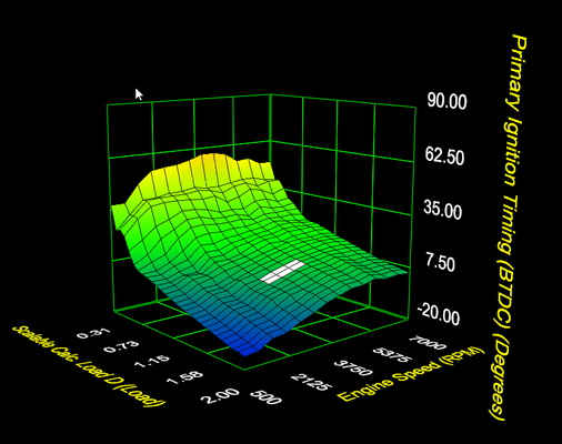
Generally speaking, a turbo-charged Direct Injection Spark Ignited (DISI) Mazda engine will run the least amount of ignition advance near peak torque and ignition advance will generally rise with engine speed. The highest cylinder pressure (detonation/misfire condition aside) is generally found where an engine can achieve peak torque so minimal ignition advance to achieve MBT or the knock threshold in that area. As engine speed increases, the piston covers more distance from time of the spark event to when peak cylinder pressure is achieved. Initiating the burn further BTDC (Before Top Dead Center) allows for consistent timing of peak cylinder pressure ATDC (After Top Dead Center) despite the increase in engine speed. This trend is normal for most internal combustion spark ignition engines. Also, as VE (Volumetric Efficiency) and/or engine load increase, the amount of ignition advance an engine needs to achieve MBT will decrease. During part-throttle operation VE and load will be both lower than at wide open throttle due to the restriction of airflow through the throttle body, so more timing advance is appropriate at part throttle than full throttle.
You should be satisfied with the ignition advance curve if while at WOT for several runs, hot ones even, the KR does not go above 2, dyno graph is smooth, and spark advance transitions through your tables in a smooth predictable curve.
5th step notes, recap:
- Ignition tables used change from "No Knock" to "Knocking" with reports of Knock Retard.
- Ignition tables used change from Low Throttle to High Throttle with open loop transition.
- The stock vehicle has several weak points which should be checked and addressed if necessary prior to tuning. Worn or inappropriate spark plugs, compressed ignition coil springs loosing tension, failing ignition coils may need to be replaced prior to tuning.
- There is a range of acceptable ignition timing advance values, but if you stray too far from what’s optimal, too little advance can be just as detrimental/damaging as too much.
- Appropriate spark plug heat range and gap varies with mechanical and tuning changes.
- The following can all reduce the knock threshold of a given setup:
- poor quality fuel
- spark plug type, gap, heat range, incorrect install
- coil pack and spring condition (lifespan on this platform is shorter than others)
- intake port and valve carbon/debris build up
- sub optimal fuel pressure
- oil and/or oil vapor in combustion chamber due to blowby, PCV system issue
- reduced battery voltage
- poor grounding
- boost leak
- inadequate intercooling
- heat soak
- Keep your vehicle in top mechanical condition and leave some margin of safety for things beyond your control.
- Make sure Intake Air Temperature (IAT) and Engine Coolant Temperature (ECT) values are stable prior to each power pull during the tuning process. The temperature difference will alter output directly, and induce various compensations within the calibration which can further alter output. You also want to allow time between runs for oil to cool for engine and turbo safety.
- Light load minor detonation from time to time is "normal." Severe detonation at high load is not. It causes uncontrolled pressure rise in the cylinder, often to extreme levels and inappropriately timed, causing damage to engine components.
- Aggressive timing advance may increase cylinder pressure beyond the capability of factory engine components, especially the connecting rods. Tune according to the expectation of reliability.
- Critical monitors to log during this step:
- Actual AFR
- Boost Air Temp.
- Calculated Load
- Coolant Temp
- Engine Speed
- Intake Temp.
- Knock Retard
- MAF Voltage
- Mass Airflow
6th – Load request, boost control
Stock MS ECU logic may not be what you’re used to. Rather than targeting boost based on boost level, these ECUs calculate and request a load value which directly relates to torque output. Boost control is merely a means to increase/decrease load by increasing and decreasing airflow. For example, if you request the same load in 1st and 5th gears, the ECU may employ significantly different wastegate duty cycles and boost levels to achieve similar calculated load and torque output.
The ECU will use the lowest torque target applicable to current engine conditions. It will check and compare values from these three groups of tables to do so:
- Throttle – Req. Load – 1-6 Gear (Norm or High BAT)
- Throttle – Requested Load – Baro vs. RPM
- Throttle – Requested Load A-C
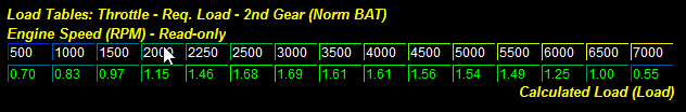
This logic allows several different strategies to be used. If you wish to simplify the tuning process, you can set some of the tables to very high values; this way the values in the remaining tables would always be lowest so the ECU will always use them to select the current target. Alternatively you can set some tables to intercede under specific conditions, while relying on the other tables most of the time. Any combination of the three can be used as you see fit, again with the understanding the lowest value that applies to current conditions will always be used.
For example, you can set the A-C and Baro vs. RPM tables to higher values and allow the gear specific ones to be used unless uncommon conditions are present.
Since this engine is turbocharged, the boost level is the main variable used to increase/decrease torque. When you increase your load target for a particular gear, you will see the ECU uses more Wastegate Duty Cycle (%) in order to increase load. If you are overshooting boost levels you feel are appropriate, you can decrease your load targets for the particular gear and the ECU will reduce the WGDC (Wastegate Duty Cycle) accordingly.
Wastegate duty cycle related tables have been set for the factory turbo. Upgraded turbos will require different settings to achieve desired results. Start conservative and work your way up.
Under the Wastegate Dynamics section, WG Duty Load Error Comp. (Course) and WG Duty Load Dynamics (Fine) (Load Based) are used to fine tune load control characteristics. These tables give the ECU authority to remove WGDC when an over load condition occurs, and add WGDC when an under load condition occurs. If you have changed your turbocharger or boost control solenoid, we suggest you modify these table settings in order to fine tune the boost control characteristics. Changes that affect exhaust pressure pre and post turbo can also require complimentary changes.
COBB offers an alternate boost control strategy which is boost rather than load based. If you’d like to try it, please review Addendum 1.
6th step notes, recap:
- When increasing load or boost target, remember you are operating the engine in areas you have not yet achieved. Make MAF Calibration, fueling, ignition timing adjustments as appropriate as you increase boost level.
- The lowest load request value associated with current conditions is the one targeted. This allows load request to be tuned several different ways depending on how you establish associated table settings.
- Check BAT high threshold values and set according to the safety level you deem appropriate. Remember the high BAT Requested Load Table values may be used as engine target if they become the lowest applicable values at a given moment.
- If you are increasing wastegate duty cycle manually via WGDC table, or by increasing load or boost target, but boost is not increasing, you have either achieved the active load target or you have reached the mechanical limit of your setup.
- If you are having a small boost spike you may need to decrease requested load a few hundred RPM prior to the over load/boost event to give the boost control system a better chance of managing pressure.
- Critical monitors to log during this step: (check Baro. Pressure once if conditions aren't changing significantly during this process, then remove from list to improve sampling rate)
- Actual AFR
- Boost
- Boost Air Temp.
- Calculated Load
- Coolant Temp
- Engine Speed
- HPFP Actual Press.
- HPFP Desired Press.
- Intake Temp.
- Knock Retard
- Long Term FT
- MAF Voltage
- Mass Airflow
- Wastegate Duty
7th – Modification of throttle table settings for part throttle and WOT controls
APP Translation tables represent how the Accelerator Pedal Position (APP) values are reported to the ECU on a per gear basis. The x-axis values are APP read only values related to APP senor output and the cell data is the reported APP value used by the ECU for throttle control. The stock values work very well. If you modify these values, remember unintended acceleration and other dangerous consequences are possible. This is at your own risk. Be very careful. We highly suggest you drive the vehicle and data log APP and TPS values on a dyno to get a better idea of how this vehicle drives after making changes.
The three DBW Throttle tables define the throttle duty cycles as a function of engine speed and calculated engine load, and thus requested torque. Each table is referenced by the Engine RPM on the x-axis and by the calculated engine load on the y-axis. Table values are the throttle duty cycle the torque targeting system will drive the electronic throttle body in an attempt to target the associated torque. Higher values mean more duty cycle, lower values mean less duty cycle. These tables most directly affect how the throttle system works during part throttle and WOT conditions. A value of 80% throttle duty cycle represents the maximum amount the electronic throttle body can be driven so we do not suggest targetting 100%.
7th step recap:
- Throttle controls can be effectively used to help manage the torque output of the engine. This includes limiting torque as the engine approaches the rev limit to help prevent overrun (over rev) conditions.
- Switching and blending functions are used which may make transitions between DBW tables less obvious.
- The three DBW tables do not share all values.
- Critical monitors to log during this step:
- Accel. Pedal Position
- Boost
- Boost Air Temp.
- Calculated Load
- Coolant Temp
- Engine Speed
- Knock Retard
- Mass Airflow
- Throttle Duty Cyc
- Throttle Duty Desired
- Throttle Position
- Wastegate Duty
8th – VVT intake cam advance, advanced calibrations
You will need to employ a load-based chassis dyno in order to determine optimal VVT settings. Start with the OTS calibration VVT settings and test changes from there. A 5 degree change per test is reasonable. To save time you can create two alternate files, one with +5 degrees VVT, and one with -5 degrees VVT. Run each of these calibrations a few times at WOT to see if any engine speed/calculated load areas benefit from your change. If torque output increases, modify your calibration in that area to use the improved VVT settings. Please take into account modifying VVT will also modify when the fuel is injected which can create other efficiencies/deficiencies. Even though VE may increase with a new VVT setting, the improvement may be offset by the change in injection timing. Keep in mind piston to valve contact may occur if a value is excessive, or if an aftermarket camshaft is fitted without appropriate re calibration of this table.
When running a balance shaft delete kit, increasing idle speed is often helpful to achieve desirable idle quality.
If your engine is stock, the factory VE (Volumetric Efficiency) table can generally be left alone. However, if you install aftermarket camshafts, for example, VE of the engine can be affected dramatically. The Engine Volumetric Efficiency (VE) table should be adjusted accordingly. In order to do so accurately, MAF scaling should be completed before the engine is altered. By doing this you can later make the internal engine change, continue using those MAF scaling values, and only adjust the VE table. This is far less confusing than trying to account for MAF and engine VE changes at the same time.
Shift Control Tables affect ignition timing compensations and limits as well as fuel compensations associated with clutch in and out events during shifts. Some calibrators find adjusting these values reduces throttle hang and other less than ideal behaviors.
If you feel your setup or strategy would benefit from altering ignition advance corrections based on boost air temperature and coolant temperature, those tables have been exposed as well. Keep in mind the percent used table can affect the result ignition correction dramatically.
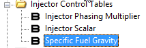
Injector Control Tables allow you to alter scaling of injector flow rate, global injection timing/phasing and fuel specific gravity.
- While most users have not replaced the factory injectors, the scaling function may be useful for those running e85 fuel.
- Injection timing changes can improve combustion efficiency. Mazda likely spent a lot of time optimizing this, but if you feel you know better we've given you the ability to phase it globally.
- Specific gravity relates to the density of the fuel, and density affects mass flow vs. volume flow. If you switch fuels and flow the same volume of fuel through the injectors, but the new fuel is more dense, your fuel mass flow increases. This alters the result air/fuel mass ratio. To avoid this you can update the Specific Fuel Gravity value. E0 reference fuel's specific gravity is .742 kg/m^3 which you will find is very close to the .74 value used in the stock calibration. E10 (10% ethanol gasoline blend) reference fuel's specific gravity is .7496. Summer blend E85 (~85% ethanol) is about .785. Keep in mind the contents and mixture in pump gas and e85 are rather variable, even from the same station so specific gravity of the fuel pumped at any moment will vary. Specific gravity is also temperature dependent. In short, don't chase your tail. The values we've provided will get you in the appropriate ballpark.
- During VVT tuning, be sure to log Calculated Load, Engine Speed, and Knock Retard.
We hope this Accesstuner Tuning Guide has been helpful! Please e-mail us with any criticism or comments so we can continue to improve it.
Addendum 1 – Boost control guide for pressure-based boost tuning (BT)
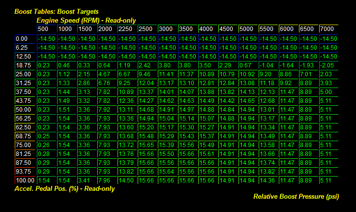
When the “Use Boost Based Dynamics (Boost Control)” toggle is checked, the boost control strategy changes. The ECU will target the boost level set in the Boost Targets table rather than operating at a boost level necessary to achieve the current target load value. The WG Duty Load Dynamics (Fine) and WG Duty Baro Error Comp. (Fine) tables are not referenced in this mode. Instead the WG Duty Boost Error Comp. (Fine) table is referenced. To clarify, the WG Duty Load Error Comp. (course) table is active in either mode, though it is generally zeroed out.
Start by setting your WGDC table to zero and Boost Targets tables to conservative values. The ECU will take the result of the Boost Targets table and compare it to the current boost level measured by the MAP sensor. If actual boost is greater than target boost, the ECU will reduce the WGDC to attempt to lower actual boost to match target boost. The opposite is true if actual boost is less than target boost. To do so, wastegate dynamics are employed. Some tables are noted as boost based, others load based.
The stock boost control system adjusts WGDC at a very rapid rate and is capable of properly controlling turbo boost as long as the WG Duty Cycle and Wastegate Dynamics values are appropriate.
Depending on how your boost control system is mechanically set up, you may need to modify other boost related tables as well. We will go over this in greater detail below.
The following screen shots and logic descriptions explain how the boost control system functions while using this COBB custom feature.
1st - The ECU logic “looks up” the Boost Target based on RPM and Throttle Position.
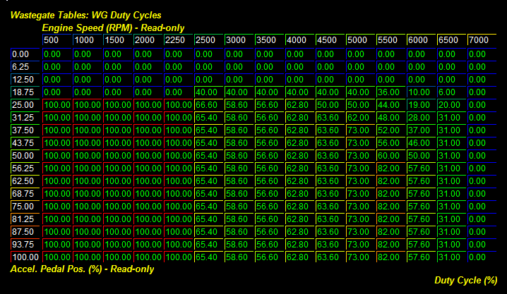
2nd - The ECU “looks up” the base WG Duty Cycle values in reference to Engine Speed and Throttle Position. The ECU will then drive the boost control solenoid based on the duty cycle noted.
3rd – The ECU takes readings from the MAP sensor at high frequency and measures the Delta Δ (difference between) Boost Target and the actual measured Boost at the current Engine Speed and Throttle Position.
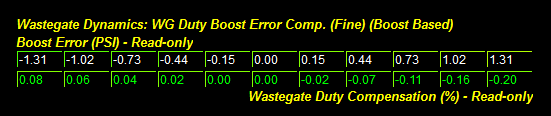
4th - The ECU “looks up” compensatory Boost Error Comp. values and modifies the WGDC in an attempt to achieve the boost target.
The values in the WG Duty Boost Error Comp. (Fine) (Boost Based) and WG Duty Load Error Comp. (Course) tables give the ECU the authority to modify the WGDC during over boost and under boost target conditions. The values to the right of 0 load error give the ECU the authority to reduce WGDC when boost is over target. The values on the left side of 0 boost/load error give the ECU the authority to increase the WGDC when under target.Be sure you don't enter opposite values which could cause Wastegate Dynamics to make an over or under boost condition worse rather than better. If you are getting significant boost oscillations, you may need to fine tune the values in this table or you may need to recalibrate the WG Duty Cycles table.
In order to achieve more consistent boost control, it is essential the individual "Throttle - Req. Load (Norm BAT)" tables fall within .05 of actual observed Calculated Load if the WG Duty Load Error Comp. (Course) table is not set to zero. To simplify things, setting the (Load) based WGDC correction tables to 0 will allow for boost based wastegate dynamics only.
If you are having a small boost spike you may need to decrease Target Boost and/or WGDC a few hundred RPM prior to the over boosting event to give the system a better chance of maintaining control.
Copyright 2025 © COBB Tuning Products LLC. All Rights Reserved. | www.cobbtuning.com