312550 AND 312560 - Subaru Flex Fuel Ethanol Sensor Kit Installation Instructions

312550 / 312560 – Subaru Flex Fuel Ethanol Sensor Kit
WRX 2006-07, STi 2004-2006, STi 2007, Forester XT 2005 - 2008 (Brackets, Ethanol Sensor, Fittings, Flex Fuel Module)
Congratulations on your purchase of the COBB Tuning Flex Fuel kit! The following instructions will assist you through the installation process. Please read them BEFORE beginning the install to familiarize yourself with the steps and tools needed. If you feel you cannot properly perform this installation, we HIGHLY recommend you take the vehicle to a qualified and experienced automotive technician.
IMPORTANT! Installing this kit will require custom tuning or utilizing an appropriate Stage Power Package map if you have a matching mechanical configuration. Please consult with COBB or an authorized ProTuner in your area.
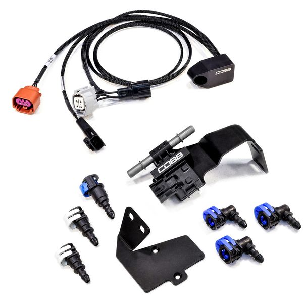
Part List
- 1 x Flex Fuel Module
- 1 x Flex Fuel Sensor
- 2 x Flex Fuel Sensor Bracket
- 2 x 5/16" straight fuel line connector
- 1 x 5/16" 90* fuel line connector
- 2 x 3/8" 90* fuel line connector
- 1 x 3/8" → 5/16" straight fuel line connector
Tools Needed
- 5/16" or 8mm Fuel Line Disconnect Tool (Available at Professional Tool Sources)
- Flat Head Screwdriver
- 10mm Wrench
- 12mm Wrench
- 10mm Socket
- 12mm Socket
- Ratchet
- Pliers
- Diagonal Cutters or Scissors; (Hose Cutting tools suggested for straightest cuts)
- Safety Glasses
- Rags
- Silicone Spray or Similar
Important! Before removing your fuel line, make sure to discharge existing fuel pressure from the system. Failure to do so can result in fire, property damage, and/or death!
Removal of Existing Fuel Lines
- With the car parked in a flat level area open the door on the passenger's side.
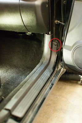
- Remove the passenger side sill plactic trip and kick panel by removing the screwed in connector in the foot well and the single push pin near the door hinge.
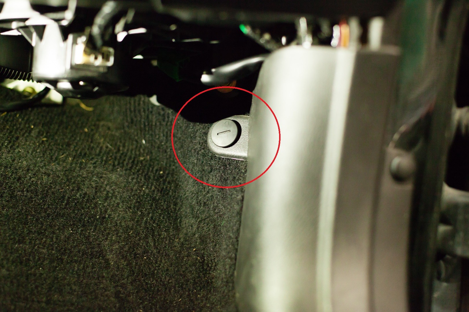
- Once that is done, lift the panel straight up then towards the rear of the car to remove it.
- Now, start up the car and allow it to idle.
- With the car idling, disconnect the green → white 4-in connector (this is not the test mode connectors which are green → green)
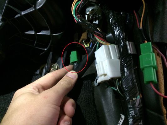
- Now allow the car to run until it stumbles and dies, then turn the key off and remove it from the ignition.
- Now to relieve the last bit of pressure, remove the gas cap from the tank
- With all that done, go ahead and undo the negative terminal of the battery.
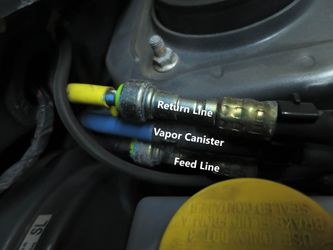
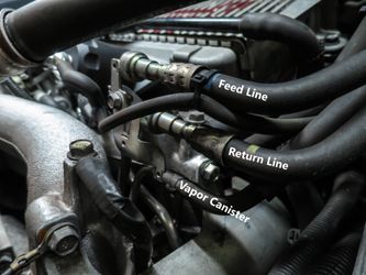
With the power unhooked go ahead and remove the stock feed and return lines. You'll need to use a 5/16 fuel line quick-disconnect tool, simply press it in the end to release the lines. While not strictly necessary, removing the return line can give you more room to more easily access the feed line.
The color of the sheathing on the hard line at the firewall is not consistent across all year/models.

Installation of COBB Flex Fuel Sensor 04-05 STI
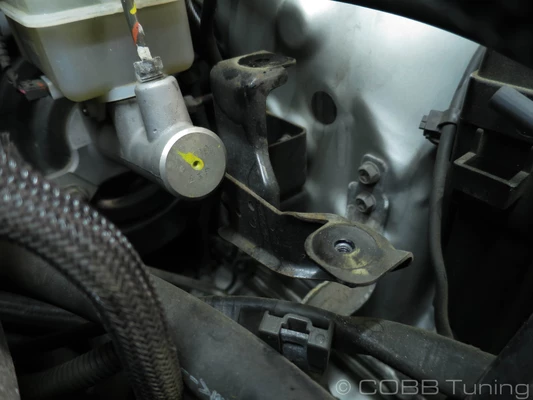
- Unbolt the flex fuel sensor from the existing bracket using a 2.5mm Allen Head Wrench
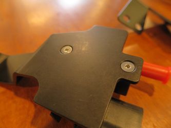
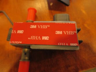
- Grab the other bracket and install the sensor onto that one instead. Making certain to unpeel the double sided tape so that it sticks when installing (you may want to test fit first as there are two applicable orientations for the sensor and one may work better for your particular car than another.)
- Remove the bolts holding the fuel line bracket to the strut tower and slip the assembly in behind it, rebolting everything down afterward.
.png?version=1&modificationDate=1579725552758&cacheVersion=1&api=v2&width=333&height=250)
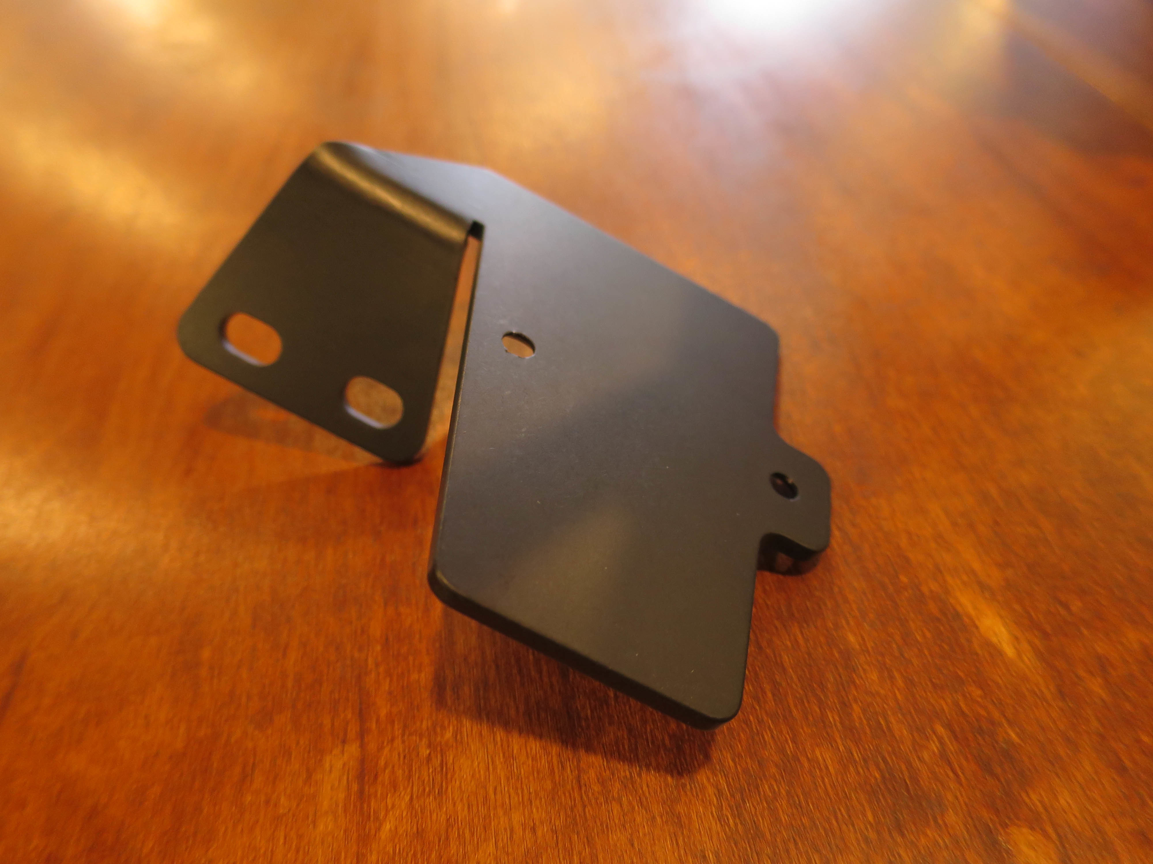
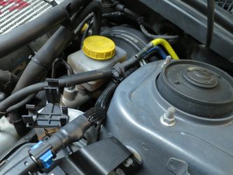
Installation of COBB Flex Fuel Sensor All Other Models
- Unbolt the flex fuel sensor from the bracket using a 2.5mm Allen Head Wrench
- Peel off double sided tape cover and reinstall
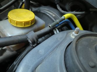
- Unbolt the air pump from the driver's side strut tower using a 10mm socket.
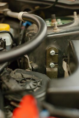
- Bolt the COBB Flex Fuel Sensor in the same location.

Notes on Flex Fuel Kit Hose Installation.
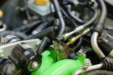
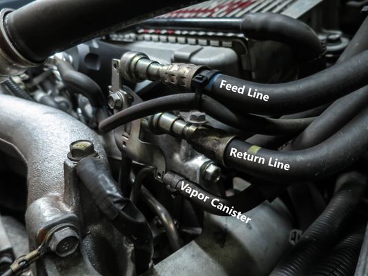
The COBB Flex Fuel Sensor installs between the manifold side fuel line connector and the regulator. In our example we're still using the factory regulator so we'll be installing the sensor on our feed line. Our Flex Fuel Sensor and/or Fuel Pressure sensor do not restrict fuel flow and will not cause any hindrances. It's also mandatory that you install either sensor pre-regulator to ensure accurate readings. The flow of fuel is as such:
- Fuel tank → firewall side fuel hard line connection point → (INSTALL SENSOR(S) HERE) → intake manifold side fuel hard line connection point → fuel rail (OEM fuel pressure regulator) → combustion → manifold side fuel hard line connection point → firewall side fuel hard line connection point → fuel tank
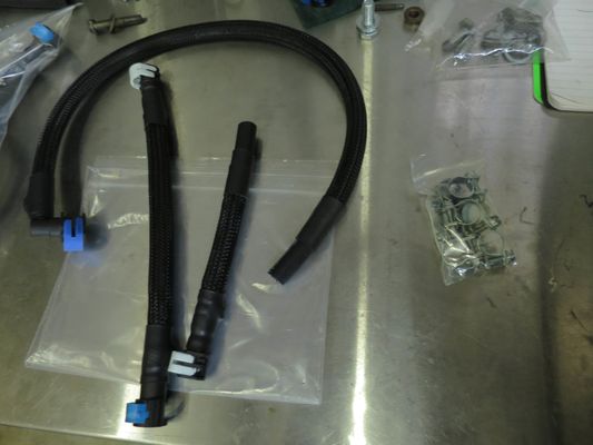
We have included variety of fuel line connectors for a variety of applications, all of the factory fuel line connections are 5/16" while the connections on the ethanol content sensor are 3/8". The stock fuel lines have dampers built in however those are no longer necessary as the rubber line itself provides a dampening cushion unlike the relatively hard plastic of the old fuel lines.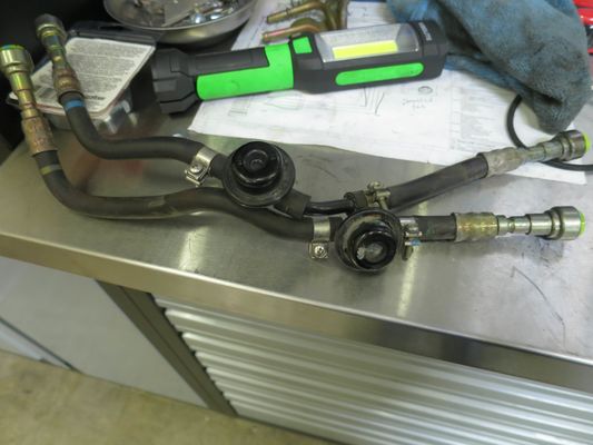
Hose Installation
It is absolutely critical that hoses are routed away from heat sources and protected from rubbing on anything. It's usually best if they're held down by zip ties or the factory brackets as damage to the lines can cause a leak or fire. In many cases adding some type of sheathing can add to the longevity of the hoses. Make sure all of the lines have some slack to allow for engine movement to avoid putting undue strain on the lines.

- Before doing anything make sure to use super lube or another silicon grease on all of the hard lines and fittings to prevent damage to the o-rings that help seal everything.
Start out by adding your connectors loosely to each end of the line you're doing at that time, then measure the distance, sometimes using a piece of string can help get an idea of routing, but it's usually best to use it with an actual piece of hose to get an idea of how far it can be bent without kinking and how it will fit with everything else. The white connectors are 5/16" for the stock fuel lines and the blue connectors are 3/8" for the Ethanol Content Sensor.

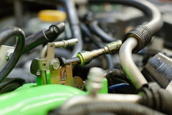
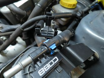
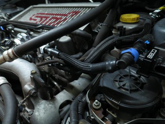
- Using a straight 5/16" on the firewall for the feed line, route and trim a hose that fits up to a straight 3/8" fitting on the Ethanol Content Sensor. Make sure to test fit before adding clamps or cleaning things up with sheathing or heat shrink.
- Now that the difficult to reach firewall end connection is taken care of, we can go ahead and reinstall the factory return line from the top fitting on the firewall, to the middle fitting on the engine.
- If Installing COBB Fuel Pressure Sensor Kit at the same time do this step, if not skip and move on to step 6
If you're putting in a fuel pressure sensor you'll either want to install it using this reference as a guide of where it needs to be.Subaru Fuel Pressure Sensor Kit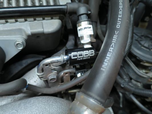
- Using a 90° 3/8 fitting on the ethanol content sensor, route the line over to a 5/16" fitting on the manifold/pressure sensor.
- Make sure all the clips are secured and the lines are seated properly, then turn the key to the on position to allow the system to pressurize. Having a friend to keep an eye on the lines while turning the car on can be a big help and can prevent too much of a mess being made. If no leaks are found, you should be good to move on to the next step!
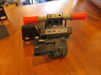
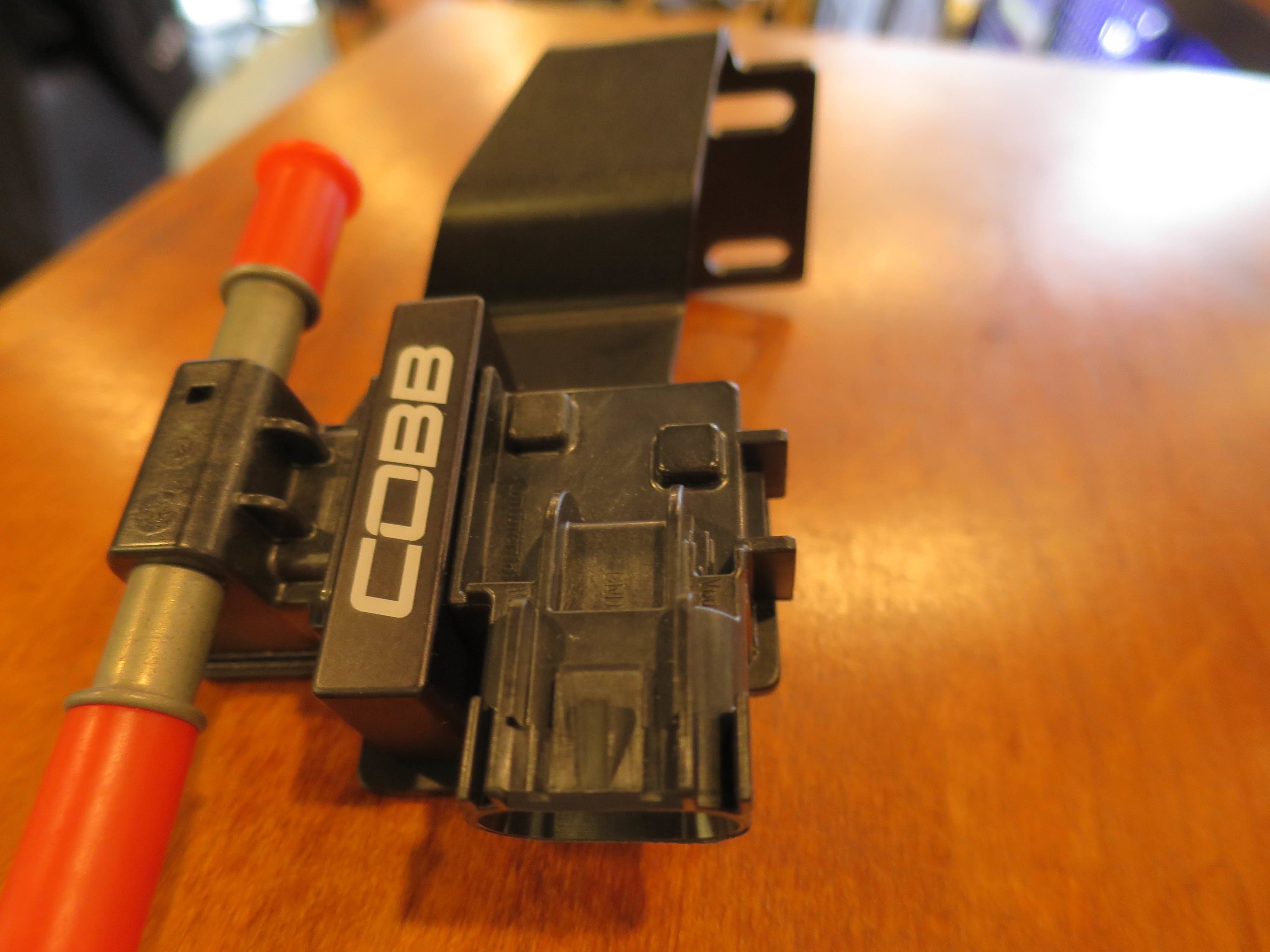
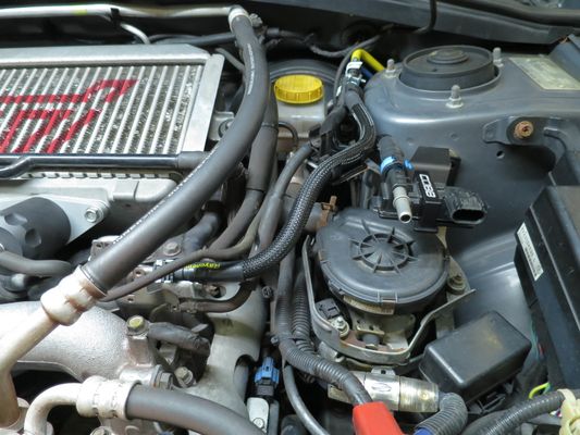
Installation of COBB Flex Fuel Module
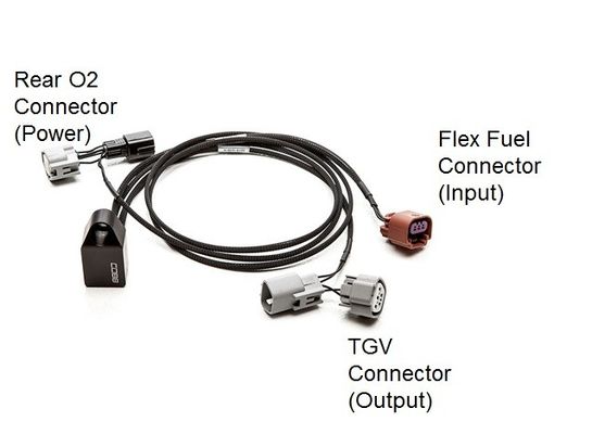
The COBB Flex Fuel Module is designed to be bolted to the inter-cooler support bracket and plugged into the COBB Ethanol Sensor, in-line with the factory Rear O2 sensor and Tumble Generator Valve (TGV).
The Rear O2 connector obtains 12V power, and does not alter the O2 sensor signal going to the ECU. The TGV connection allows the motor signals to pass through for those still using the factory TGV's, however the feedback normally used to check TGV position is used to transmit Ethanol content data to the ECU (Engine Control Unit).
Mounting location may vary by customer/ installer preference, however it is recommended to seal any un-used connections from water intrusion, ideally by using the proper connector mate and using plugs to seal the mating connector.
- Bolt the Flex Fuel module to the inter-cooler support bracket using the included bolt. Straighten the cables so that they aren't crossed over each other.
When plugging in connectors, make sure they are fully seated with a "click".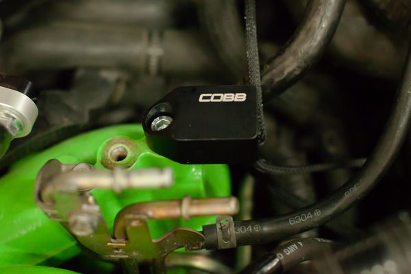
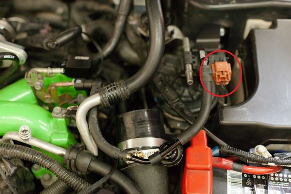
- Pass the Flex Fuel Connector through the factory hoses and wiring harnesses and plug it into the Ethanol sensor. Ensure there is no strain on the connector, wiring, or the module.
- Pass the TGV Connector through the factory hoses and harnesses to the TGV position sensor on the driver's side of the vehicle toward the rear of the engine. Especially if on a lift, you may find this easier to do from the bottom of the vehicle where there's a clear path to the TGV. Ensure there is no strain on the TGV connector, wiring, or the module.

- Route the Rear O2 Connector to the bottom of the engine bay, then suitably raise and support the vehicle. Never work on a vehicle supported by a jack alone.
- Connect the Rear O2 Connector between the factory O2 sensor harness and the O2 Sensor connector.
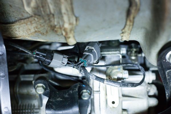
- The O2 connector harness has extra length to work on a variety of vehicle configurations. Using the included zip-ties, secure the harness to the metal lines on the underside of the vehicle and in the engine bay. Ensure that the harness will not make contact with moving parts like the steering column, exhaust parts, and has sufficient slack between the engine and lines as well as lines and harness so that there is no strain as the engine moves.
Final Assembly
- Re-install the battery, ensuring that it does NOT make contact with the new fuel hose, as the sensor bracket is designed to press against the fuse box, but NOT make contact with the battery.
- Reconnect the positive terminal, and cover with the factory guard to reduce the risk of short circuiting the battery. In case you missed the step above, make sure there is NO exposed fuel or rags near the car. Fumes can easily be ignited when connecting the battery.
- Reconnect the negative battery terminal and prime the fuel system by cycling the key between the "OFF" and "RUN" positions at 3-second intervals. 4 or 5 cycles will be adequate to re-pressurize the system. CAREFULLY INSPECT FOR LEAKS AND IMMEDIATELY CORRECT IF ANY ARE FOUND!
- Prime (Turn the key but do not start the engine until the fuel pump stops), then start the vehicle and again inspect for any leaking or abnormalities. Halt immediately if any fuel leaks or other issues are found!
- Installation of the Cobb Flex Fuel kit is now complete! We recommend inspecting for any signs of leaking or component deterioration periodically for safety and performance purposes. Enjoy your new COBB Flex Fuel Kit!
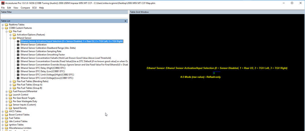
Calibration Data
Ethanol Sensor Input Selection = TGV Left
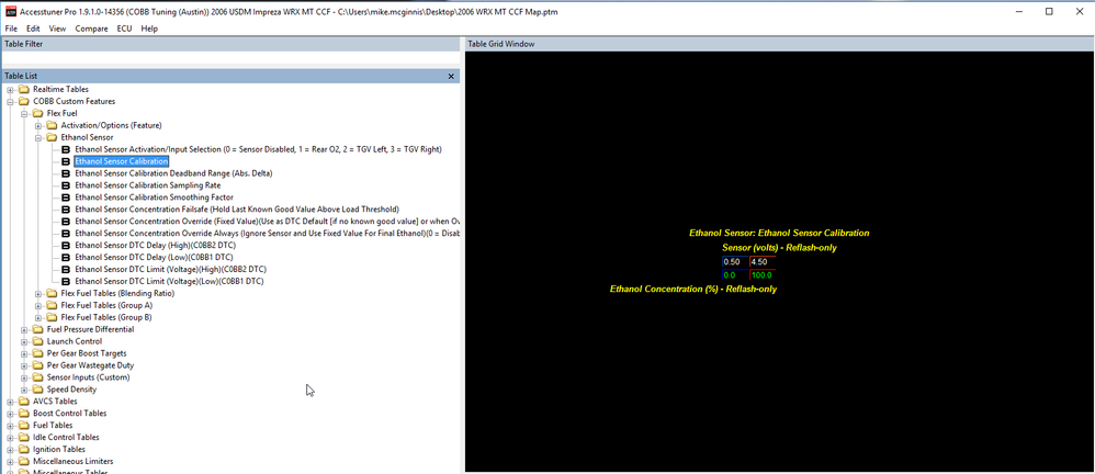
Sensor calibration:
0.5 V = 0% Ethanol
4.5 V = 100% Ethanol
Links
COBB Product Install Instructions for Subaru Vehicles
Main Installation Instruction Repository for Subaru Parts
Copyright 2024 © COBB Tuning Products LLC. All Rights Reserved. | www.cobbtuning.com