Skip to end of metadata
Go to start of metadata

You are viewing an old version of this page. View the current version.

Compare with Current View Page History

« Previous Version 8 Next »


Tuning Guide


  • 2020-2021 Macan GTS
  • 2020-2021 Macan Turbo
  • 2019-2021 Macan S


Despite slightly different engine configurations, the 95B.2 Macan vehicles all use the same ECU and same general control strategy.

  • Macan S
    • 3.0 Liter V6 with a single twin scroll turbo mounted to the top of the motor between the cylinder heads, also called a "Hot Vee" configuration for channeling the heat of the exhaust into the center of the v portion of the block.
  • Macan GTS & Turbo
    • 2.9 Liter V6 with twin turbos. Also both centrally located between the cylinder heads at the top of the motor.
    • These two vehicles are mechanically identical.  The factory difference in power rating is entirely from the calibration.

Factory Calibrations

The plot below shows the stock curves from all three Macan models.  The 3.0l motor found in the S (shown in green) is lower by comparison, however the turbocharger spools up more quickly.  These cars make torque very rapidly, but aren't as efficient at high RPM.  As such any attempts to increase power and hold out boost at higher RPM will typically just generate additional heat without increasing power.


In comparison, the GTS (Red) and Turbo (Blue) can move significantly more air at high rpm and will overall make more power.  This additional airflow however results in a slightly later spool up compared to the S.  As you can see by the relatively similar lines below 5000RPM, the calibration difference between the GTS and Turbo is a simple calibration change resulting in additional power at high RPM.


Calibration Results

Keep in mind tha the best and fastest way to evaluate your own calibration strategy is going to be to look at the COBB OTS maps as a starting point.

Macan S 95B.2 Map Notes


The ECU as a System

Porsche calibrations, regardless of ECU variants will require torque limits and targets to be adjusted (typically raised) to meat your goals.  At the end of the day being able to adjust those tables and have everything work in concert is your goal.  Within the range of Porsche vehicles there are a variety of tuning strategies which make achieving this goal a different process.  This tends to mean that if you are an expert with 991.2 turbo 911 cars, everything will look somewhat familiar, but you'll still face a small learning curve in terms of exactly which tables require changing.

These ECUs have very well modeled tables looking for a fairly consistent level of vehicle operation.  This means that in order to produce a finished calibration, you'll need to make a large range of changes.  It's not possible to only change one parameter at a time and expect to make sustainable power.  As an example, if you are working to optimize factory ignition timing or fuel, you will not see an increase of power in the presence of the factory torque limits and targets.  In order to make power and tune the car the best way to start is to push the limits out of the way (but to a safe limit) in order to keep the vehicles behavior and targets consistent with the power you're targeting for your powertrain and fuel.

In order to preserve the balance of driveability and speed that the factory clearly worked so hard to achieve, it's recommended to minimize the table changes you do make.  This seems counter intuitive when we just told you that you need to adjust more tables than you think, but if there is a change you feel may not be important or related to the desired behavior of the vehicle we recommend returning it to stock.  This makes sure that the character of the vehicle can be preserved, and any undesireable effects from the complex interrelation between tables doesn't cause any issues.




COBB OTS Mapping Changes Explained

Torque Targets

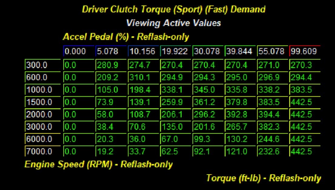
Driver Torque Demand (Accelerator Pedal and Clutch)

There are several tables within the Torque Control folder that control and describe the relationship between the accelerator pedal position and the torque the engine gives in response.  Because the Accelerator pedal acts as a torque selector for the driver and is one of the few ways the driver communicates with the engine, it can have a huge impact on the driveability/character of the vehicle.  Do you want a car that with the slightest input takes off?  Or do you want a mild mannered daily driver that can but the hurt on that prius in the next lane?

These tables all function primarily as a torque request, however if they aren't raised high enough to hit the torque the vehicle is producting, it can also functionally act as a limit on the torque requests.  This is because if your torque request maxes out at 400, but your car thinks it can hit 500, it will see that you're only asking for 400 and respond accordingly.

In our calibrations we raised the higher demand sections (higher Rpm/Accelerator pedal %) to a higher torque request in order to hit the increased power we were targeting.  In order to maintain driveability we left the lower sections stock.

In areas of RPM / pedal position the vehicle will find itself sitting in or transitioning through frequently (cruise/around town part throttle driving) it's a good idea to make sure there are no abrupt transitions, as that can lead to the feeling of surging or disproportional acceleration while trying to maintain a consistent speed.


Torque Limits

The factory ECU is constantly calculating torque output in order to deliver exactly the output that Porsche designated by using a variety of torque limits.  The purpose behind that is in order to create a calibration that performs the same in all conditions.  This means regardless of temperature, ambient pressure or other variables it would go after the same amount of power.  Our goal is to remove or adjsut these limits in order to produce our new higher power output.


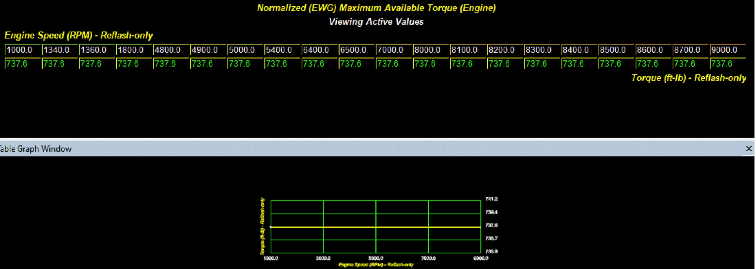
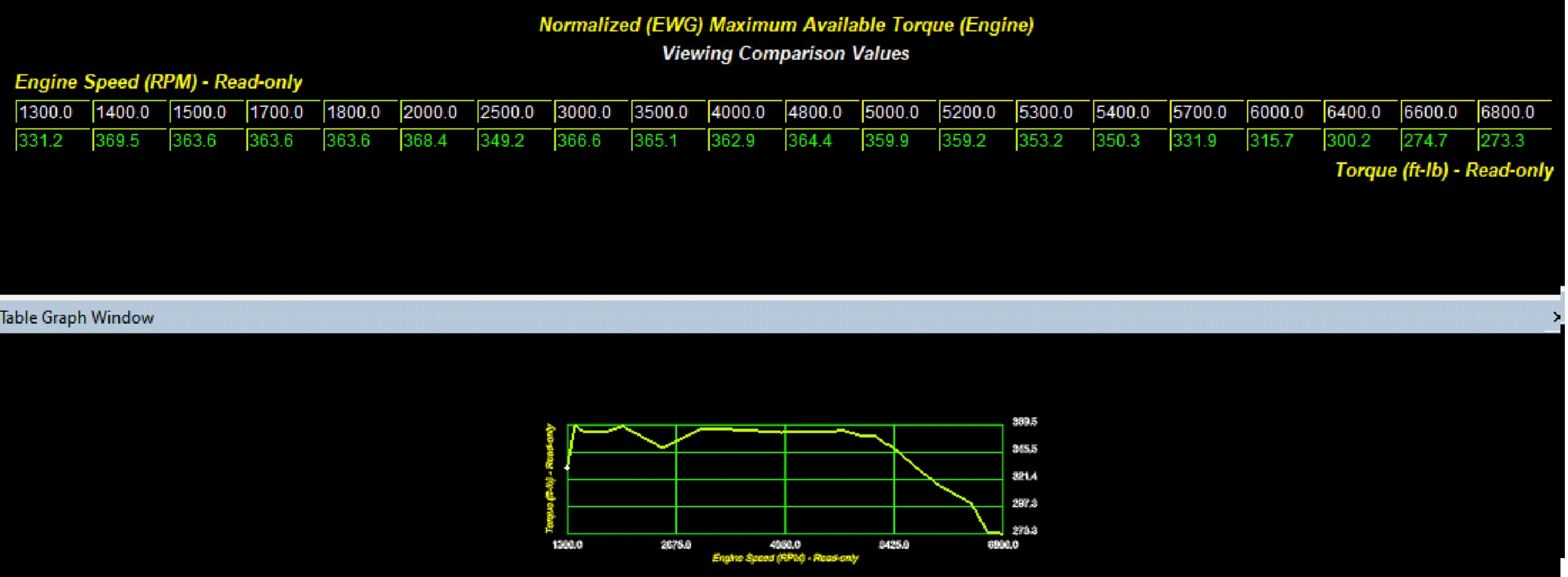
Within the Torque Control folder all of the tables that list Maximum Available Torque in their name function as limits.  For the Macan S we raised all of these tables to their maximum values and utilise other functions such as torque requests to limit the torque created.  We found that for the most part this was a requirement to make additional power on the S.  For the other Macan models we were able to use these tables as targets in order to manage our power output.

There are additional tables called the Engine Speed Threshold for Valid Actual Engine Torque, functionally these tables set the timer for how frequently the ECU looks at the torque output.  In effect by increasing the timer delays and adjusting the RPM activation points you can choose when (if at all) the computer is actually referencing the torque limits.

How you choose to use these tables is up to you and the goals for your calibration.


Load Control

For this collection of vehicles, adjusting the relative load request and limits is the easiest way to get them to target additional airfow and boost and thus achieve a higher amount of torque.

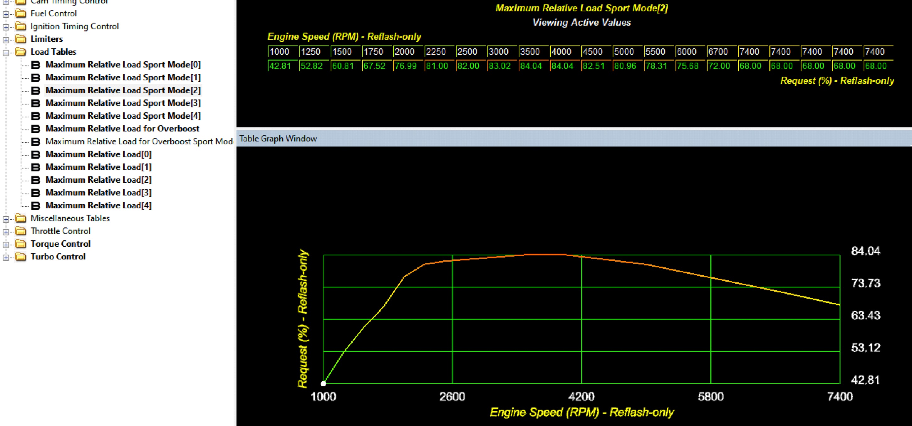
Within the Load Tables folder there are several tables that describe the Maximum Load.  These tables function as targets and limits.  Relative load becomesthe cylinder fill target.  The cylinder fill target then creates the airflow request which is translated into boost request and torque.  If your cylinder filling, boost, and torque limits are all set accordingly, adjusting these tables will allow you to make additional load and power.


In a nutshell the process works like this

Accelerator Pedal (driver Request) and RPM → Desired Torque→ Relative Load Request→ Cylinder FIlling→ Airflow/Boost

Keep in mind that this will be limited by your set limits such as:

  • Maximum Load
  • Maximum Torque
  • Temperature
  • Ambient Pressure
  • Boost Pressure
  • Compressor Ratio
  • Egt
  • etc.


One thing that can get confusing is that some phrases are used interchangeably in the operation of the ECU (from the factory)

Relative Load % and Cylinder Filling

Torque Percentage and Relative Load


Relative Load

Among the relatiave load tables there are some related to different drive modes.  For all COBB OTS maps we chose to keep these the same through all drive modes.


Some Relative Load tables are all zeros from the factory.  This is an indication that the tables are not referenced by the factory calibration and logic.  As such they should be left 0.

Because Porsche uses different operating systems among other changes between the same vehicle even, you cannot simply copy from one calibration to another.  You'll need to make base maps for every ROM ID and OS preserving the tables that are left at 0 and using the same ones the ROM references.


Relative Load And Cylinder Filling

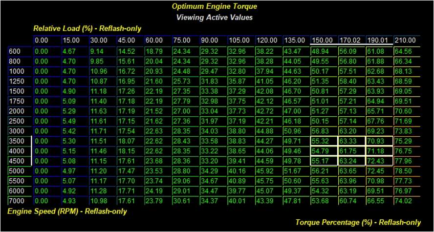
The relationship of load and cylinder fill is fairly similar to the relationship between torque and airflow on the other porsche platforms as well as VW and Audi vehicles.  In this case the Maximum Relative Load table references the Optimum Engine Torque table in order to determine a Target Filling


In the graph to the right you can see that a requested load value of ~62 at 4000 RPM< results in a target fill of 174.  This relationship is determined by the Optimum Engine Torque table.


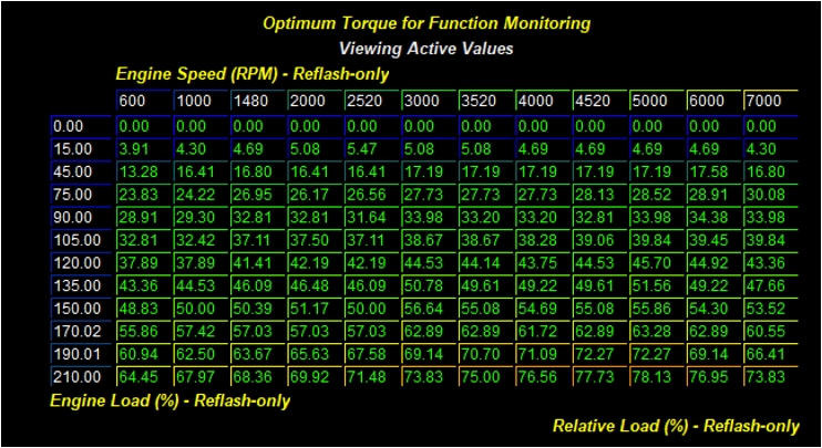
The other way that Porsche described the relationship between Relative Load% (Cylinder Filling/Airflow) is in the Optimum Torque for Monitoring Engine Function table.  There may be one or more of these tables depending on the rom.  This table is the same data as the Optimum Engine Torque table above, but the Z Axis (Relative Load%) is now the Y- Axis and Relative Load is now the Z Data.  Just like with the Torque and airflow tables on other vehicles, if you change one of these tables you will need to change them both in order to ensure proper function.


Why Change the Relationship Between Cylinder FIll and Relative Load?  In some cases it might be desireable to increase the cylinder fill for the given load.  This will increase power, however any deviation from factory load calculations will impact the way the vehicle drives both in engine response and transmission shifting.


Load Limiters

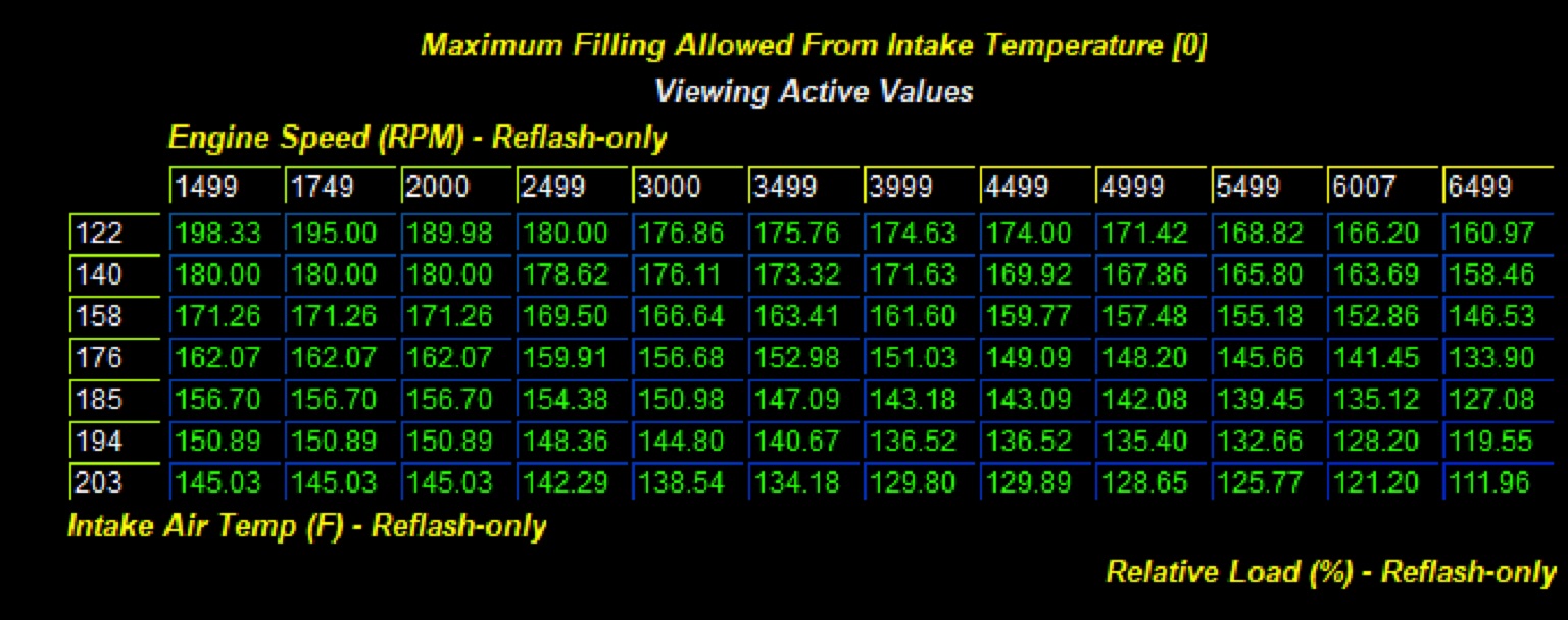
Within the Limiters folder there are a series of tables that describe Maximum Cylinder Filling Allowed from Intake Air Temperature


These tables (quite logically) adjust Relative Load % (Cylinder Filling) as intake air temperatures rise.  While they can be adjusted to reduce the reduction and keep the car producing the same into hotter conditions, keep in mind that these tables are in place to ensure stable and safe driving operation so while some change is going to be fine, there will be a point where you will potentially be compromising the size of the safety margin the vehicle is operating with.


Ignition Timing

The Ignition Timing on these vehicles is similar to may other VAG products in that it has a The stock ignition timing system works very well in response of meeting the needs of both stock operation and the increased load targets you'll typically see with tuning.  Given that this vehicle is designed to run from the factory on 93 octane it was unsurprising that we did notice some knock response under heavy load when using 91 octane fuel.  As a result timing was reduced in order to create a calibration more suitable for that fuel while still having a performance improvement.

The main ignition tables you'll need to modify are

  • Ignition Timing (Normal) 1
  • Ignition Timing (Normal) 2
  • Timing Map
  • Timing Map Variant 2

These establish the timing under most normal driving conditions based on load and RPM.  While the values in these tables aren't fully identical it's best practice to offset the tables by the same amount when making changes.  I.E. Remove/Add 1.5 degrees from the same point of the table.

The Optimum Timing table establishes the model for engine behavior and "Perfect" Timing under ideal (impossible) conditions.  These are not values you should use in the normal timing maps, nor should this table be altered for any stock motor operation.


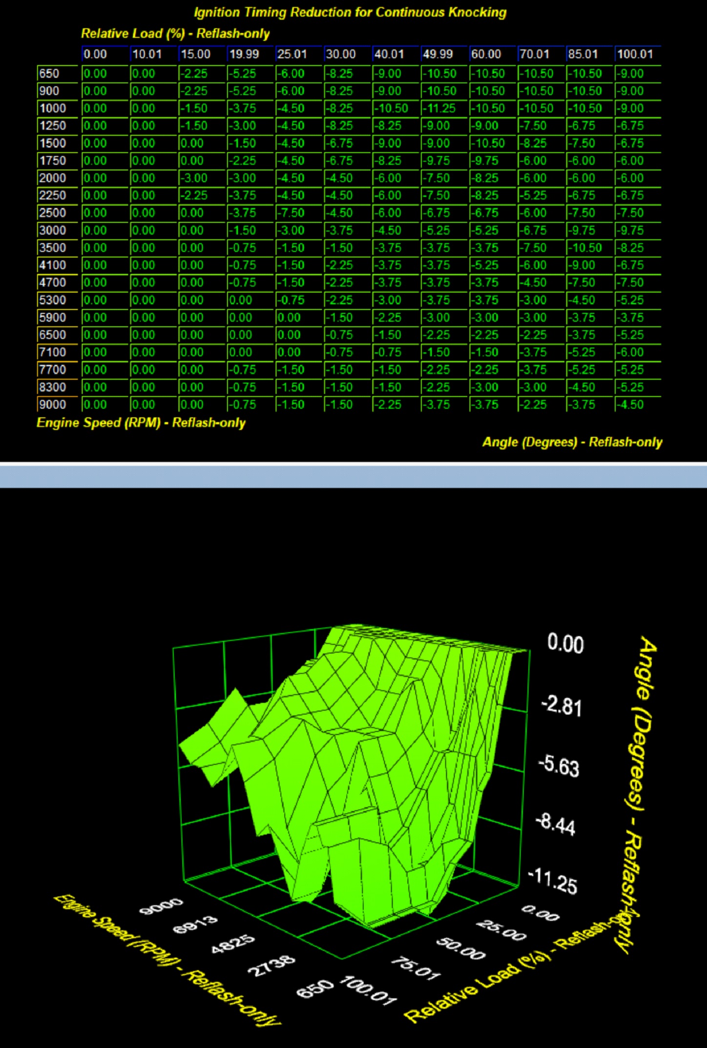
Delta Timing from Continuous Knock

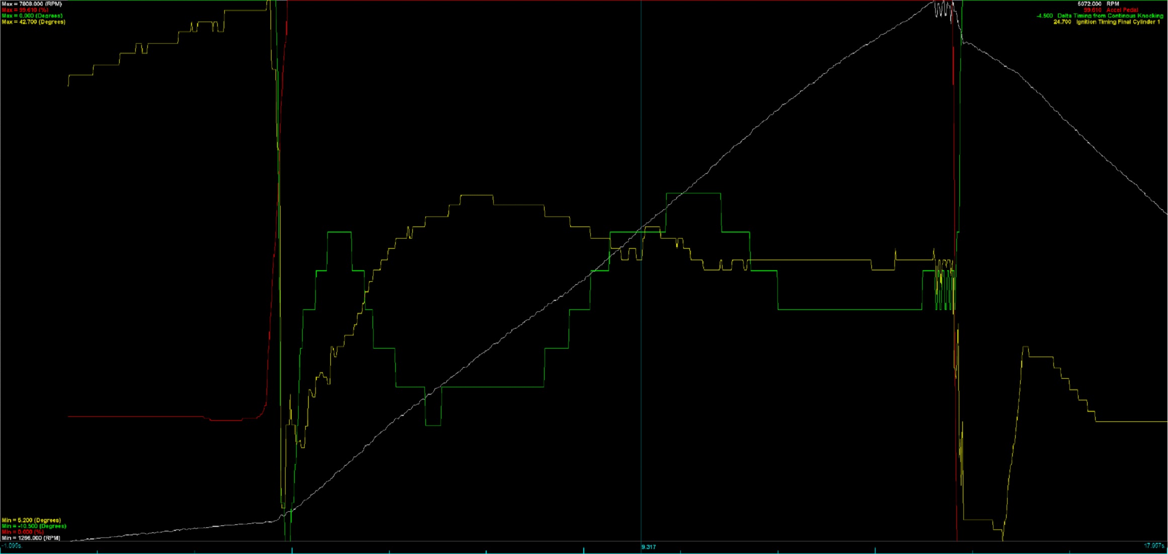
The newer operating systems used in Macan, Cayenne, and 4.0L NA Porsche applications have a new monitoring system labeled as Delta Timing from Continuous Knocking (DTCK). This table in the software acts similar to the DAM system in subaru, as it is actively adjusting the allowed ignition timing based on a learned knock response (Knock observed over time).  While thhis table is able to be modified, we recommend leaving it stock as it is a clear safety system for the car that operates properly, and shouldn't impact the ability to tune the vehicle provided the ignition timing values you target don't cause knock.

The monitor for DTCK is actually reporting the potential timing reduction that can be applied in the event that continuous knocking is recorded.  It is NOT a measure of timing actively being removed.  If you refer to the final ignition timing of any given cylinder in a datalog, you’ll see that it does not incorporate the output value from DTCK.


Fuel System

These vehicles do not have a fuel table for full load.  The only fuel control available is related to EGT control and component protection.  The ONLY time these vehicles will target something other than 1 lambda is in a effort to control EGT and protect components of the engine.

In our experience, the stock fuel tables and control systems were perfectly sufficient to make extra power and torque needed for our OTS maps.  Furthermore, using stock almost completely stock calibration strategy for low and medium load means that Porsche’s strategy to produce an emissions appropriate vehicle is preserved.  For those wishing to push these vehicles further you may need to take additional steps. The easiest way to get it to target a different fuel target is to change the conditions under which it goes into component protection mode, and use those tables to achieve your targeted behavior.


Turbo Control

All of the COBB OTS Calibrations are currrently designed for stock turbo only.  We have found that the stock turbo parameters produce excellent results.  There are some noteworthy exceptions to this and a few tables of well-defined function and high utility can be changed for better results.    Airflow control is perfectly matched to the desired airflow requested by the concert of changes throughout the calibration.

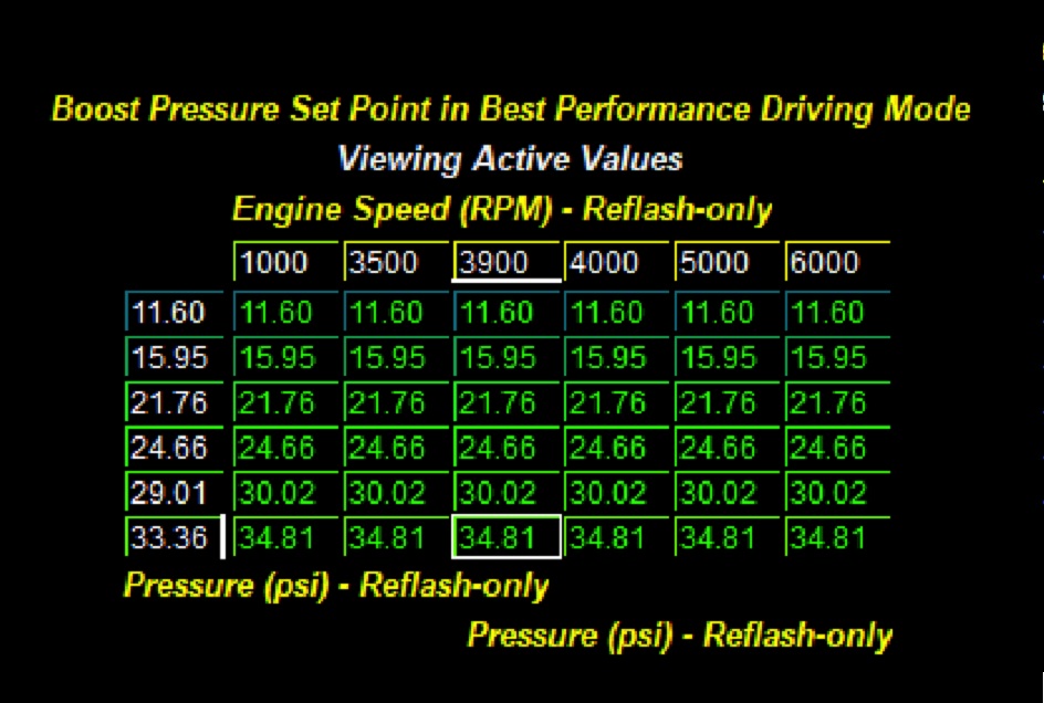
Boost Pressure Set Point in Best Performance Driving Mode
This table needs to be altered in a way that higher boost set points and their associated manifold pressure targets can be achieved.


Maximum Boost
This single 1D Value is extremely useful.  You can use this value to limit your calibration manifold pressure to a set upper limit.  This is not a harsh boost limit, the calibration will simply limit manifold pressure to this value.  This table was used in order to limit boost in both the 93 and 91 octane OTS  maps and is a highly useful tuning parameter.


  • No labels