
F150 - Raptor TCM Tuning Guide
Introduction
Getting to know the Ford Raptor TCM
Here we will go over a few of the basic details and terminologies that are specific to conventional torque-converter equipped automatic transmissions.
Commonly Used Acronyms:
|
Factory Raptor 10R80 Information (starting at page 314)
Stick Diagram:
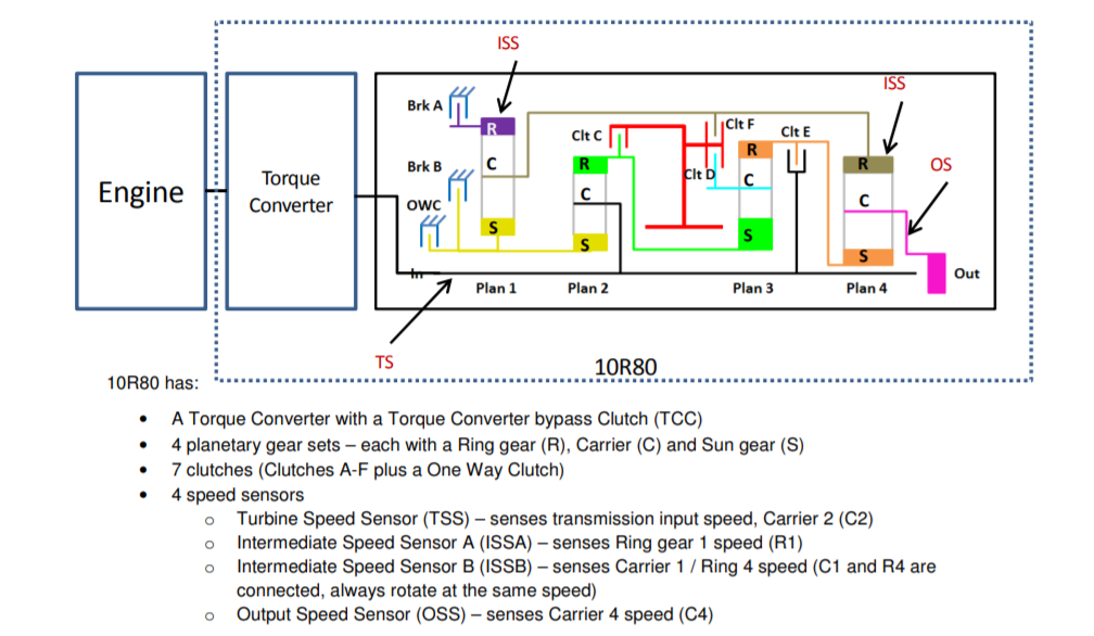
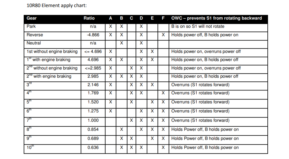
Clutch Element by Gear:
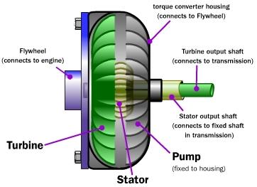
Torque Converter Nomenclature:
Accessport Firmware Version Required
- AP3-FOR-005: 1.7.3.0-19470
Accesstuner Pro Required
- 3.0.0+19485.16796
| Panel | |
|---|---|
Table of Contents
|
2019 Calibration Consolidation:
All of our OTS TCM maps for ’17-’19 Raptors have been configured to use a factory transmission calibration from a ’19 Raptor as a base. Ford has spent considerable time and effort to improve the operation of the 10R80, and we have chosen to inherit those changes as the foundation for our performance tunes. This also means that when viewing "stock" data in ATP for a 2017 or 2018, the 2019 calibration data will be shown. Highlights of this change is drastically improved shifting behavior in Sport drive mode, including the notoriously harsh 4-5 shift.
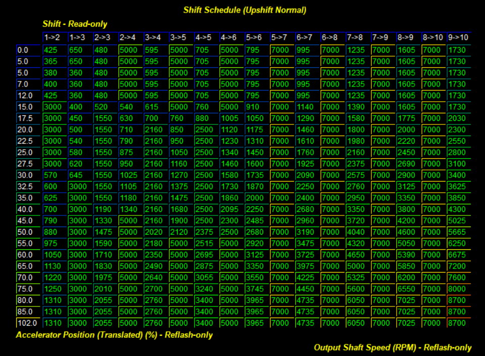
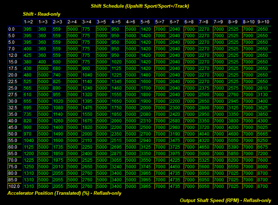
Shift Schedules:
All 10R80 shift schedule tables are presented using APP and engine RPM as axes, and transmission output shaft speed (OSS) RPM as the table data. When OSS exceeds the table value for a given APP within a column, the shift will occur. Notice that some portions of the table have unreasonably high values - this is how Ford logic-gates the transmission into skip-shifting or not skip-shifting under certain conditions. The screenshots below show stock upshift schedule data for Normal and Sport drive modes - notice that skip shift columns in Sport are all filled with large values, which will force the trans. to shift through all gears without skipping (except for low APP 1-3).
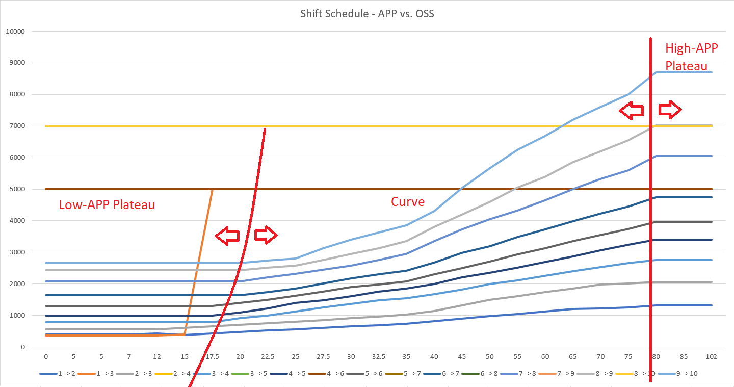
While OSS is a helpful parameter to use for transmission calibration - given customer interest in changing tire size - it is not as intuitive as engine RPM or vehicle speed. To address this, we have created a helpful spreadsheet tool to convert OSS into vehicle speed and engine RPM for upshift and downshift schedules; this spreadsheet also includes graphical representations of the shift schedules. Download with the link below:
10R80 Shift Schedule Converter Tool.xlsb.xlsx
Conversion Tool Notes:
- Vehicle Speed is based on stock tire circumference.
- Engine Speed values are approximate and do not account for converter slip.
- You can only edit the schedule data in the "Upshift Map (Copy from ATP): EDITABLE" chart; do not try to edit data directly in the Vehicle Speed or Engine RPM charts.
Tuning Tips:
One of the most challenging parts of creating a refined set of shift schedules for any vehicle is finding balance between "responsive" and "busy". With the number of gears at play in the 10R80, this becomes even more difficult. Here are a few factors to consider when creating shift schedules:
- Spacing between upshift and downshift schedules: A lot of improvement can be made to the responsiveness of the transmission by increasing the values found in the downshift schedule tables. However, you do not want to increase these values such that they come close to, or overlap with, upshift schedules at similar throttle inputs. The closer the downshift schedule is to the upshift schedule, the busier the transmission will feel - never really settling on a gear and annoying the driver. Here, it is helpful to consider shift points in terms of vehicle speed (reference the spreadsheet above to convert OSS to vehicle speed).
- Configuring the shape of the upshift and downshift schedule curves: It is helpful to consider the shape of your shift schedules in three chunks - low-APP plateau, the curve, and the high-APP plateau (see image below). Play around with the APP breakpoints for these sections to find a shift schedule that meets the driver's preferences.
- Low-APP shift points: Increasing low-APP shift points too high can worsen both driver experience (holding a gear too long) and fuel economy. Configure these shift points along with the width of the low-APP plateau so that the vehicle is comfortable and efficient around town, but holds gears adequately to improve driving behavior.
Shift Characteristics:
The 10R80 control strategy allows for 3 unique configurations of shift characteristics. These sets of tables will be labeled 'Base', 'Alternate 1', and 'Alternate 2'. The majority of the control tables for oncoming/offgoing clutch pressure curve characteristics have yet to be defined and will be added at a later date. For the time being, you can use the "Shift Characteristic Configuration" table to change what set of shift characteristics are used in a given drive mode.
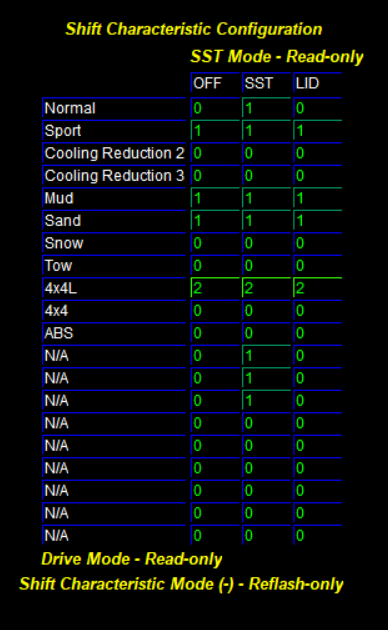
In this table, 0 = Base, 1 = Alternate 1, and 2 = Alternate 2. The LID column refers to "Lever in Drive", and the SST column refers to manually commanded shifts (shift lever in 'M' and commanding shifts via steering wheel paddles and/or shifter-mounted rocker switch). For example, if you wanted to make Normal drive mode shift like Sport mode, configure the LID column value for Normal to be 1. Similarly, if you wanted to configure the trans. to shift softer in Sport drive mode, configure the LID column value for Sport to be 0.
Torque Management:
The Shift Torque Modulation family of tables control the maximum permitted engine torque during a shift event. This system will use ignition timing control to reduce power during shifts; you will also notice that the engine monitor Spark Source will change to 3 when shift torque management is actively reducing ignition timing. Varying the extent of timing reductions during a shift is key to dialing-in ideal shift firmness and power delivery. These tables are specific to the Shift Characterization Configuration of each drive mode - Base, Alt. 1, and Alt. 2. They are sectioned into upshift and downshift categories, and then further broken down by each specific gear change type (1-2, 1-3, 2-3, 2-4, etc.). Each table has axes of Turbine Speed and Turbine Torque, the latter of which is an estimated value. The table data itself represents the maximum allowed engine output during a shift event - spark cut will be used if engine output exceeds this value.
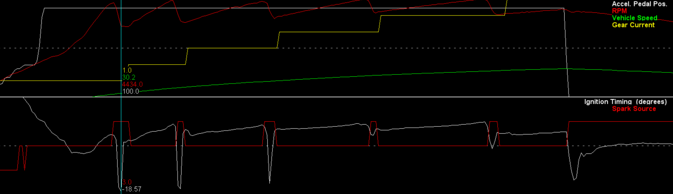
To begin tuning shift torque modulation, it is helpful to get a baseline. Below is a datalog taken from the drag strip in our development 2018 Raptor, which at the time was equipped with our full Stage 2 package and a stock transmission tune; this pass was done with traction control off, in 4A, and in Sport drive mode. Notice that Spark Source spikes to 3 during shifts; at the same time, notice how Ignition Timing drops sharply to reduce power during the shift. You can also see how small the torque reduction is for the notoriously harsh 4-5 shift compared to other gears. Increasing torque allowed will create a shallower dip in timing; decreasing torque allowed will create a deeper dip in timing.
If you're tuning on the dyno, you can assess torque delivered to the wheels through multiple shifts. To do so, use an inductive clamp on a coil harness to get a usable RPM signal across multiple gears. Then, configure your display to show engine speed and torque as the y-axes, and time as your x-axis. Then, you'll be able to plot your changes for effective torque delivered to the wheels during a shift. The example below shows a stock ECU/TCM 2018 Raptor shifting 3-4, 4-5, and 5-6 in Normal drive mode:
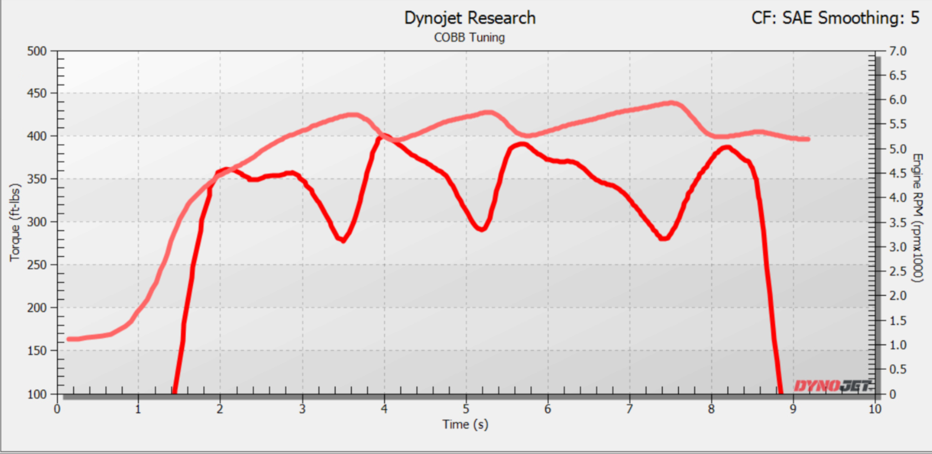
This plot shows a stock ECU/TCM 2018 Raptor shifting 3-4, 4-5, and 5-6 in Sport drive mode:
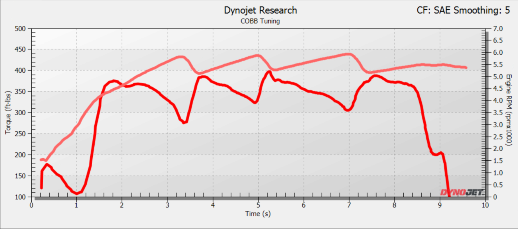
Notice how the 4-5 shift torque reduction in the Sport drive mode plot corresponds with the small ignition timing cut from the drag strip datalog shown above - the torque hole is shallower and the torque overshoot is sharper.
In comparison, the 2019 stock calibration uses a larger torque reduction for the 4-5 Sport mode shift, along with several other changes to oncoming/offgoing clutch element pressures and ramp rates in order to achieve a better feeling shift.
Backout Delay:
You may have noticed when driving in Sport mode that, after applying significant throttle/going WOT, the transmission will not upshift until you apply ~10% throttle. Ford refers to this system as Upshift Backout, which has both delay and inhibit components. The purpose of this system is to keep the trans. in a lower gear once the driver starts driving in a "sporty" fashion. While this may work well under certain conditions, we have found that it simply annoys the majority of Raptor owners.
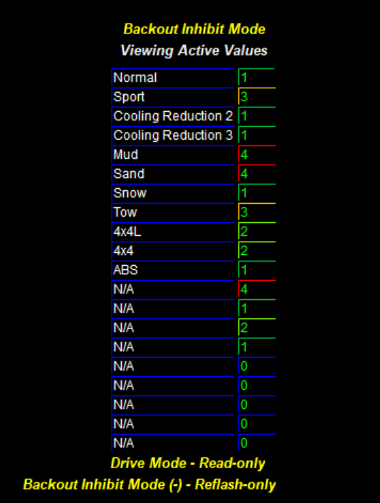
This table controls the backout inhibit function of the transmission. You will find that drive modes with inhibit mode values of '1' will generally allow upshifts, and drive modes with inhibit values of '3' will generally not allow upshifts.
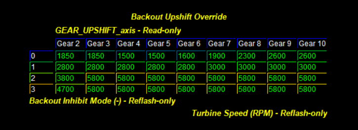
Consult the table below for upshift inhibit RPM settings per mode:
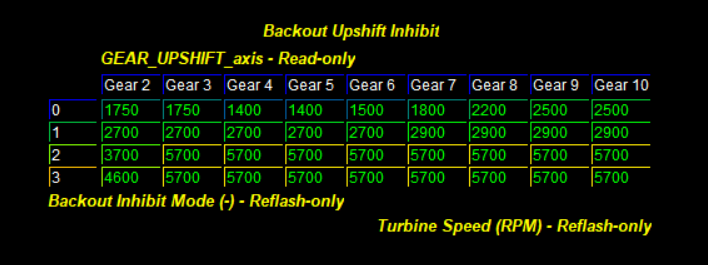
Note that the y-axis on this table ranges 0-3, where the Backout Inhibit Mode table above ranges values 1-4. There is just a single value offset between these; "1" in Backout Inhibit Mode table will map to "0" in the Backout Upshift Inhibit table axis. The table data represents the turbine speed (essentially engine RPM) below which, backout upshifts will be inhibited. Note this will only happen at closed throttle. You could see how setting Sport mode to '3' (which maps to the '2' row in this table) could be annoying - not upshifting unless engine RPM was above 5700.
If and when you modify this inhibit table, you will also need to modify this table:
The values in this table must be higher than those found in the Backout Upshift Inhibit table. Try to keep a margin of at least 100RPM.