
971250 – Mazdaspeed3 Lightweight Tubular Anti-Sway Bar Kit
2007+ Mazda 3
Congratulations on your purchase of the COBB Tuning Mazdaspeed Tubular Anti-Sway Bar Kit! The following instructions will assist you through the installation process. Please read them BEFORE beginning the install to familiarize yourself with the steps and tools needed. If you feel you cannot properly perform this installation, we HIGHLY recommend you take the vehicle to a qualified and experienced automotive technician.
Table of Contents
| Table of Contents |
|---|
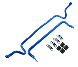
Parts List
- Front sway bar
- Rear sway bar
- (2)Front bushings and brackets
- (2)Rear bushings and brackets
- Packet of Silicon Grease
Tools Needed
- Phillips head screwdriver
- Flathead screwdriver
- 3/8" 7mm socket
3/8" 11mm socket
- 3/8" 16mm
- 3/8" 17mm socket
- 3/8" 18mm socket
- 3/8" 19mm socket
- 3/8" 21mm socket
- 3/8" 14mm deep socket
- 3/8" 15mm deep socket
- 3/8" T50 Torx Bit
- 3/8" E10 inverted Torx
- 3/8" E12 inverted Torx
- 3/8" E14 inverted Torx
- 3/8" E18 inverted Torx
- 3/8" 5mm Hex Key or Hex Socket
- 1/2" breaker bar*
- 1/2" 16" extension*
- 1/2" 14mm socket*
- 1/2" 23mm deep socket
- 14mm offset wrench
- Oxygen Sensor Wrench
- 7mm Hex Driver
- M3 Allen Key
- M4 Allen Key
- M10 Allen Socket
- 8mm Ratcheting combination wrench
- 10mm 17mm combination wrench
- 11mm combination wrench
- 12mm combination wrench
- 13mm combination wrench
- 14mm combination wrench
- 15mm combination wrench
- 16mm combination wrench
- 17mm combination wrench
- 18mm combination wrench
- 19mm combination wrench
- 21mm combination wrench
- Torque Wrench
- Torque Wrench
- Trim removal tool
- Hose cutter
- Drain pan
Section 1
Section 2
Section 3
Section 4
Section 5
Links
MAP Notes
Helps to figure out which map you should be on given the parts installed to your car
Links for related partsFront Sway Bar
- Raise the vehicle using a jack and stands on a flat level area.
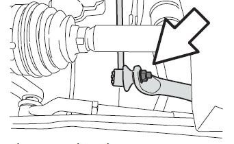
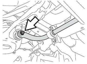
- Disconnect both of the lower end links by removing the nuts from each side, then push the links out of the way.
- Completely remove the downpipe exhaust hangers.
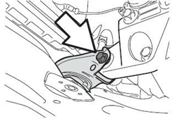
- Disconnect the lower engine mount from the subframe by removing the mounting bolts
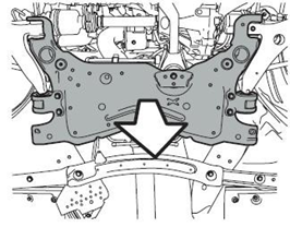
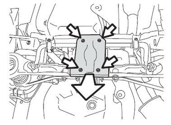
- Support the engine subframe with a jack or similar device. With the subframe supported remove the two front subframe bolts by running an extension through the access holes in the front lower control arms. Then remove the three bolts holding the rear mounting plates and remove the mounts.
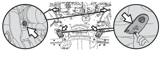
- Using a jack, lower the rear of the subframe until it hangs freely from the lower control arms and transmission mount. Pay attention not to let the downpipe hangers interfere with each other on the way down.
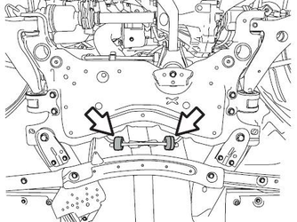
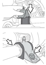
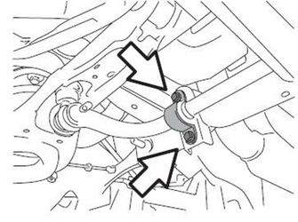
- Remove the 2 anti-sway bar bushing bracket bolts on either side of the vehicle and remove the tbrackets from the vehicle. At this point, the bar should no longer be connected to the vehicle.
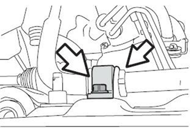
- You should now be able to carefully remove the sway bar. It will take some twisting and turning to get out.
- In order to install the new COBB front Anti-sway bar, repeat the steps in reverse order, making certain to thorougly grease up the inside of the front bushings to avoid any suspension noise, and using thread locking compound on all the bolts and nuts before torquing them down properly.
Rear Sway Bar
- Raise the vehicle using a jack and stands on a flat level area.
- Remove the 4 rear subframe brace bolts and set them aside.
- Disconnect the end links by removing the nuts from both sides and pushing them out of the way.
- Remove the four bracket bolts and then remove the brackets and sway bar.
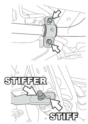
- In order to install the new COBB front Anti-sway bar, repeat the steps in reverse order, making certain to thorougly grease up the inside of the front bushings to avoid any suspension noise, and using thread locking compound on all the bolts and nuts before torquing them down properly. The inner holes will be the stiffer of the two positions.
Customer Support
Phone support available 9am to 6pm Monday-Thursday. 9am to 4pm Friday (CST)
866.922.3059