811610, 822610 - Air/ Oil SeparatorWRX 2002 - 2014, STI 04-20 [Discontinued]

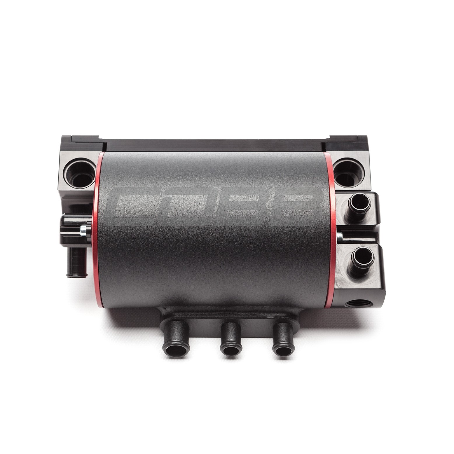
811610, 822610 - Air Oil Separator
Subaru WRX STI 2004 - 2020
Subaru WRX 2002 - 2014
Subaru Legacy GT, Outback XT 2005 - 2009
Subaru Forester XT 2004 - 2013
Congratulations on your purchase of the COBB Tuning Air Oil Separator! The following instructions will assist you through the installation process. Please read them BEFORE beginning the install to familiarize yourself with the steps and tools needed. If you feel you cannot properly perform this installation, we HIGHLY recommend you take the vehicle to a qualified and experienced automotive technician.
Table of Contents
A Special Note on Hose Installation
When installing the hoses and lines to and from the COBB Air Oil Separator, take special care to route them away from any sources of heat, ensure that they are free of kinks or obstructions, and secure them properly with zip ties to prevent movement and chafing. Utilize spring clamps at every connection point to avoid the potential for an air leak. Additionally keep in mind that the engine will move slightly so leave a small amount of play in the lines where it goes up to the AOS to allow for some movement without causing damage or stress on the lines.
Quick Reference for Hose Attachment
Stock TMIC Removal
- WRX 2002 - 2007
- WRX STI 2004 - 2020
- Forester XT 2004 - 2008
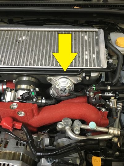
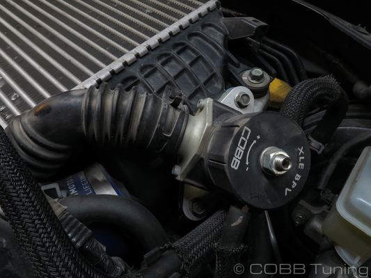
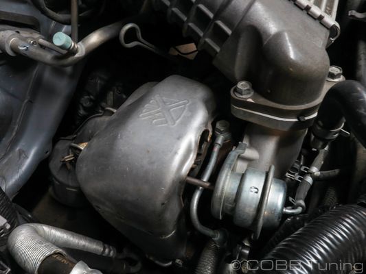
- Locate your stock bypass valve.
- Using a pair of pliers, remove the return line from the bypass valve.
- Remove the vacuum line from the factory bypass valve.
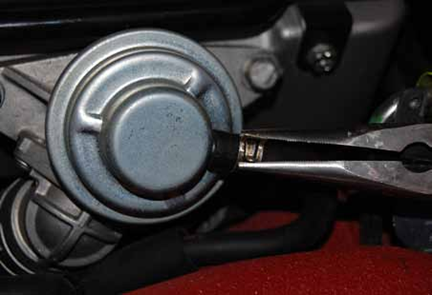
Using a 12mm socket with ratchet, remove the 2 bolts that hold the bypass valve in place and remove it from the car.
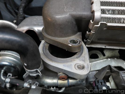
TIP: Make sure to keep an eye on the factory gasket behind the BPV. It can fall when you remove the valve and end up in difficult to reach locations!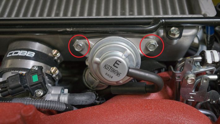
- Remove the bypass valve.
- Remove breather tubes from intercooler. Dikes can be helpful when removing the metal clamps or zip ties.
- Loosen the turbo outlet clamp using a screwdriver or appropriately sized socket (Typically 7-8mm) along with the (2) throttle body clamps using a screwdriver or 8mm socket.
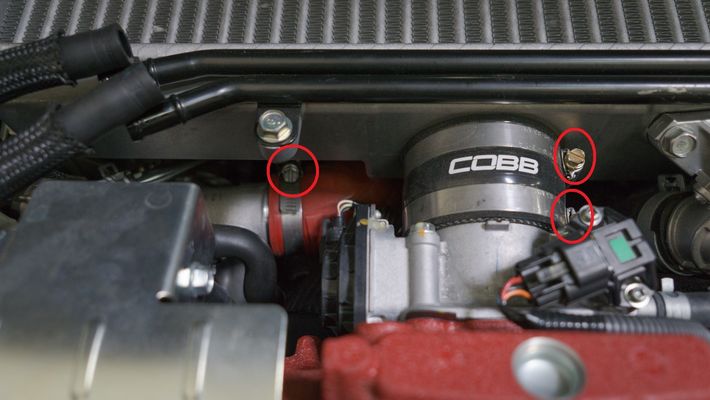
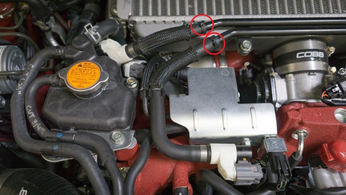
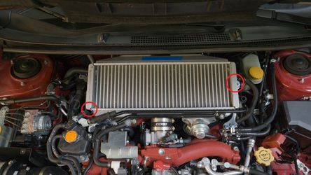
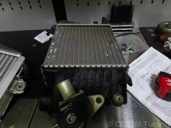
- Remove the two bolts holding the intercooler in place
- Gently wiggle TMIC free from engine bay by sliding it back and then out. Be careful to not damage your windshield wiper cowl.
With it off of the car, you can remove the metal PCV lines permanently.
This removal applies to the following vehicles
- 2008 - 2014 WRX
- 2005 - 2009 Legacy GT
- 2005 - 2009 Outback XT
- 2008 - 2013 Forester XT
- Locate the factory BPV and remove the recirculation hose by squeezing down the hose clamp with your pliers.
- Remove the vacuum reference line from the rear port of the BPV
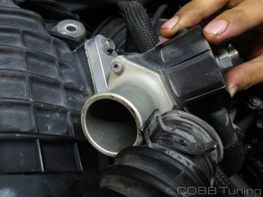
- Moving to the other side, unbolt the flange where it meets the turbo using a 12mm socket.
- Undo the hose clamp attaching the throttle body coupler to the intercooler. This will typically require a phillips screwdriver, 7 or 8mm socket.
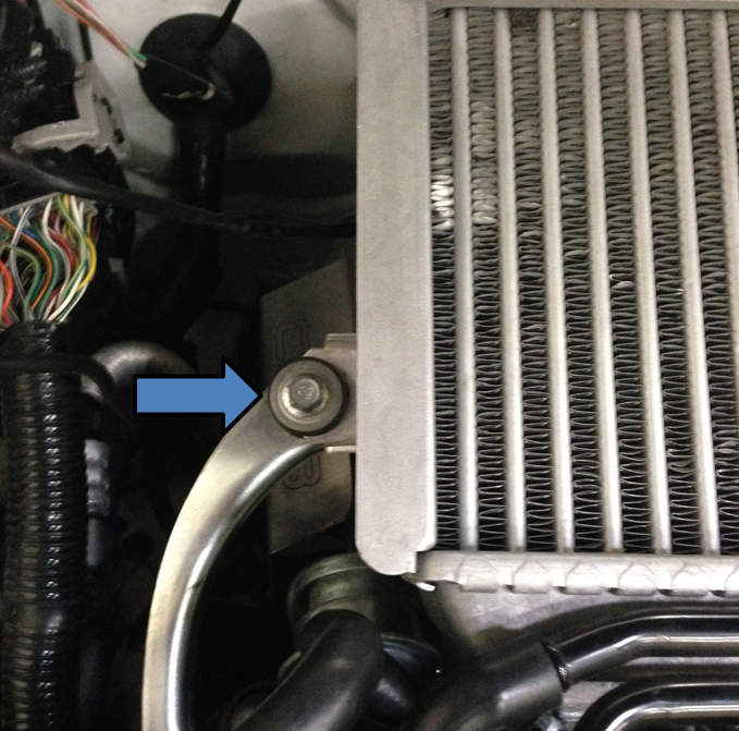
- Unbolt the remaining 12mm bolt going to the intercooler support bracket and remove the intercooler from the car.
Mounting Prep
Cruise Control (02-05 GD Chassis)
Cable Control Throttle Body With Cruise Control and Horn.
- If present the cruise control will need to be modified for the bracket to fit properly. To do so start by removing the bolts holding the silver bracket to the strut tower with your 10mm socket.
- Then remove the bolts from the black bracket holding that to the vehicle as well.
- Next you'll want to unbolt the bracket from the cruise control module using a screwdriver.
- Trim the black bracket using a saw or cutting disc. Make sure to wear appropriate protective equipment.
- Reinstall the cruise control module using the factory hardware.
- Bolt the modified bracket into the lower bolt hole the silver bracket utilised.
Horn Relocation (02-05 GD Chassis)
Some vehicles mount a horn to a bracket on the top of the strut tower. You'll want to move this out of the way as it blocks access and space for the AOS.
- Using a 12mm socket unbolt where the two horn brackets meet.
- Remove the two 12mm bolts holding the horn bracket to the top of the strut tower, the bracket can now be removed from the car and will not be reused.
- Move the horn towards the front side of the strut tower and bolt it down. It will give you more slack if you undo the limiting tape on the horn harness.
DRL Resistor Relocation (GD Chassis 02-07)
- Some models have the DRL resistor mounted in various ways in this area. You'll want to make sure it's cool before doing anything as it can get incredibly hot. Undo the two 12mm bolts holding the resistor to the bracket.
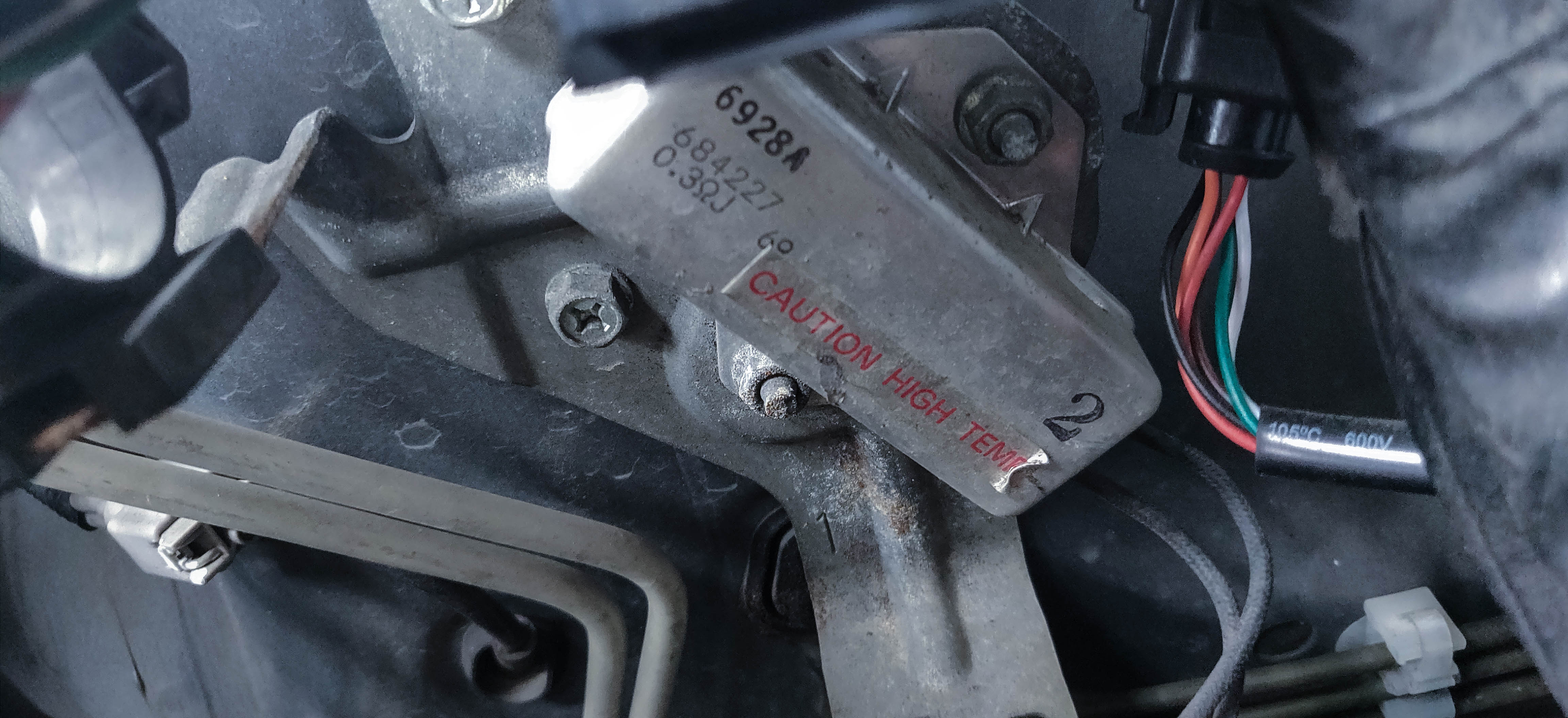
- Relocate this unit to the bottom of the forward two holes on the strut tower. You may need to flip the unit over or remove it from the 90 degree bracket to make it fit with the brake lines.
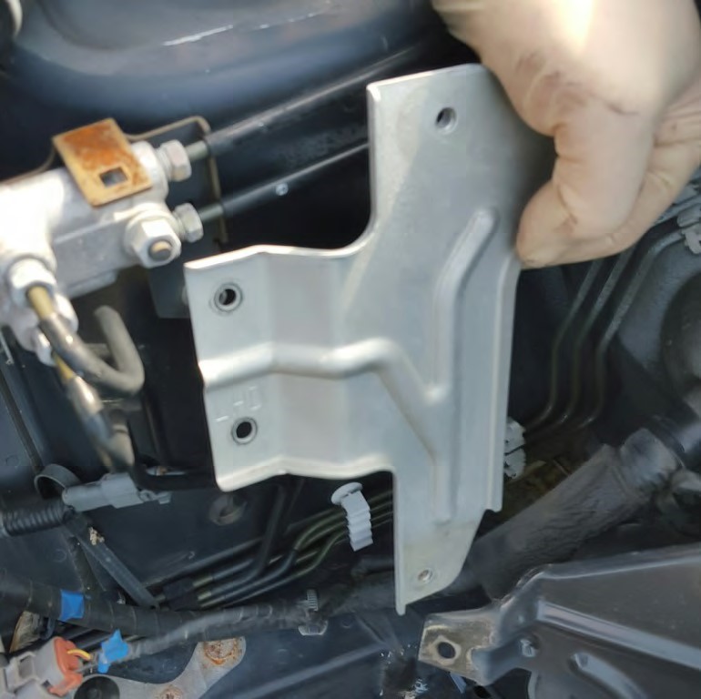
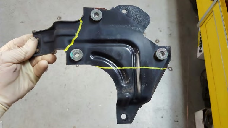
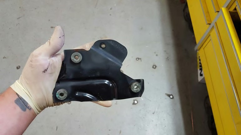
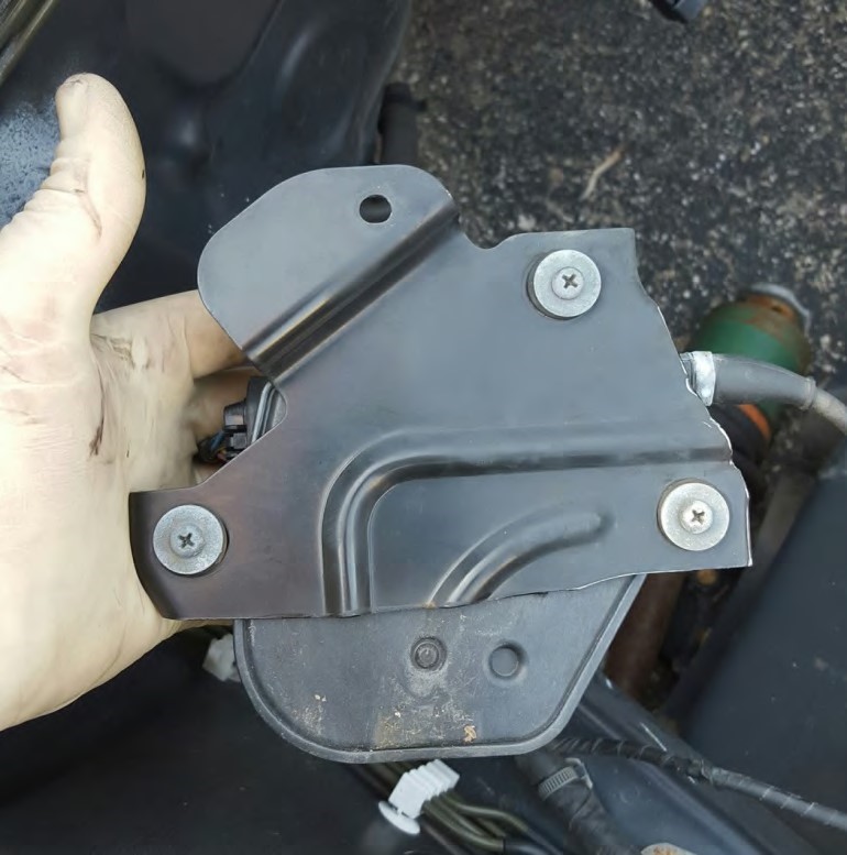
Harness Relocation (07 GD 08+ GR Chassis)
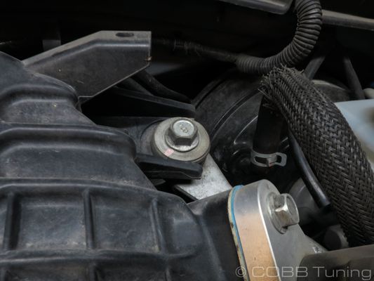
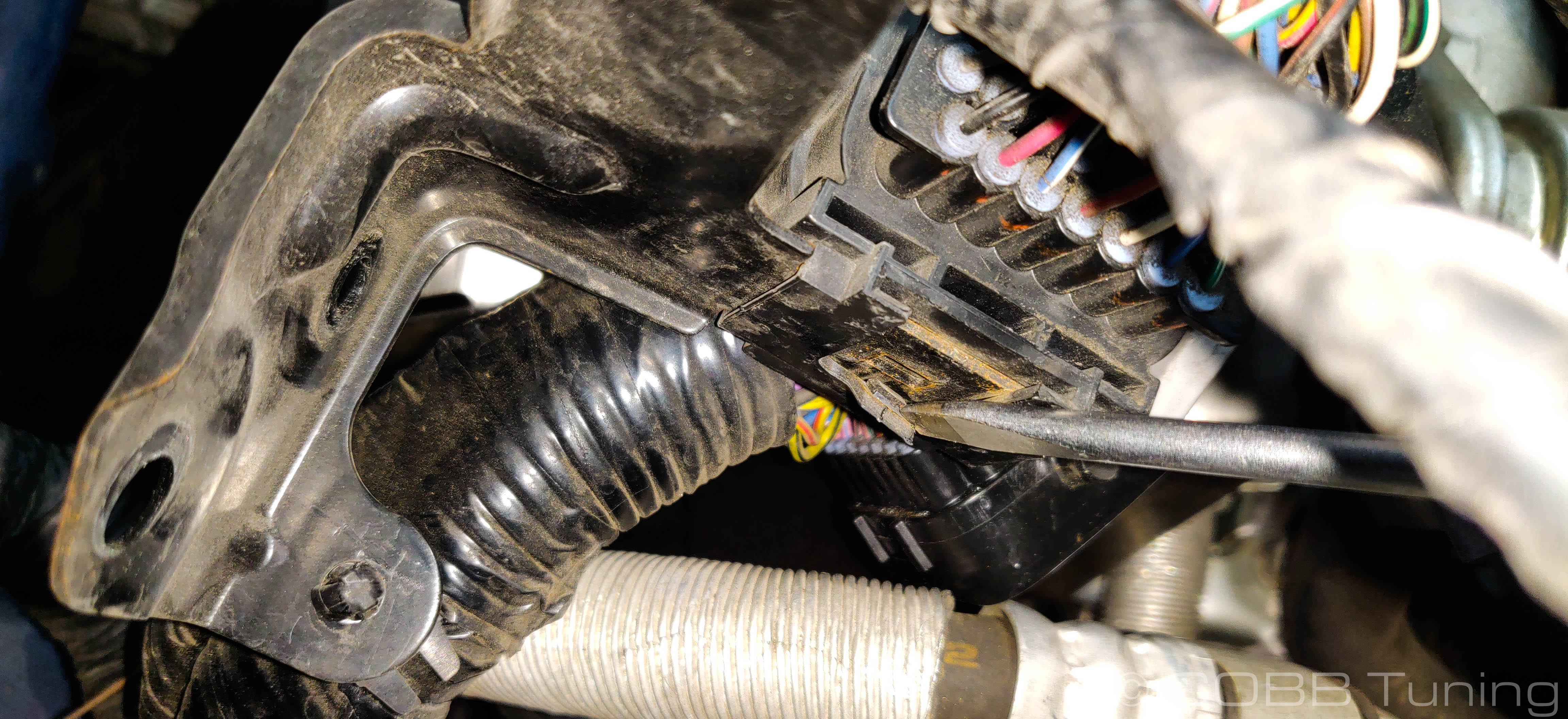
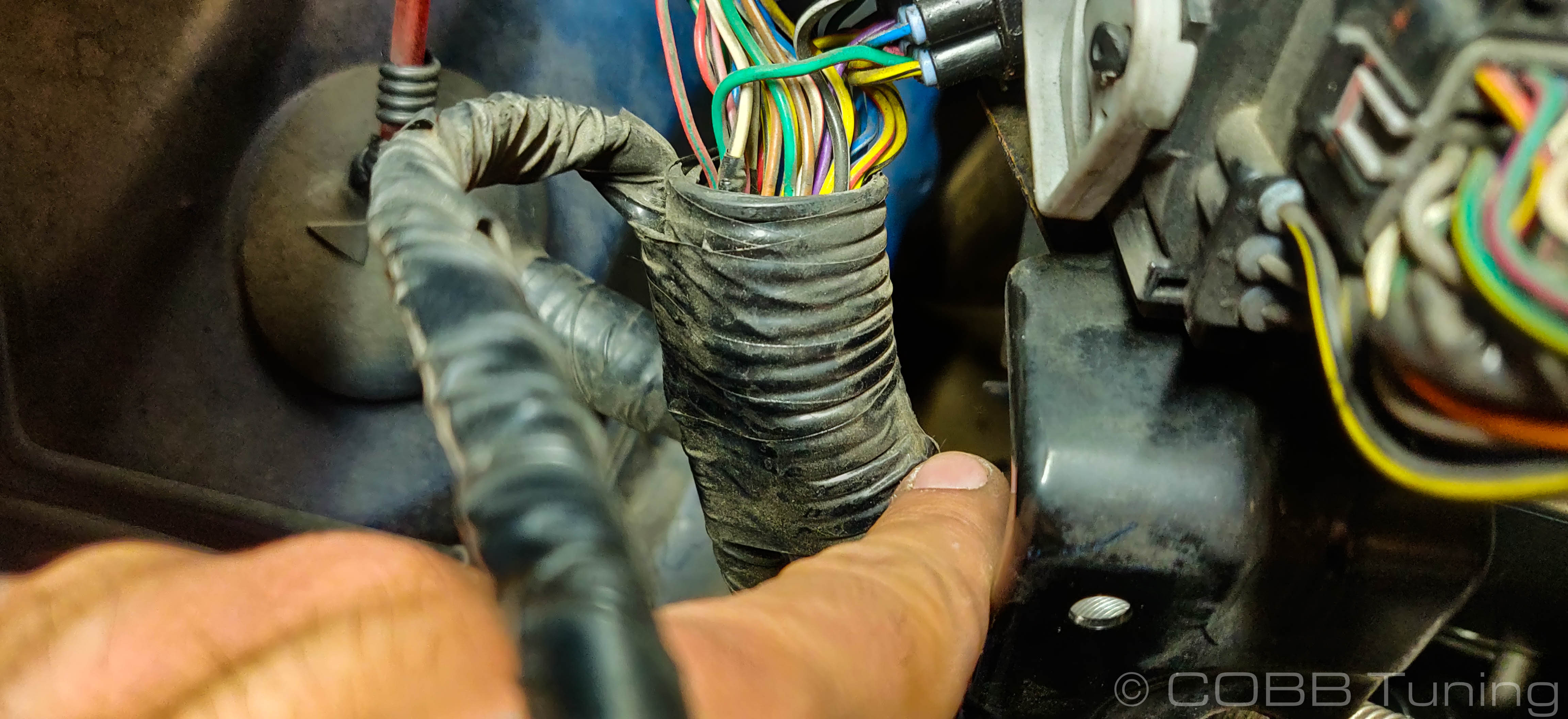
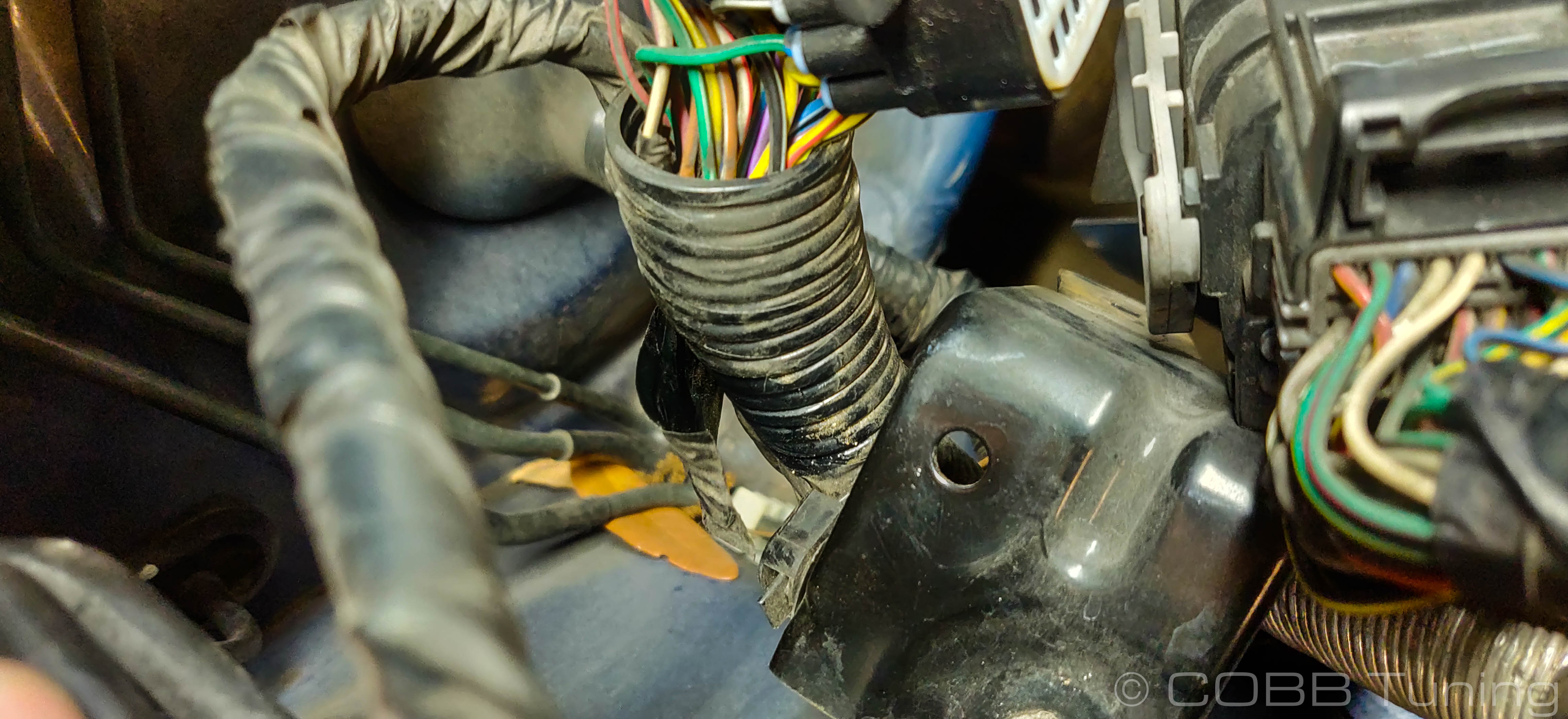
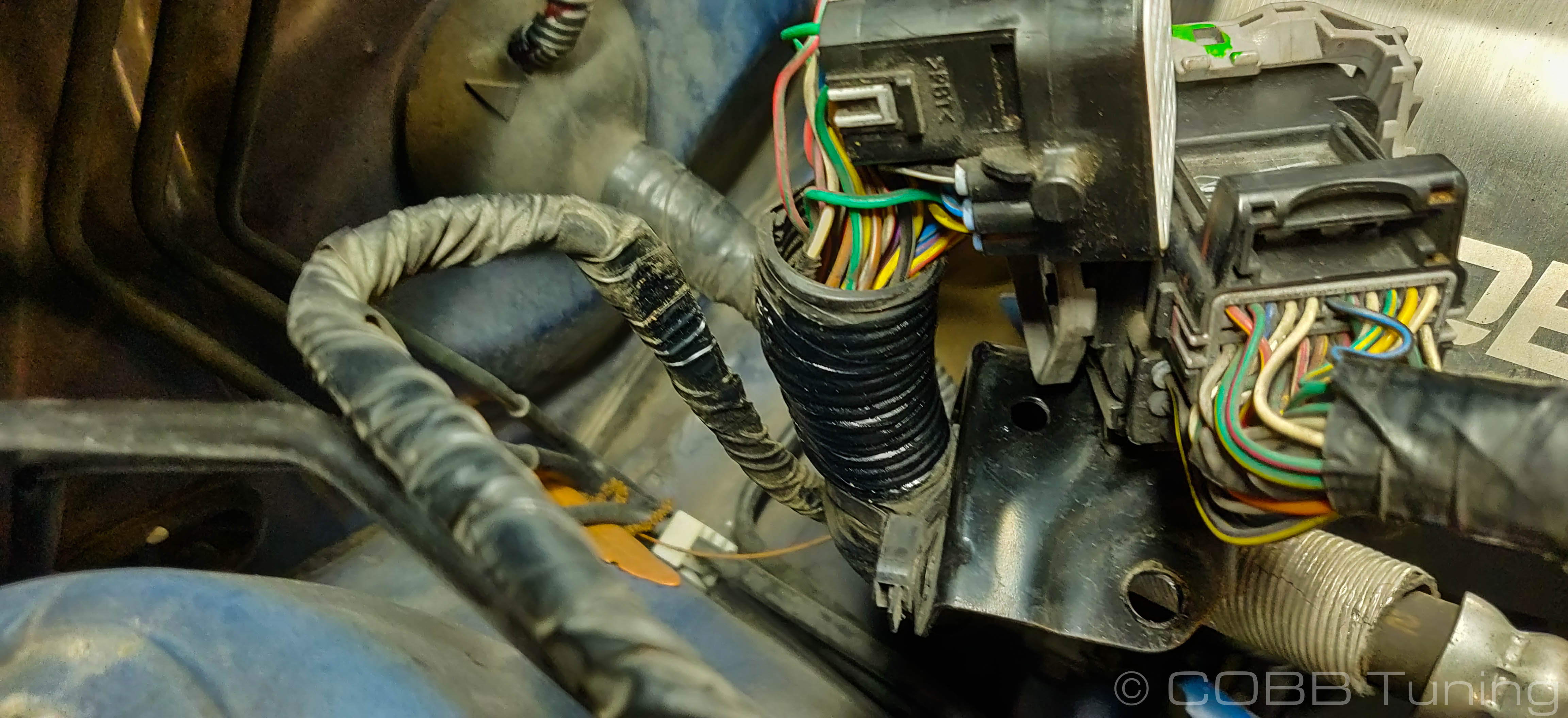
- Using a screwdriver, gently lift downward on the retaining pin holding the main engine wiring harness to the bracket. While doing so wiggle the connector towards the space the TMIC used to occupy. It should slip off easily if the pin is out of the way.
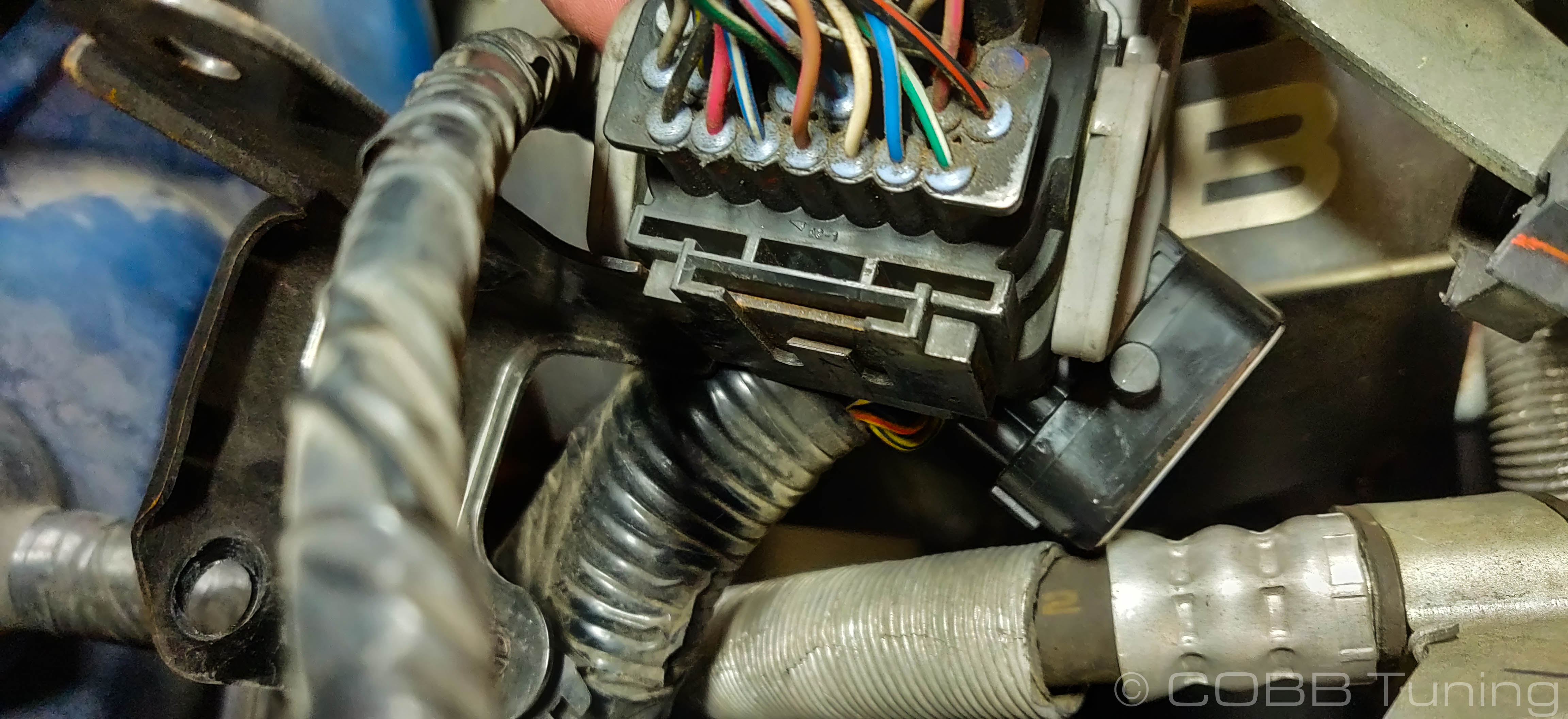
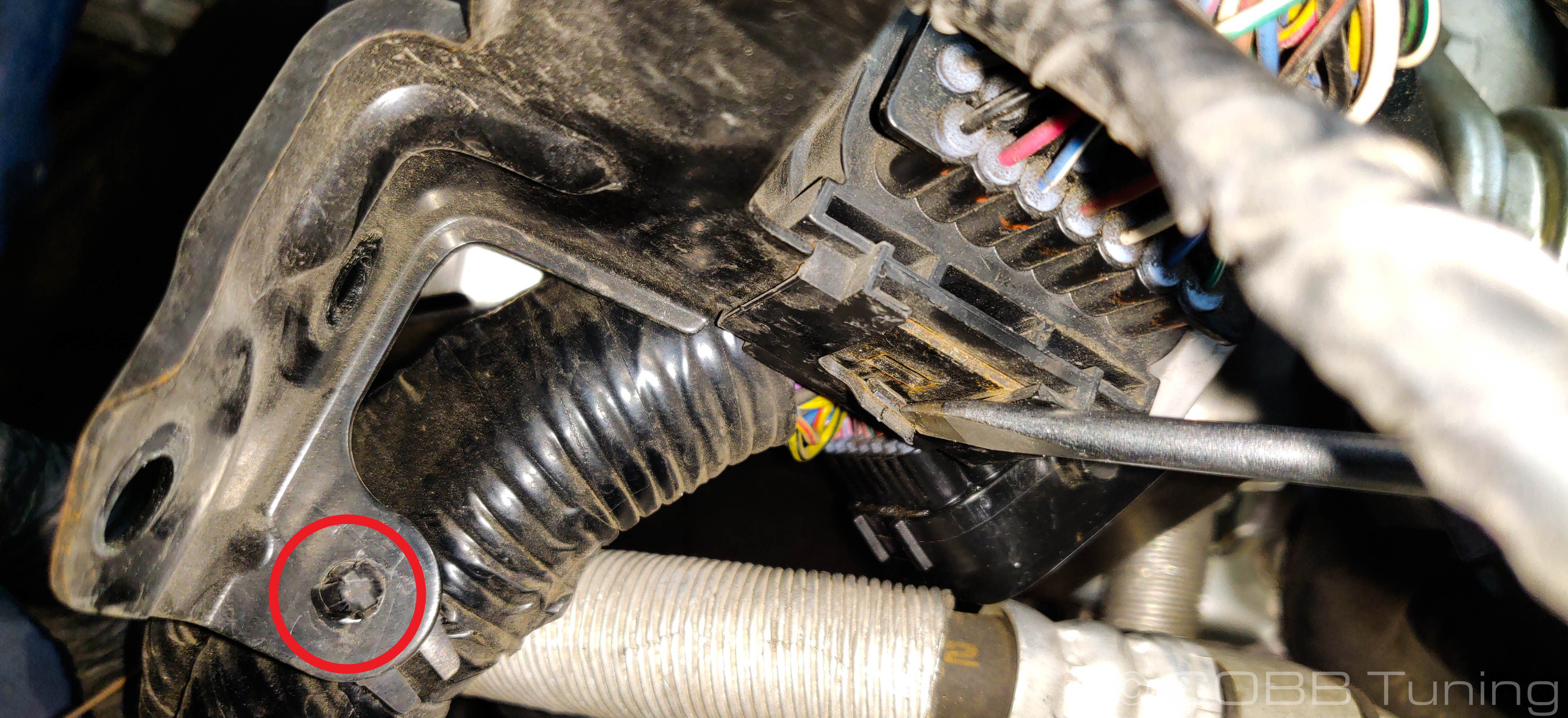
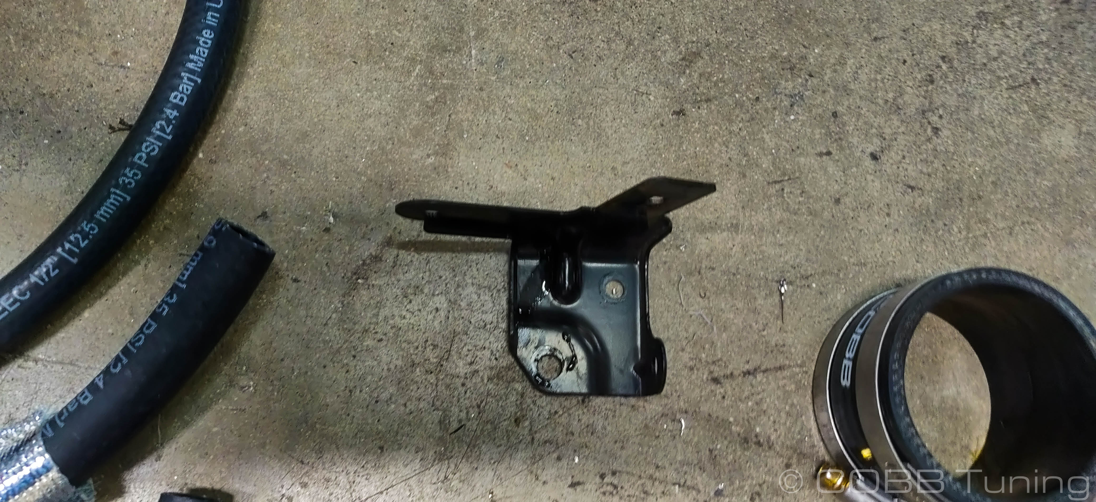
- Squeeze the harness clip holding the wiring harness to the bracket. Remove the bracket from the car and set it aside as it won't be used again.
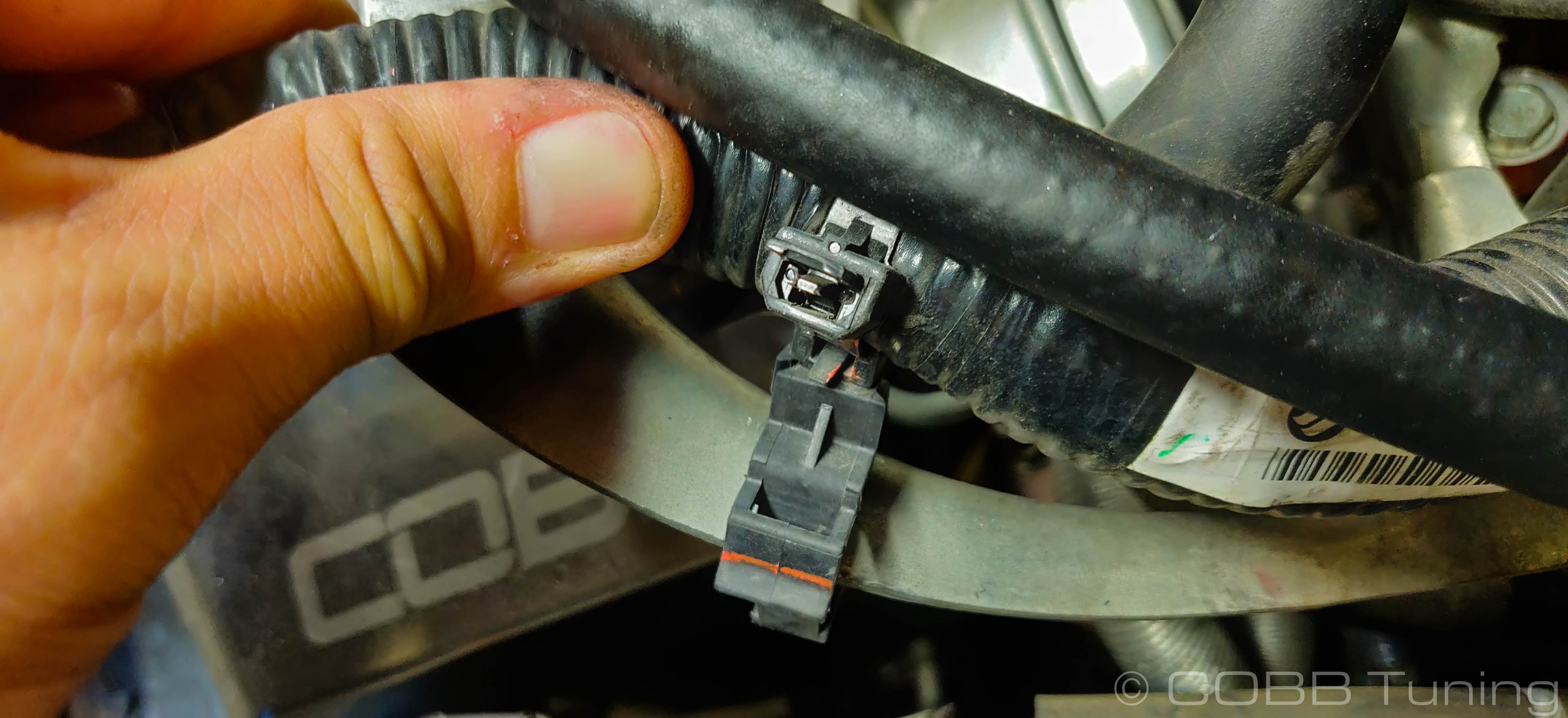
- Disconnect the o2 sensor connector from the harness, and squeeze the clip to remove it from the bracket.

- At the top of the harness near where the corrugated plastic sheething stops there should be an extra piece of electrical tape on the top few inches limiting the reach of the o2 sensor harness. Remove this strip but leave the rest of the tape in place for protection. You should be able to see an end to start unwinding from.
- Clean the adhesive off of your hands and the harness with either soap and water or a small amount of brake cleaner sprayed on a cloth.
- Release the harness clip holding it to the top mount intercooler bracket. This should allow you a bit more freedom to move it around.
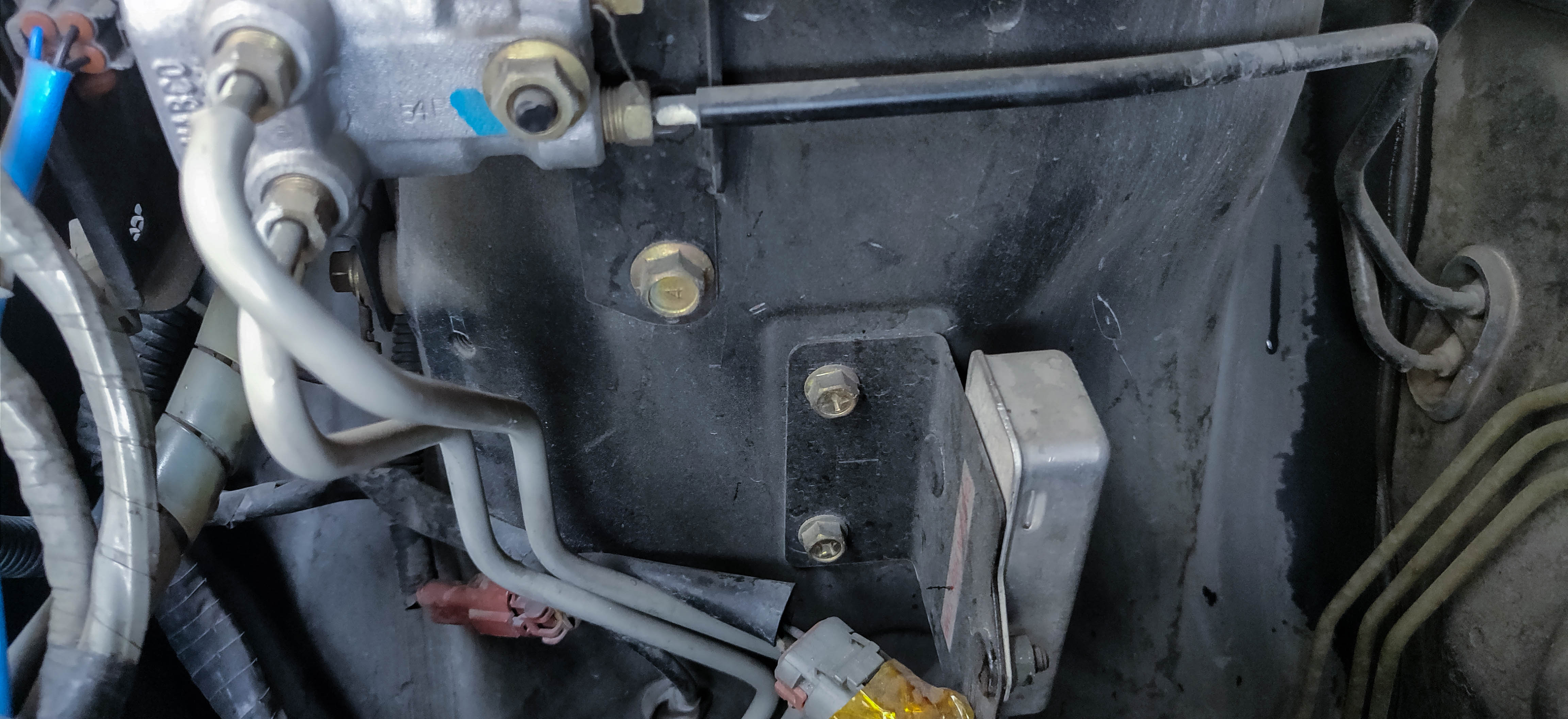
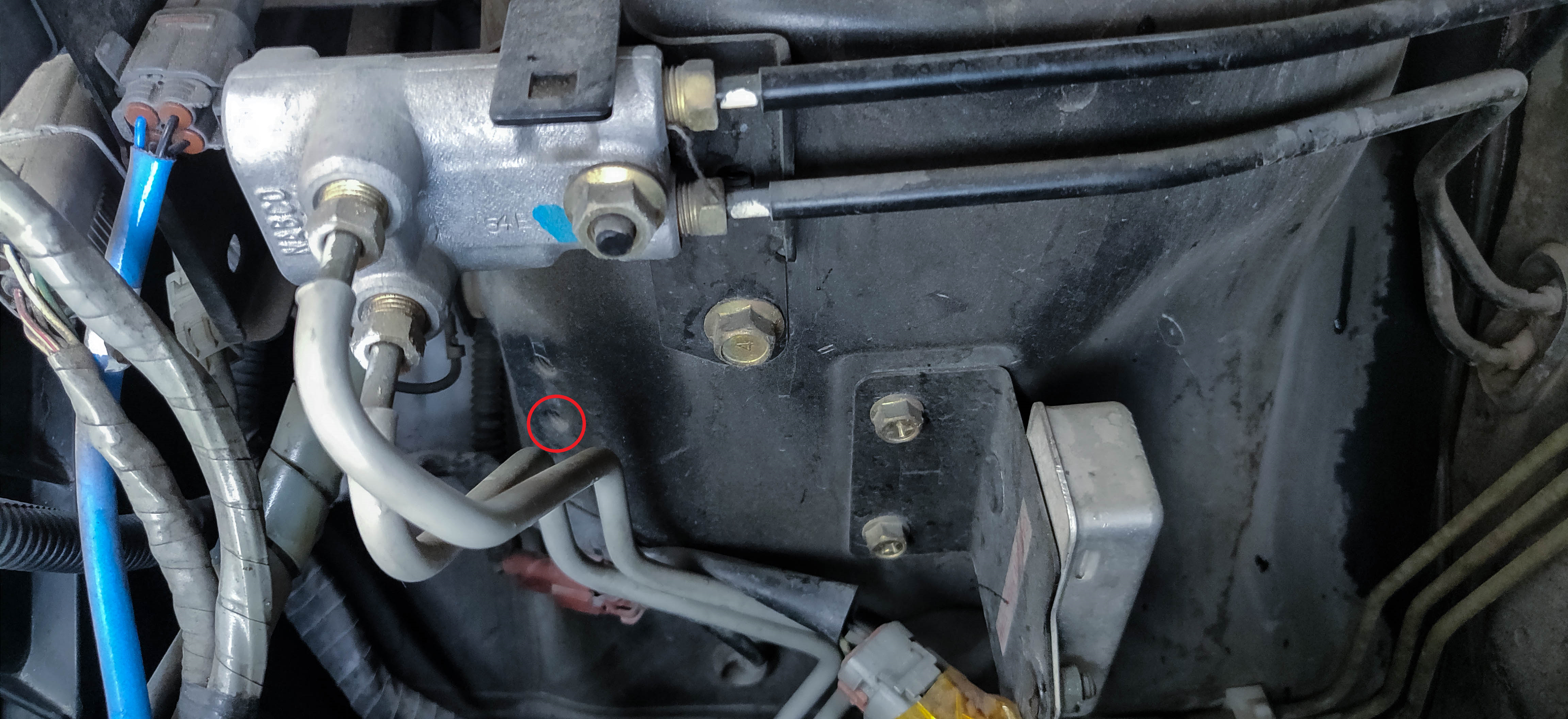
Mounting Area Modification
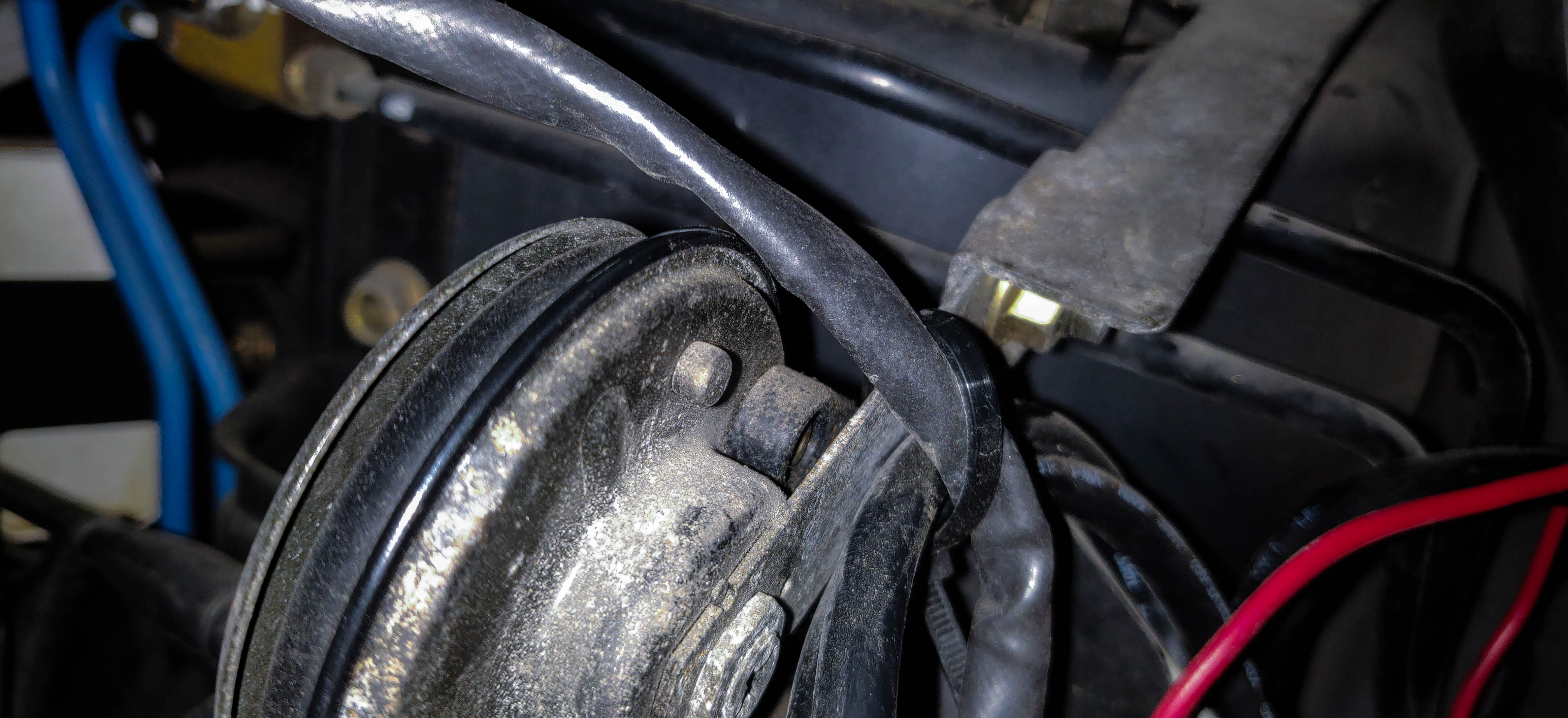
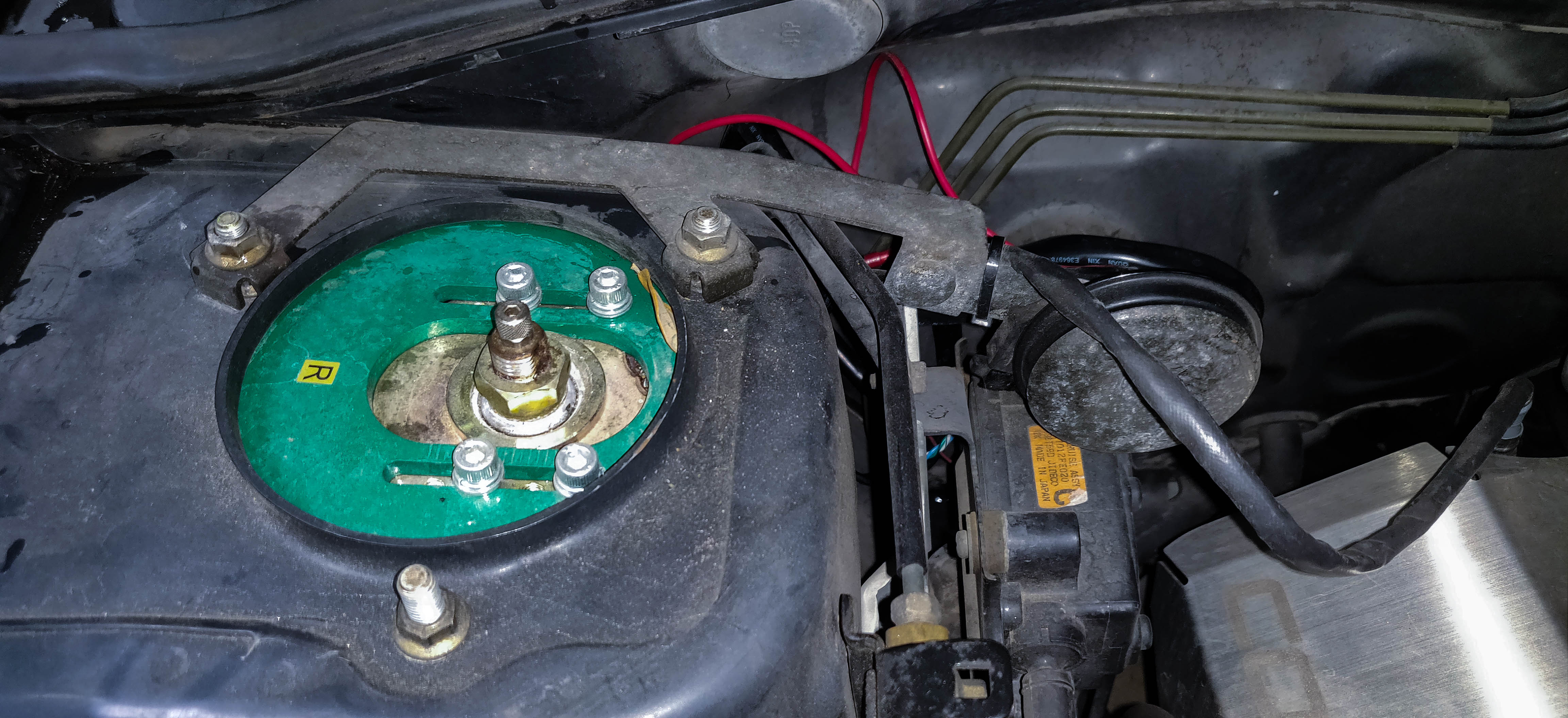
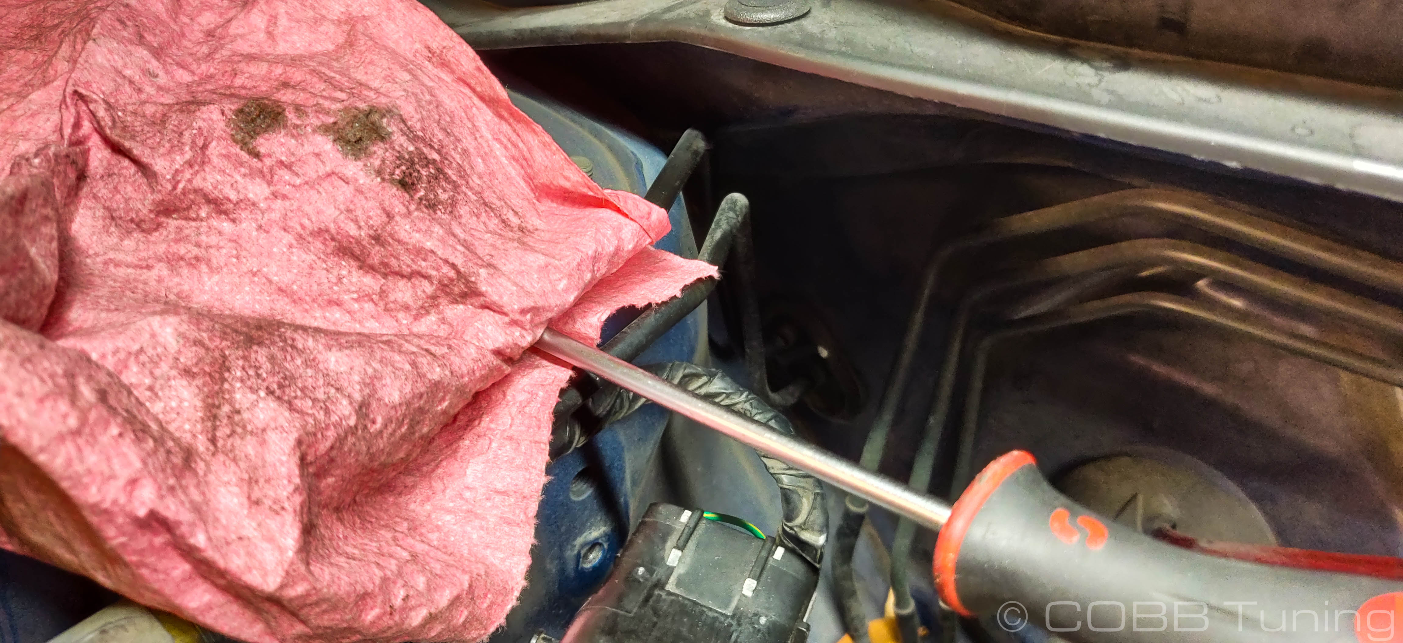
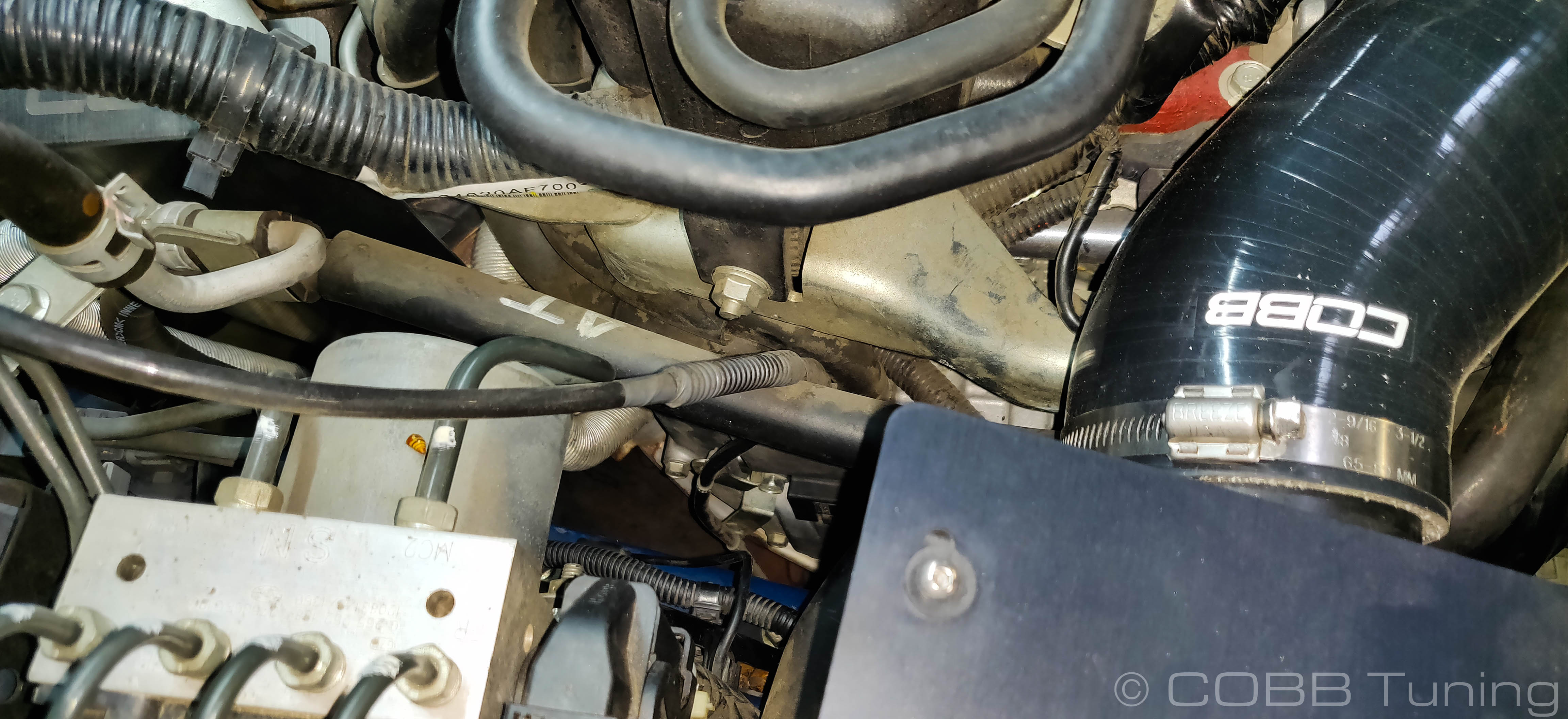
- Using a rag covering a screwdriver or pry bar, gently GENTLY move the brake lines up slightly. Getting the top one to an even height with the nut on the strut tower and the lower one spaced similarly to stock should give you the space required.
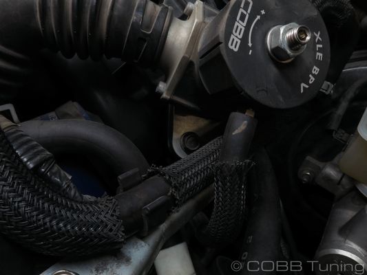
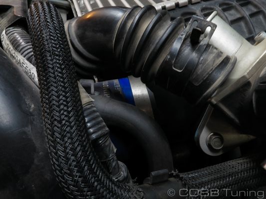
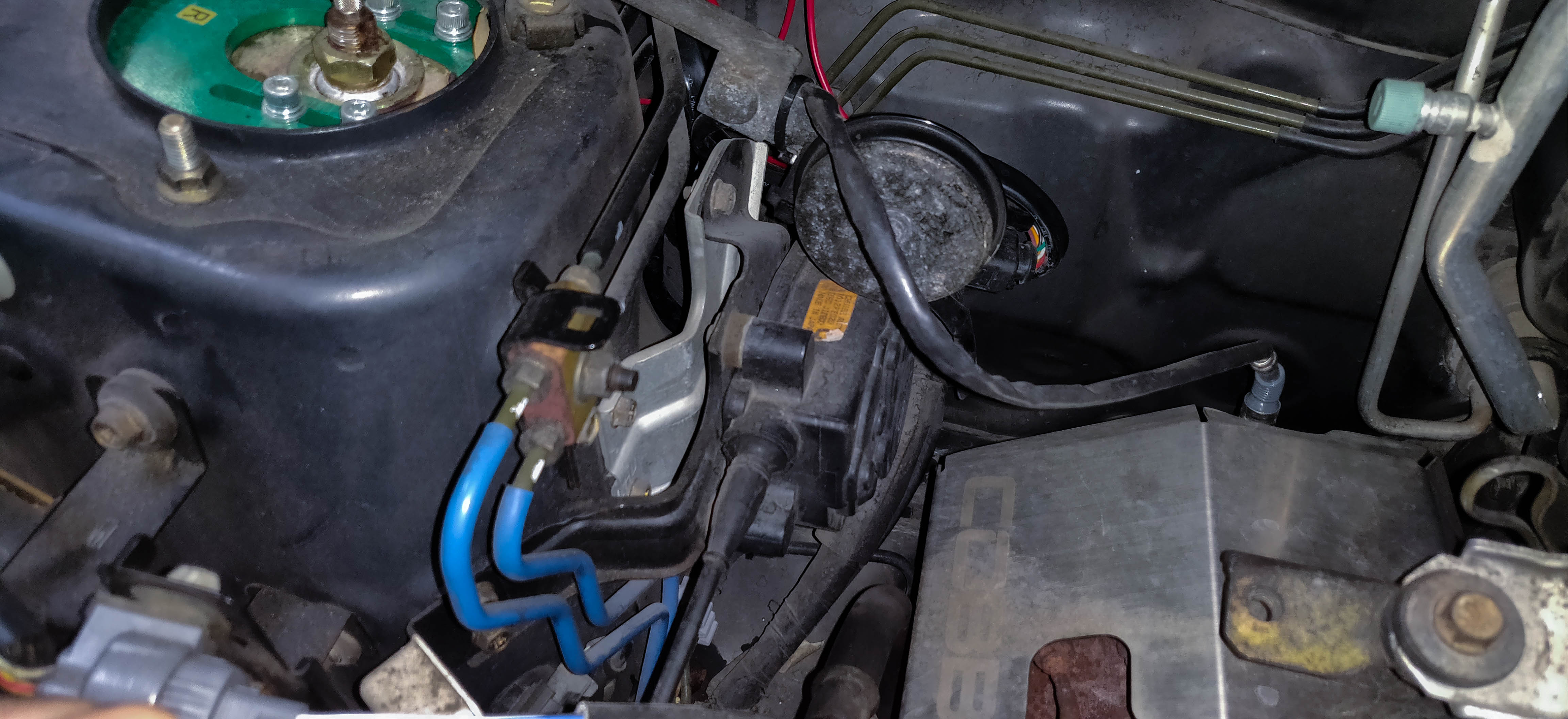
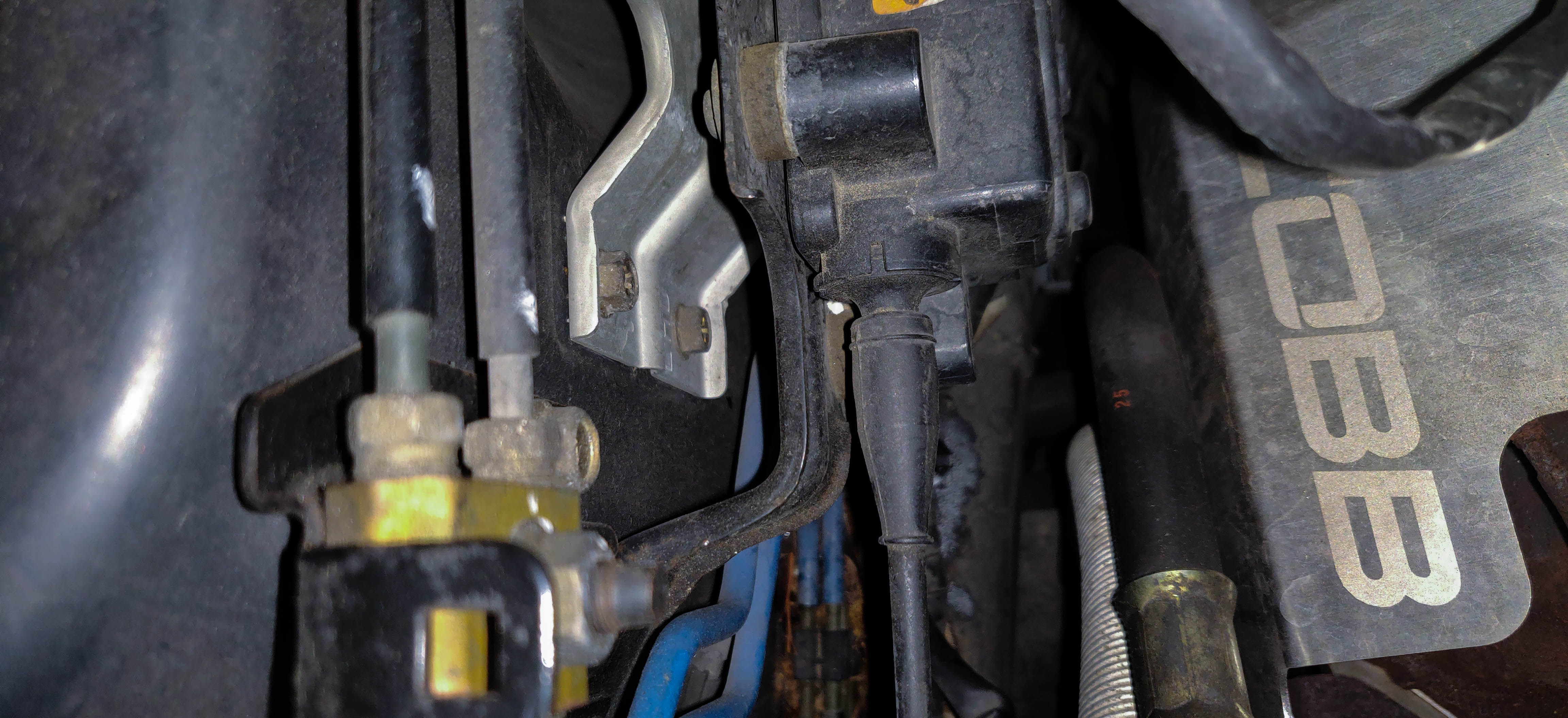
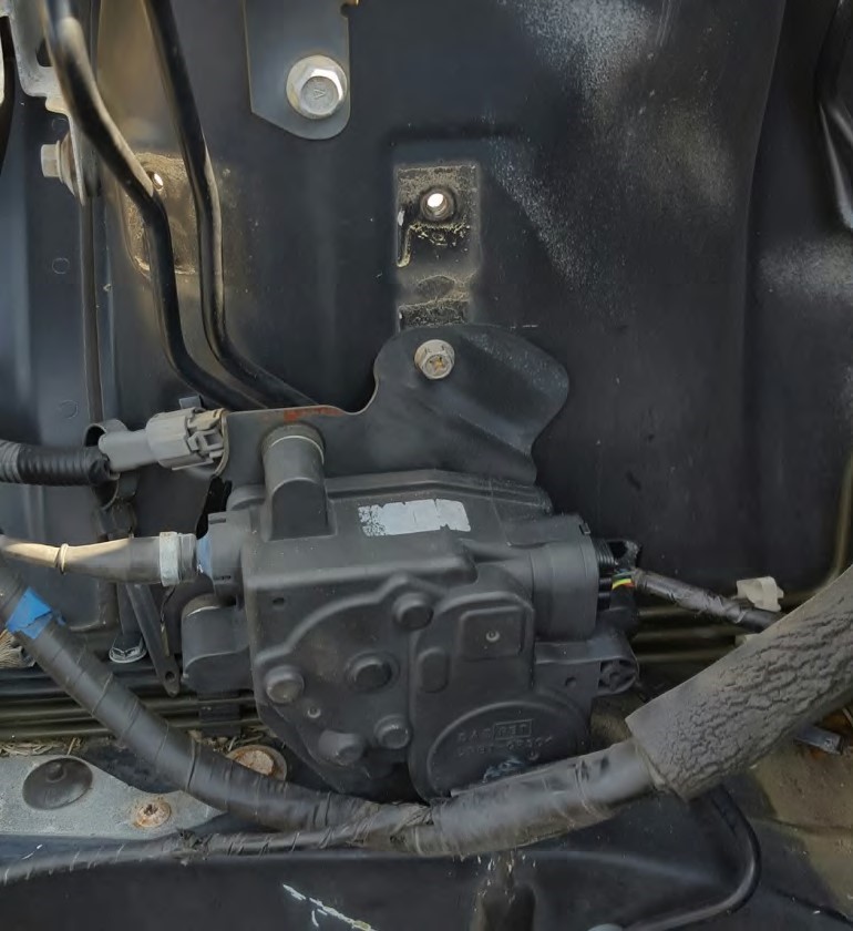
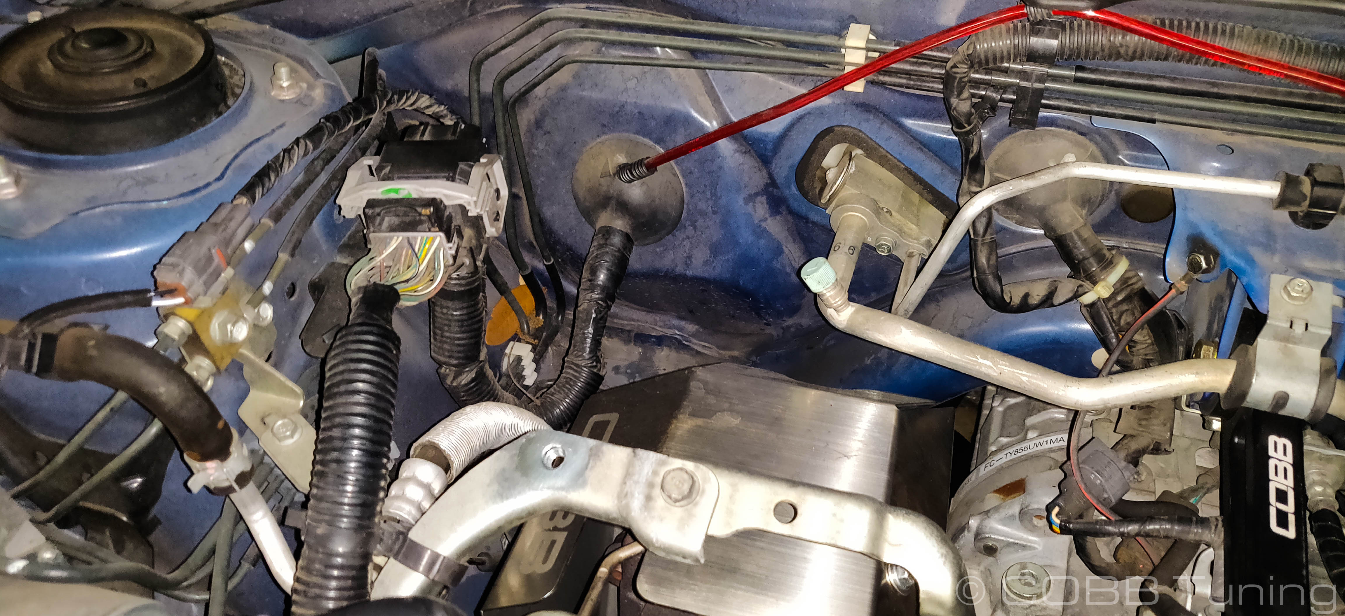
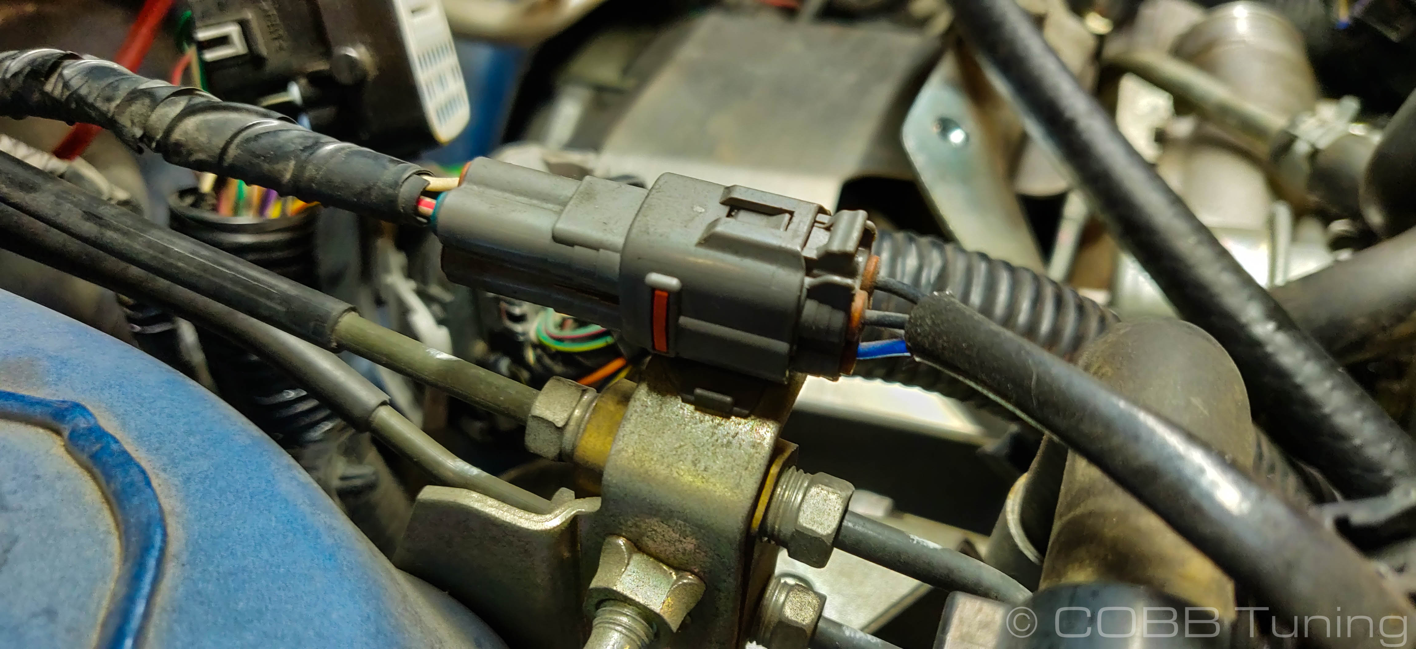
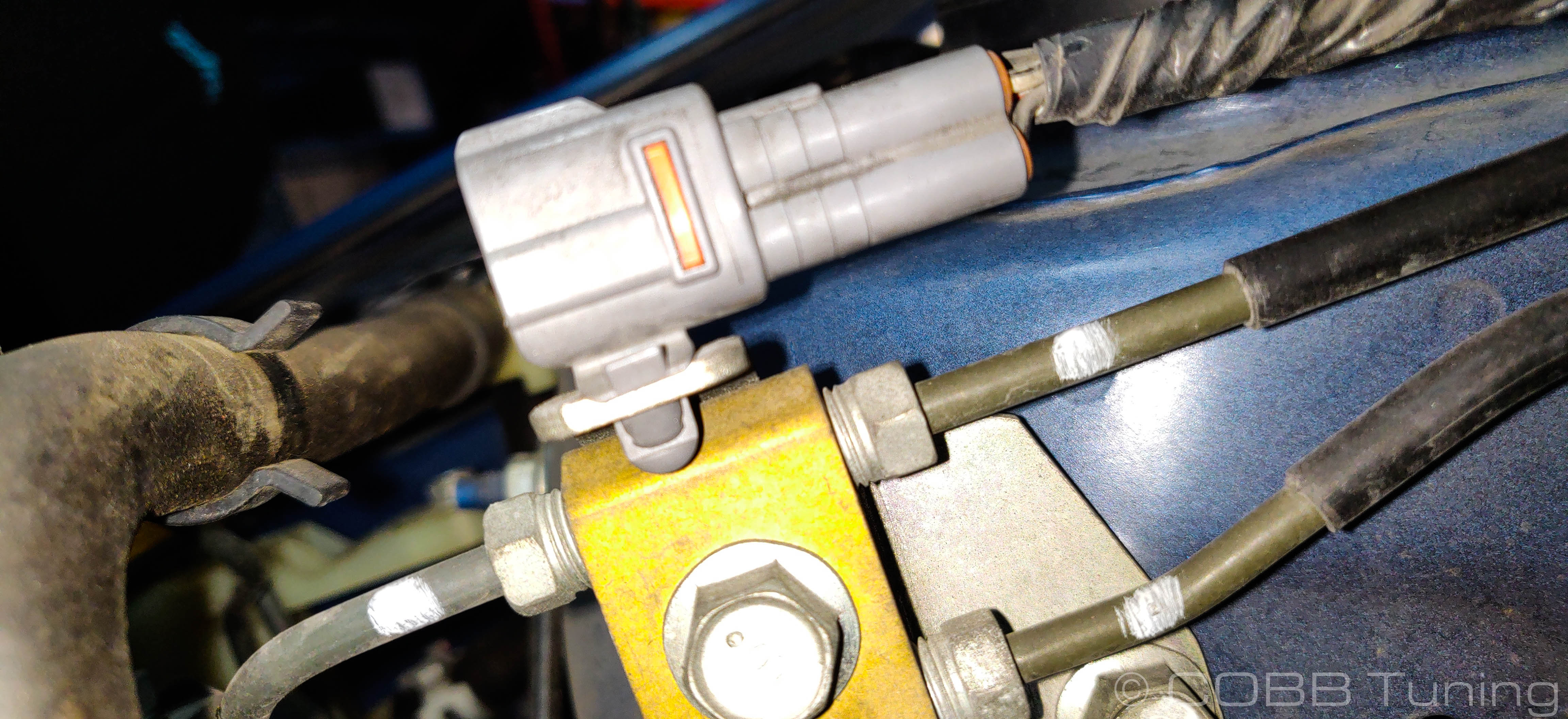
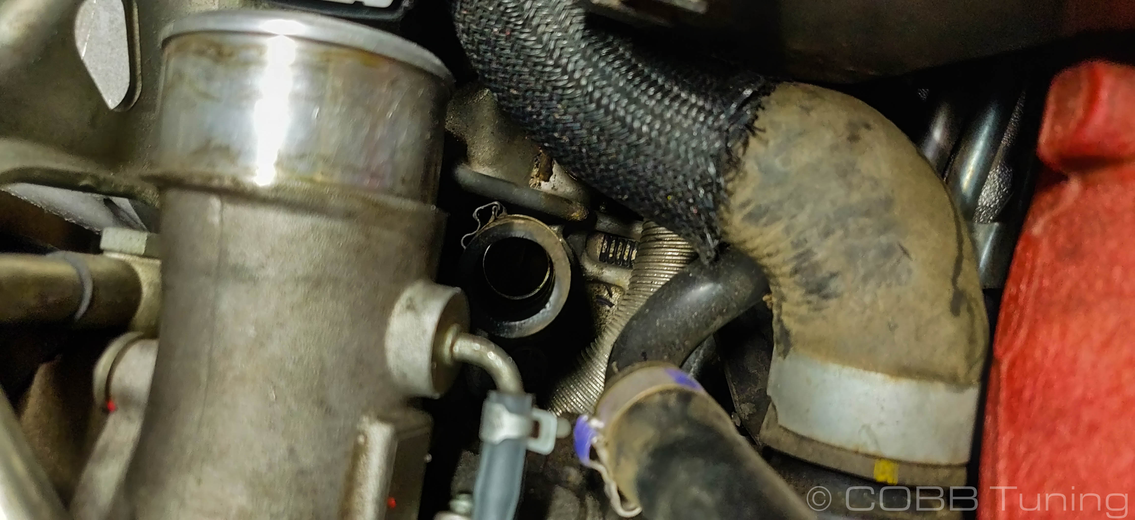
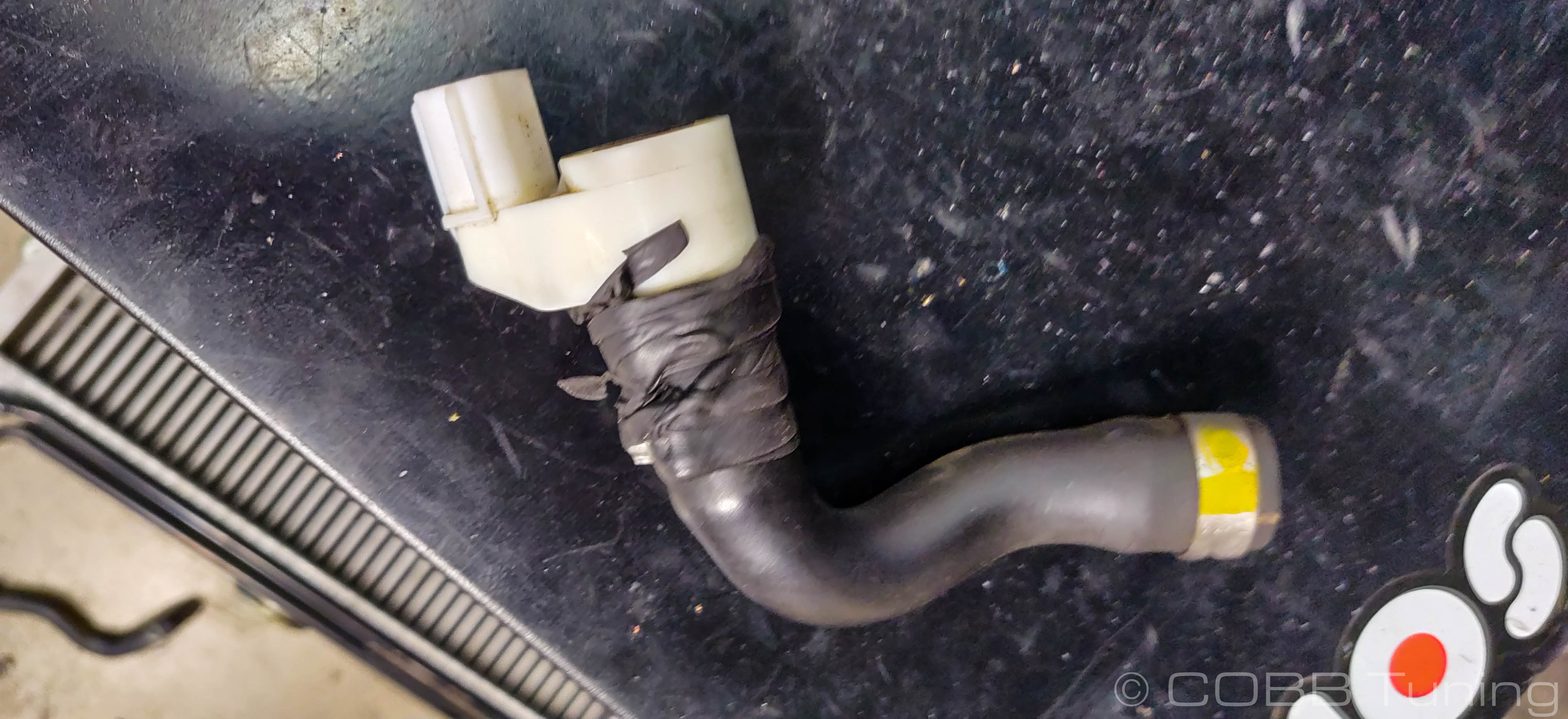
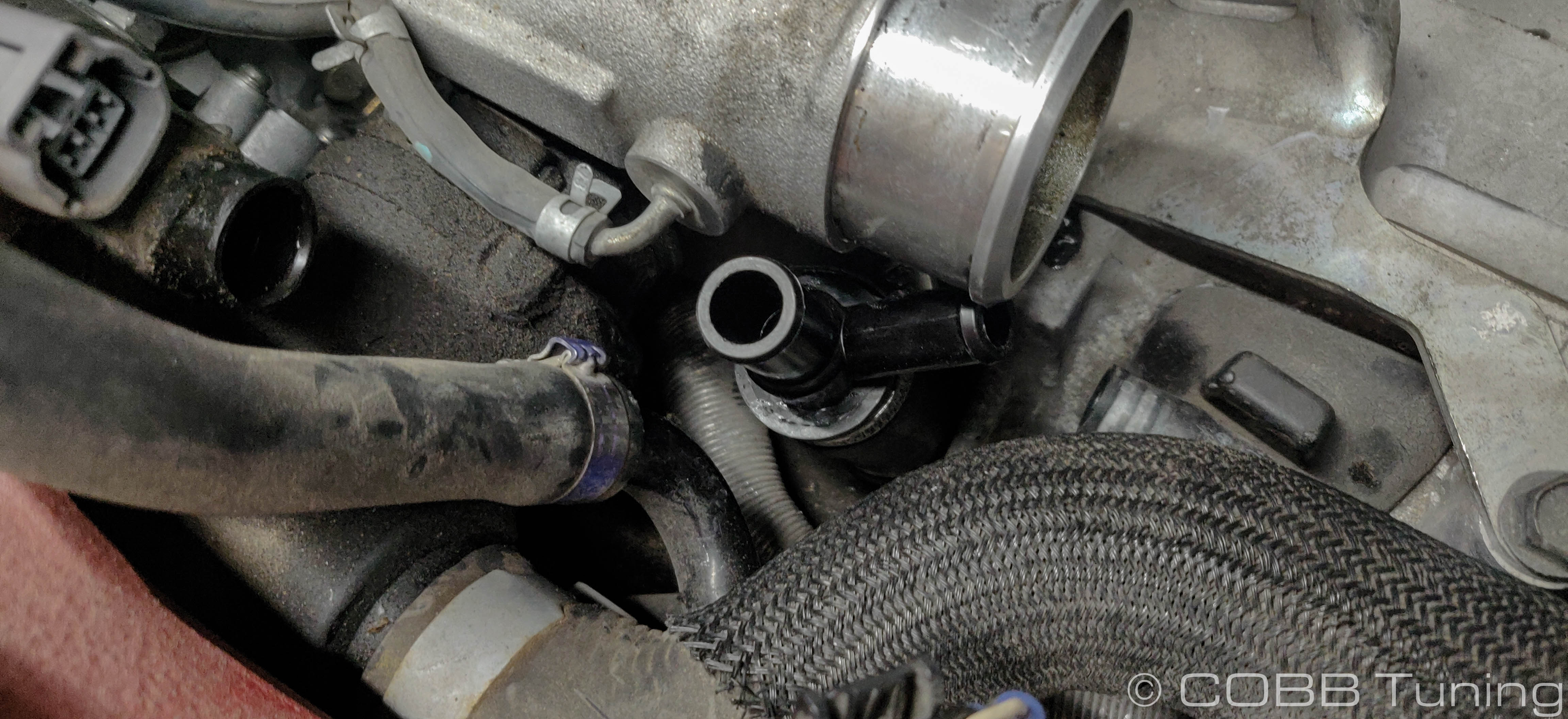
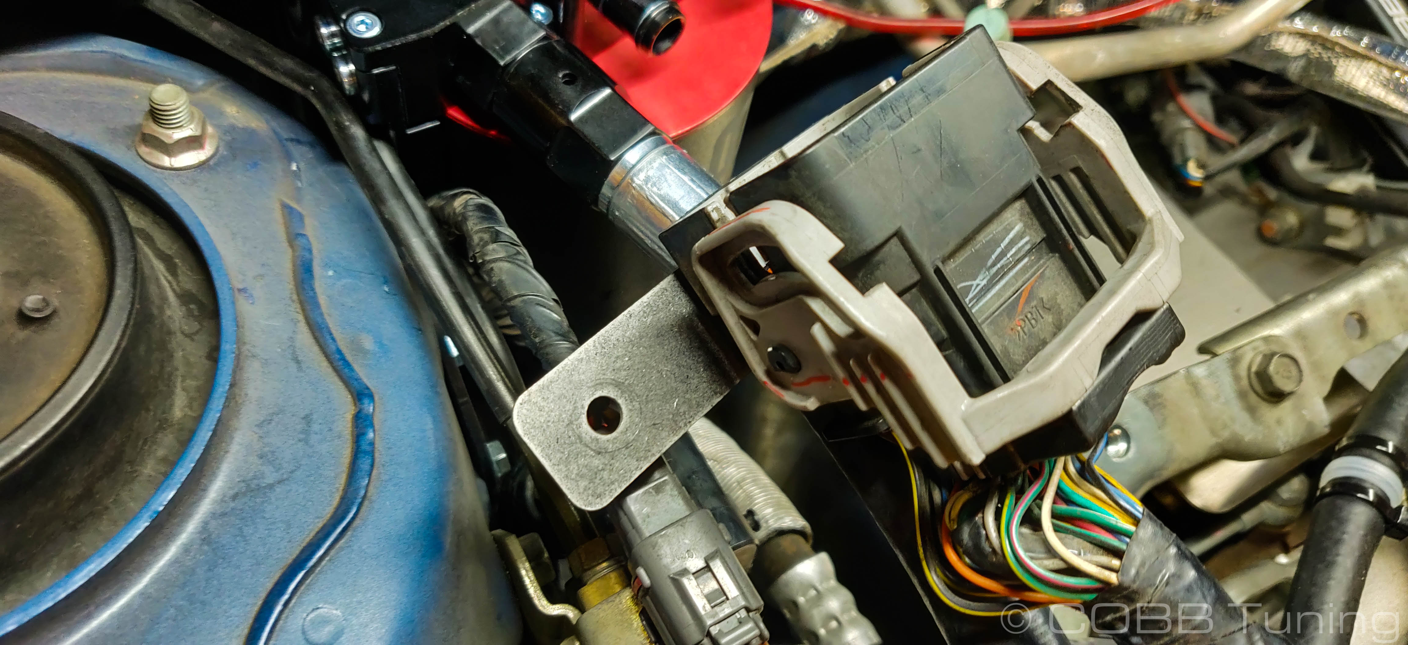
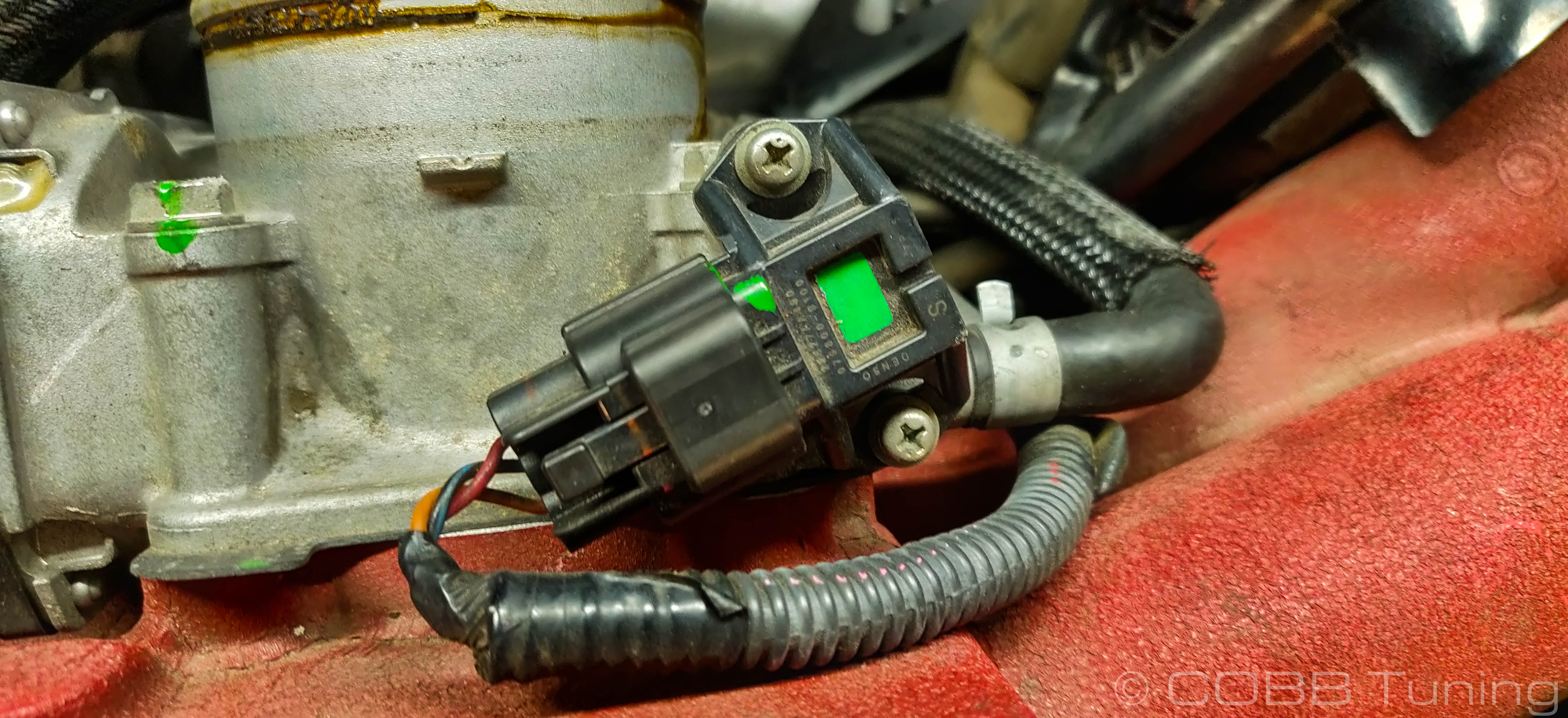
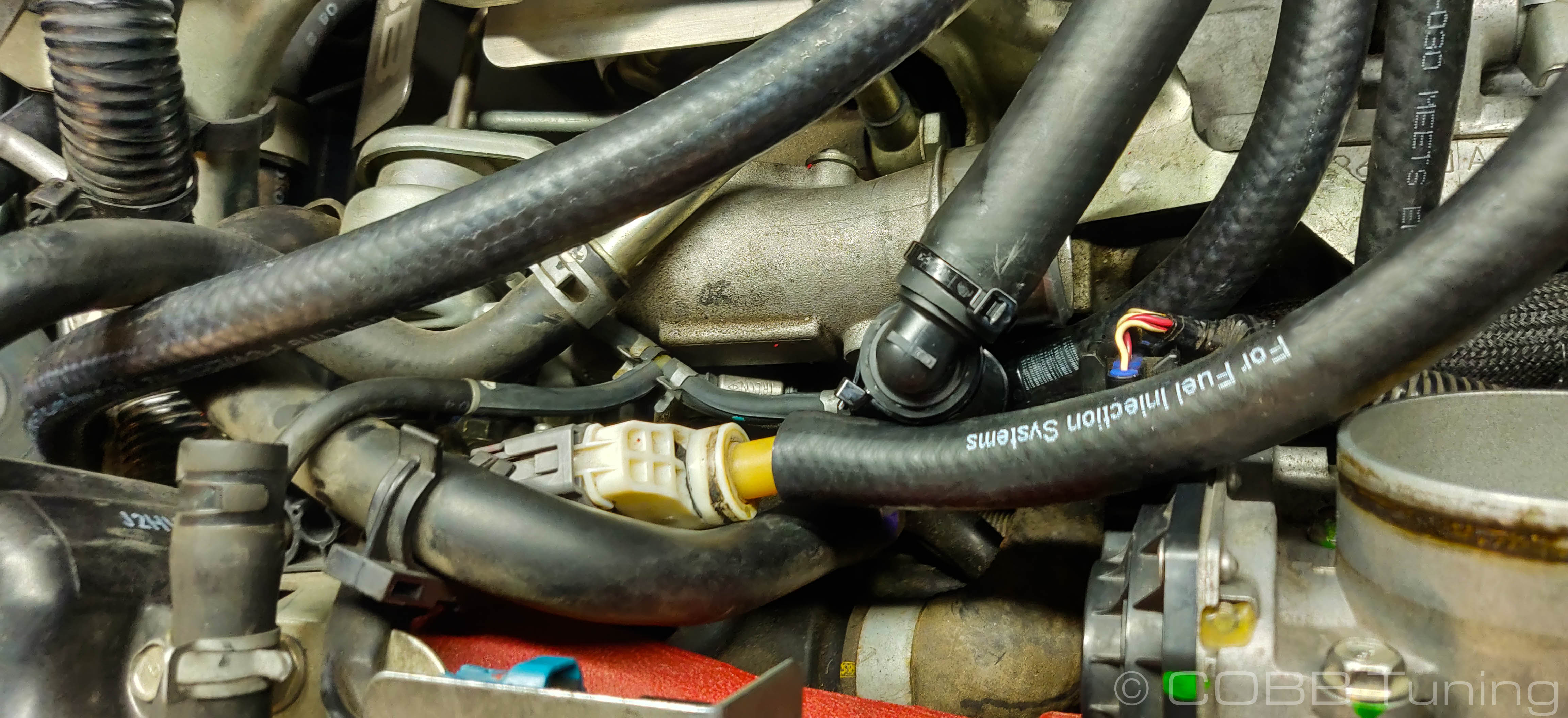
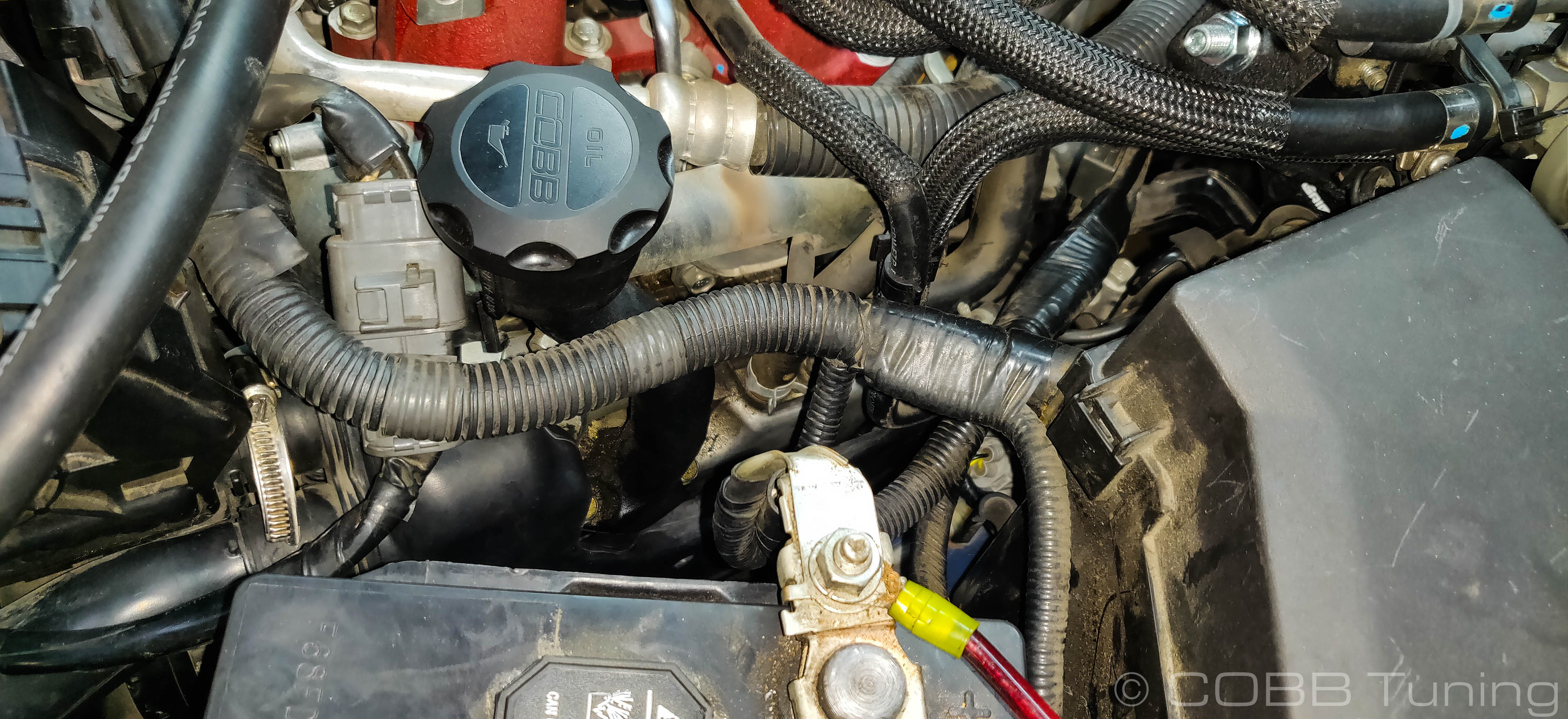
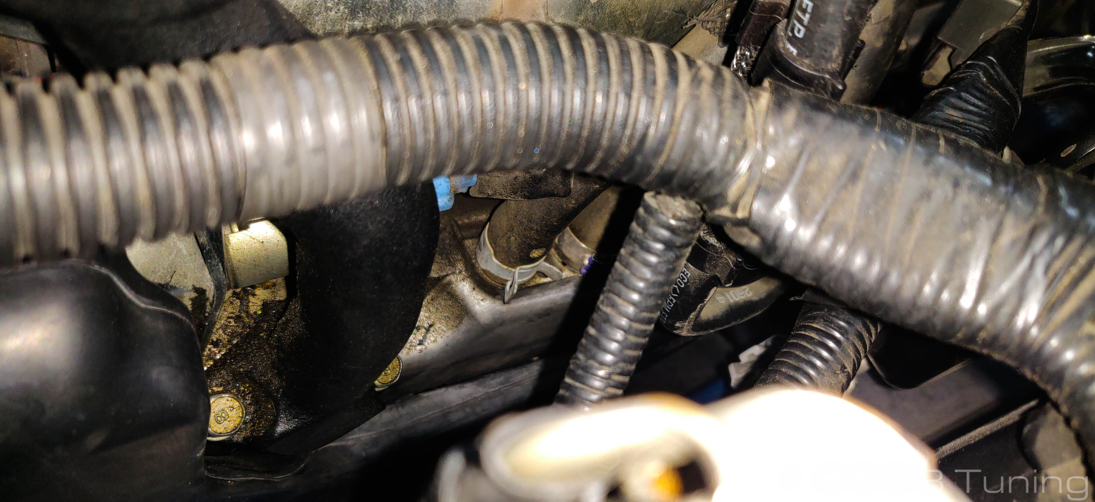
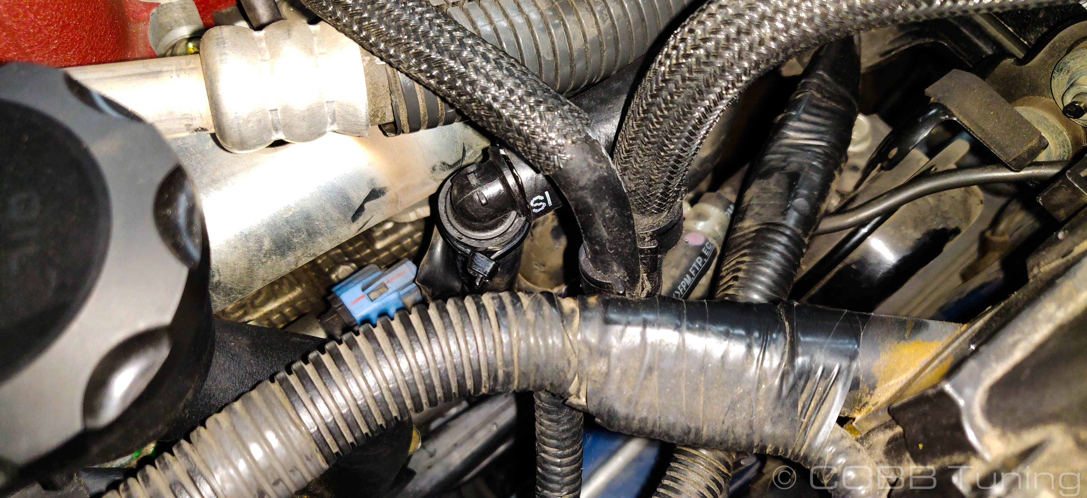
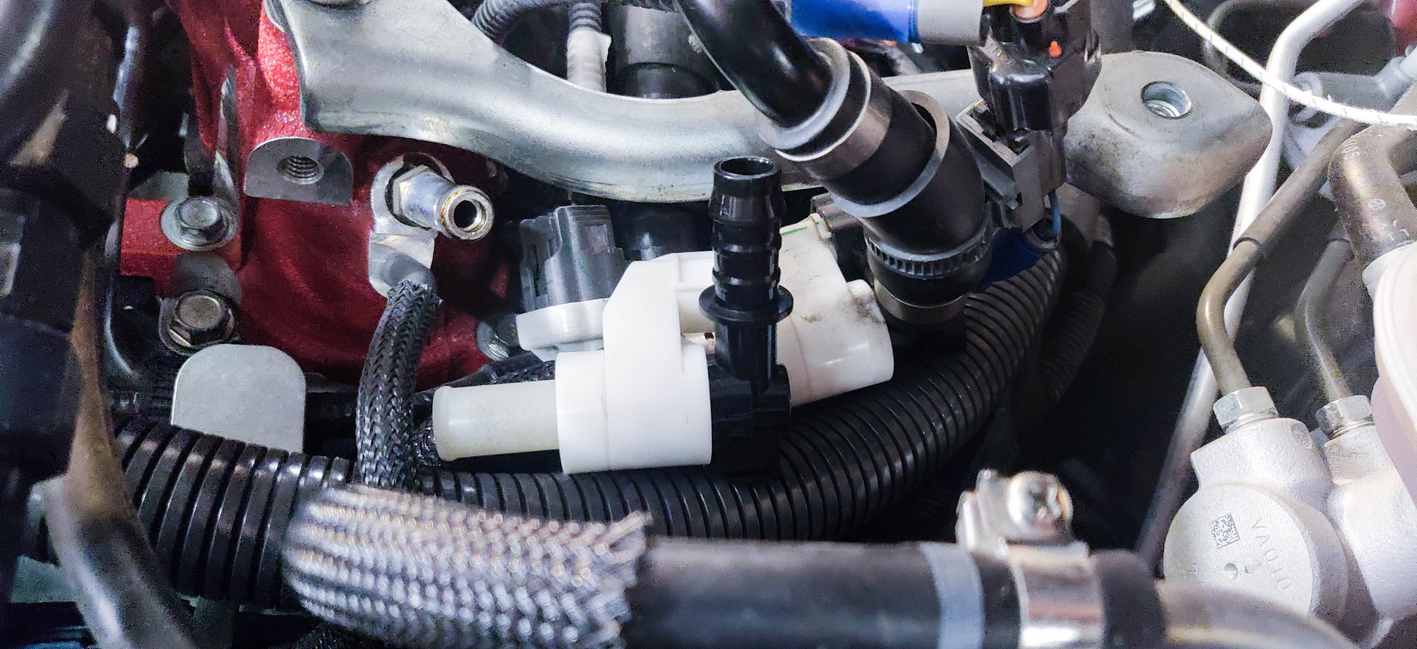
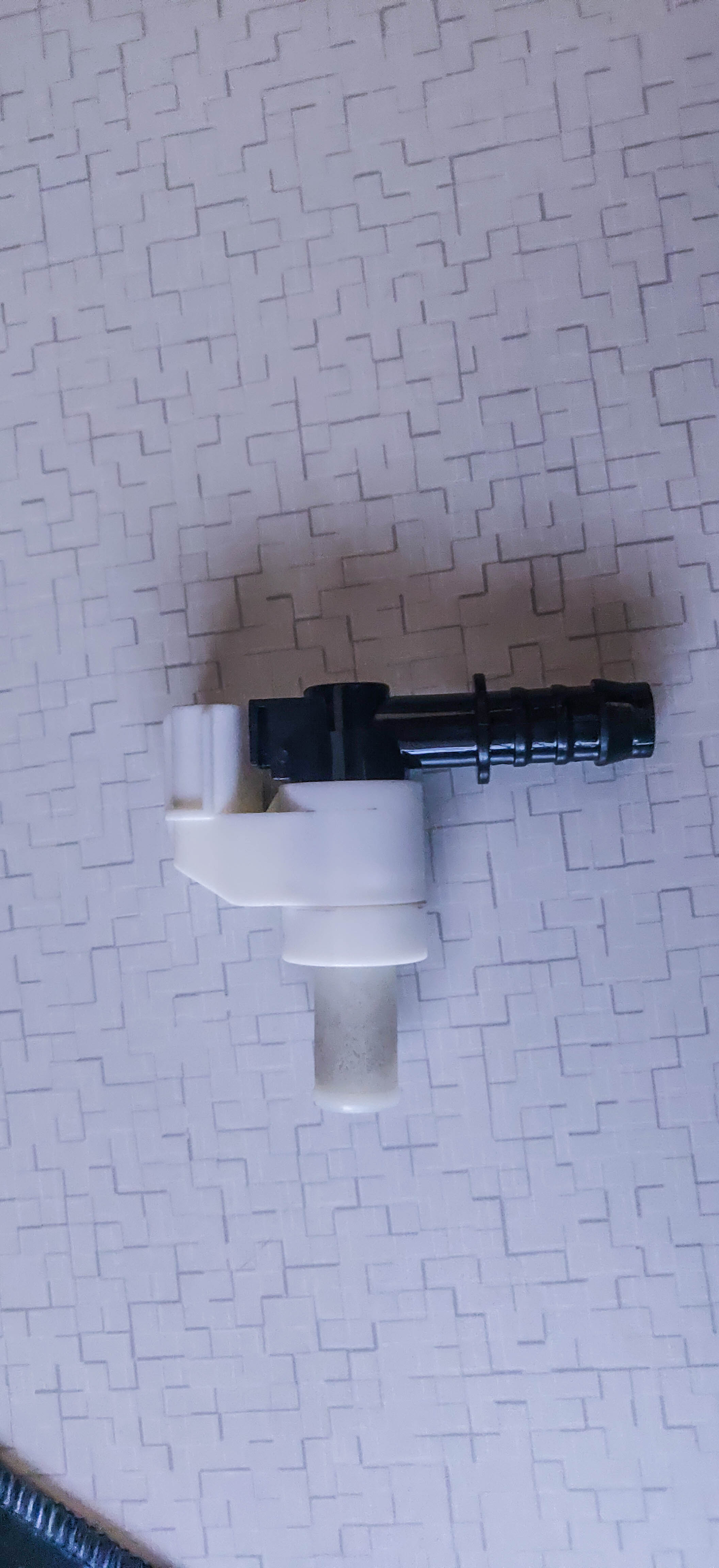
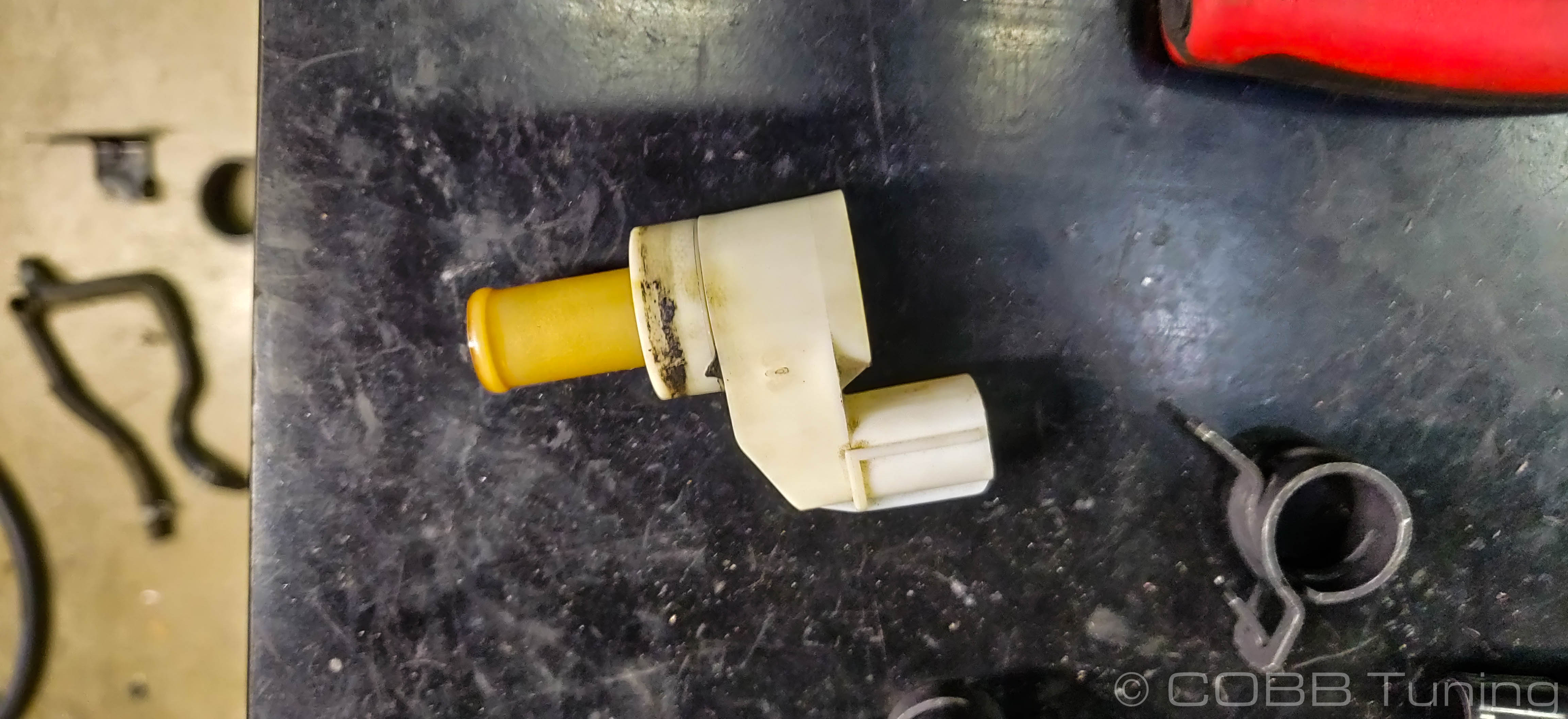
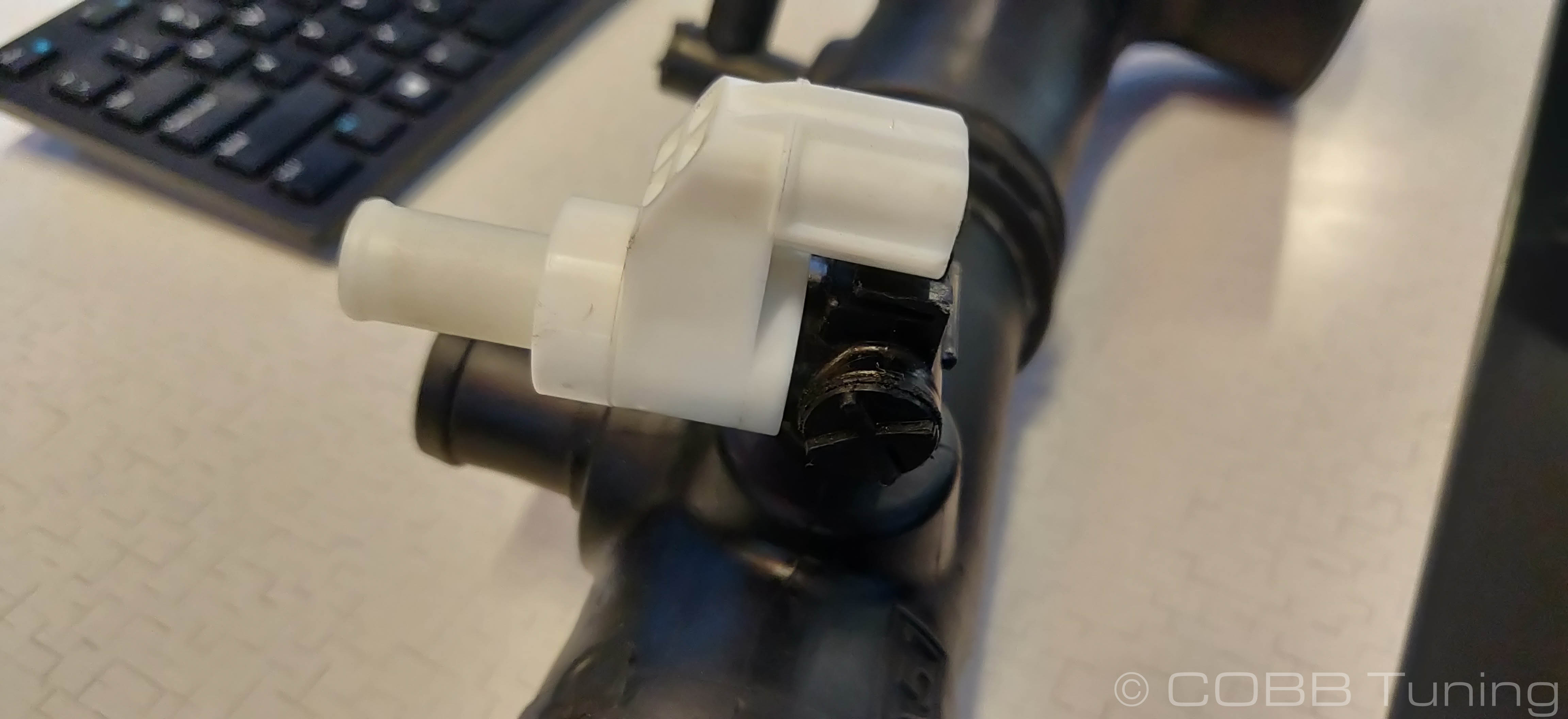
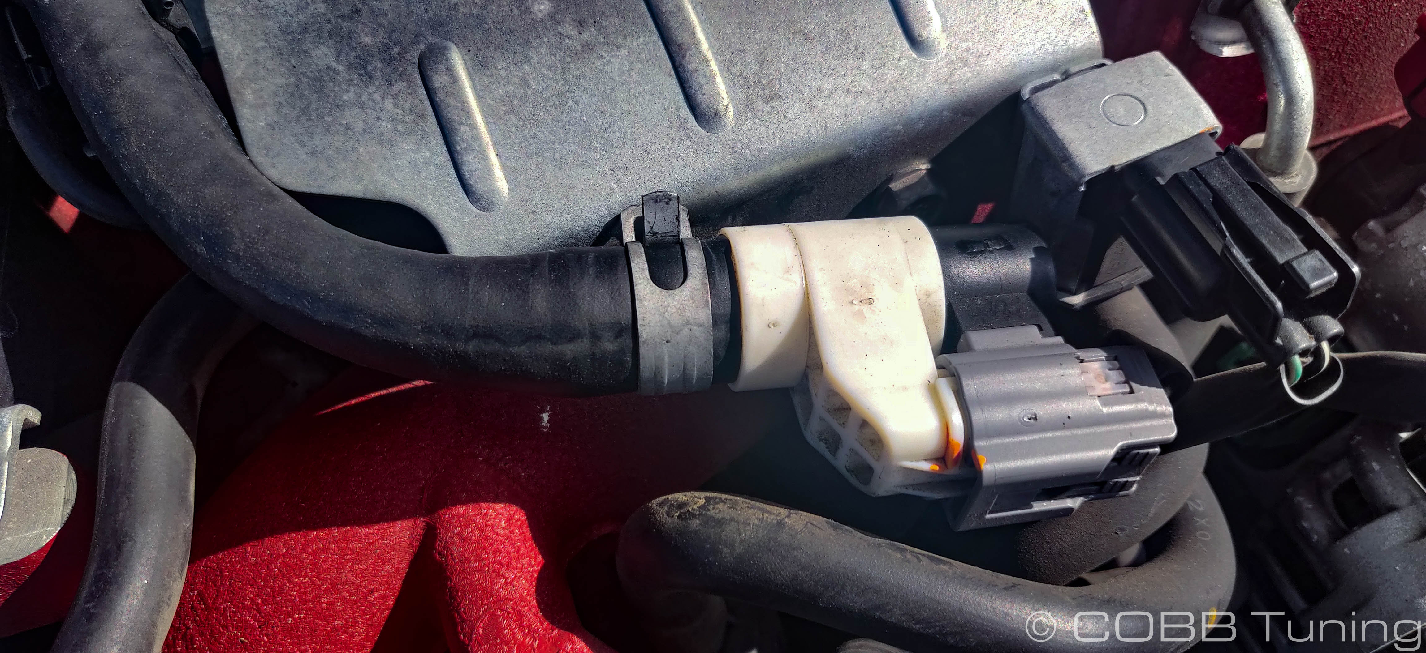
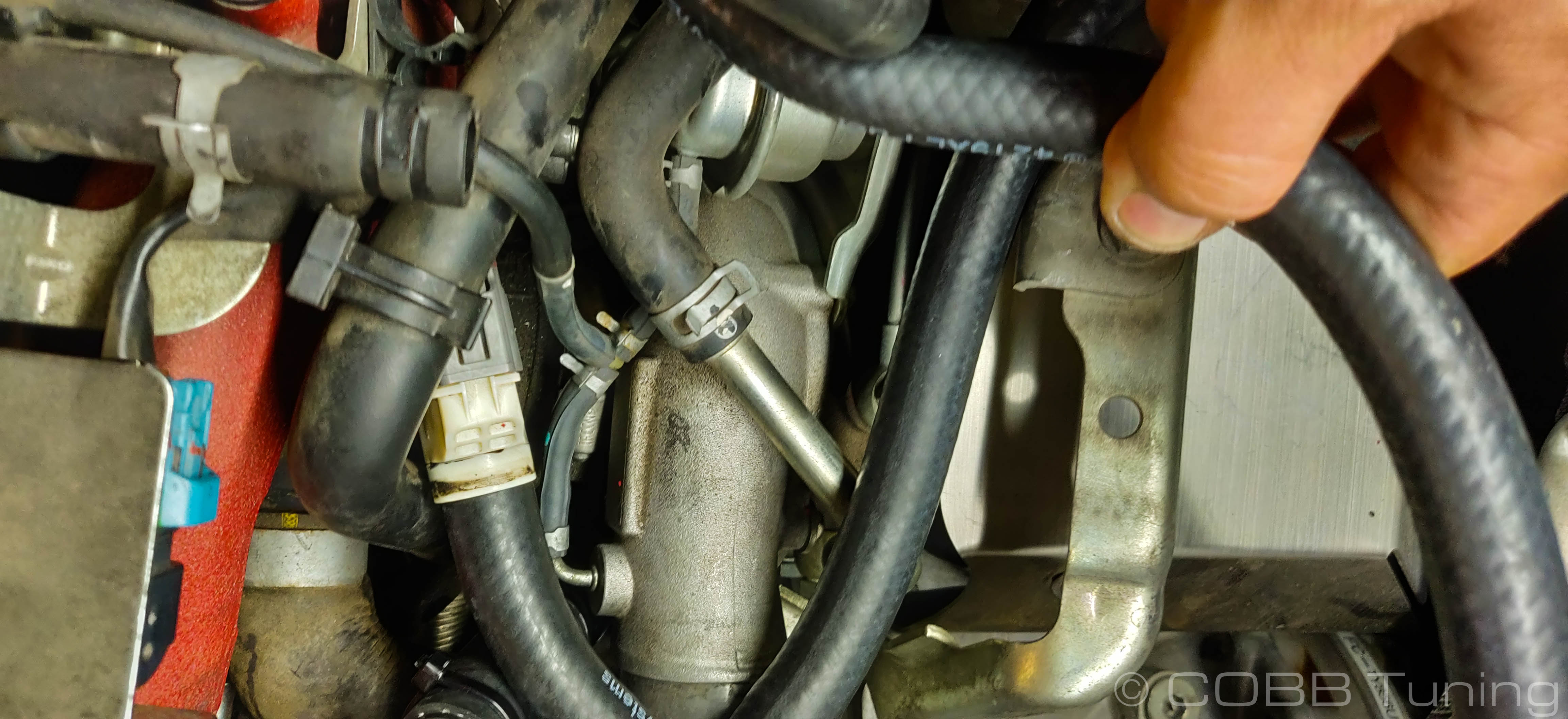
- Near the turbo you should see a 90 degree line coming up from the engine block and going into a white fitting, then the turbo inlet. (note the electrical tape to keep it from leaking which doesn't actually work for longer than about 10 seconds)
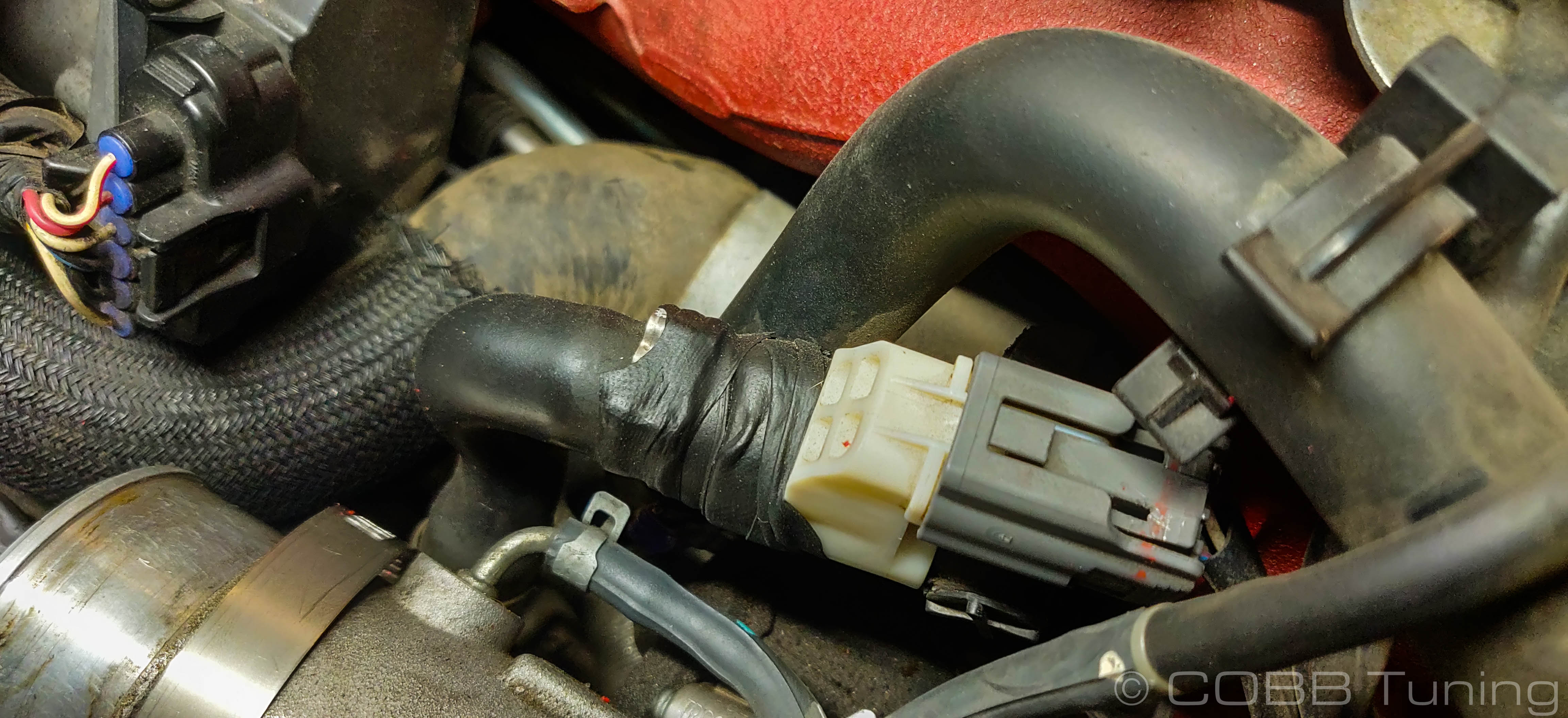
- The wiring connector does double-duty also holding the white sensor in place. Pressing down on the release tab pull outward gently to pop it out.
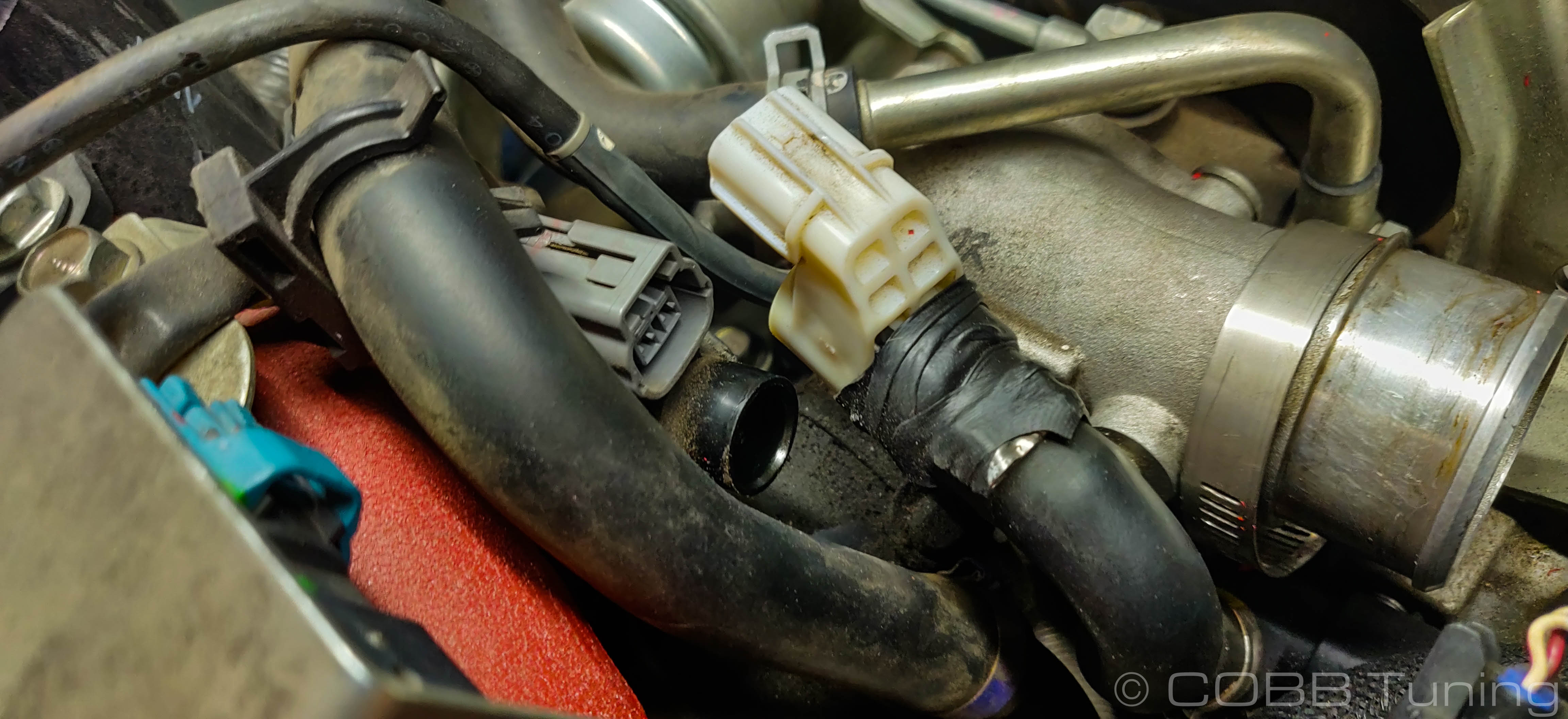
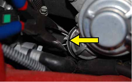
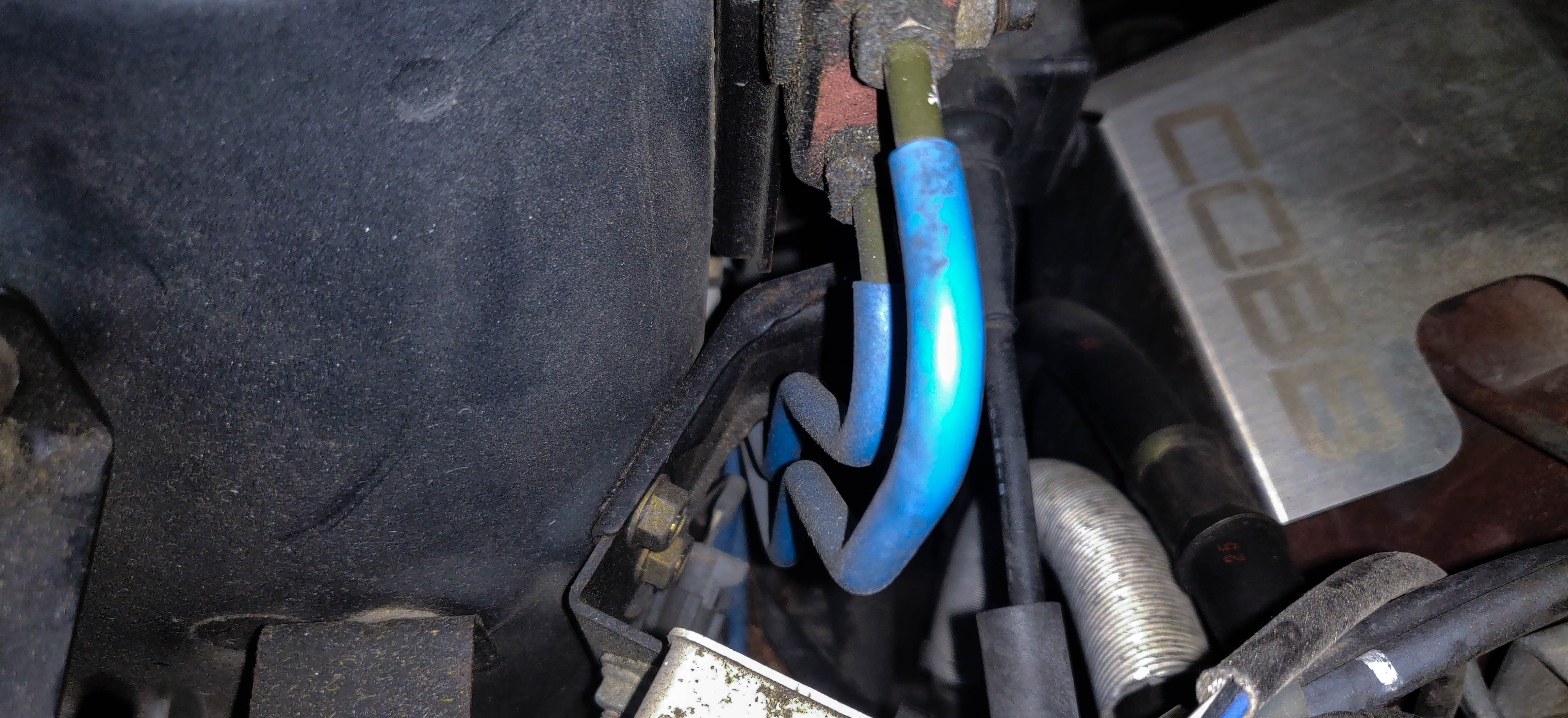
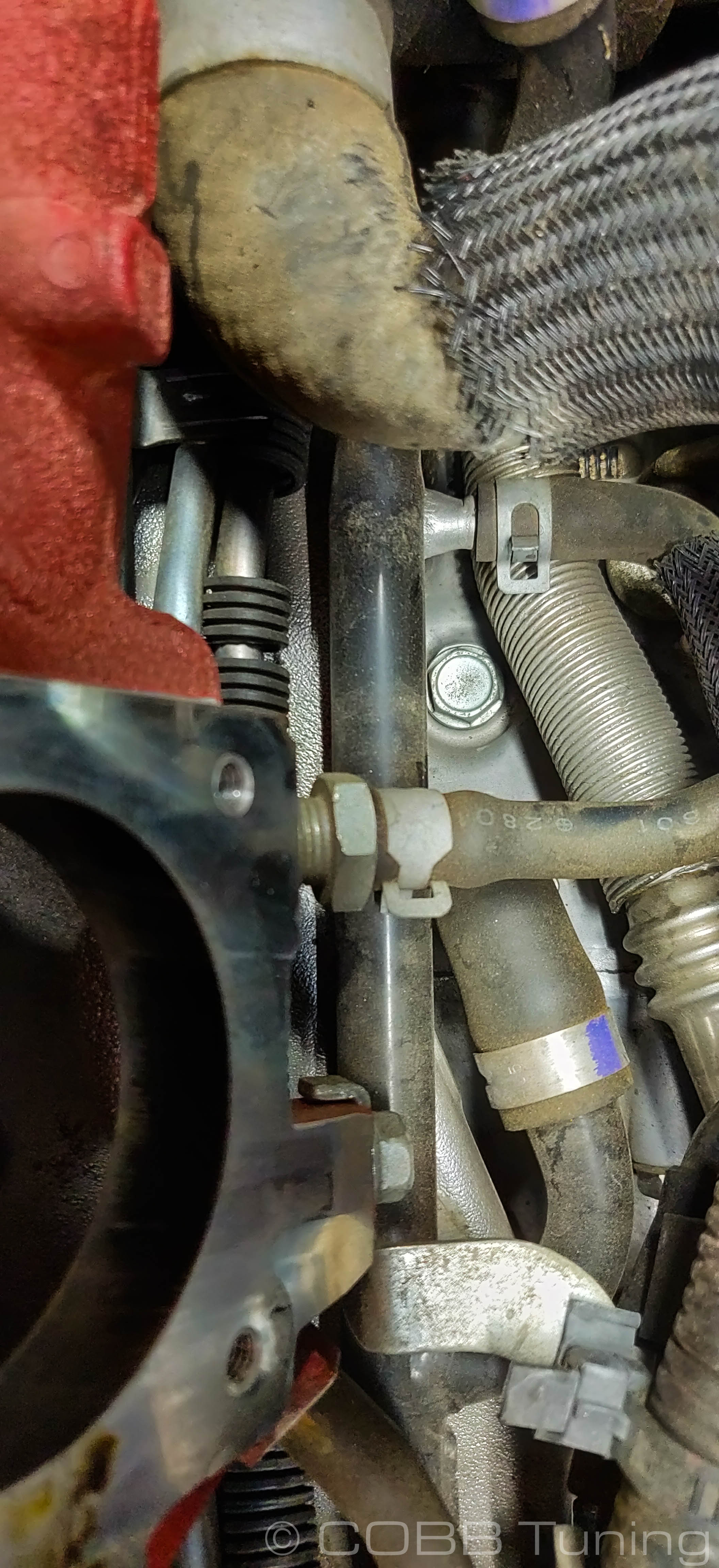
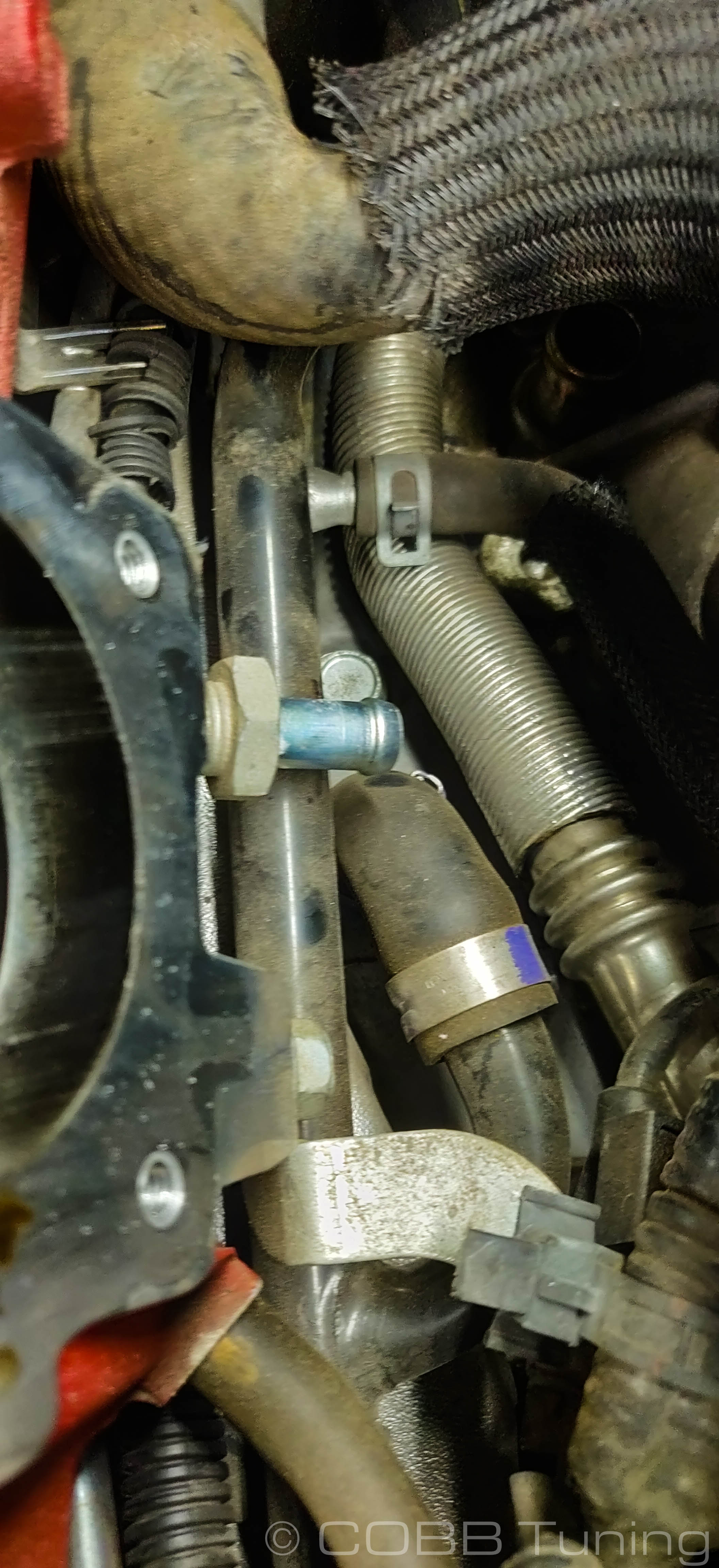
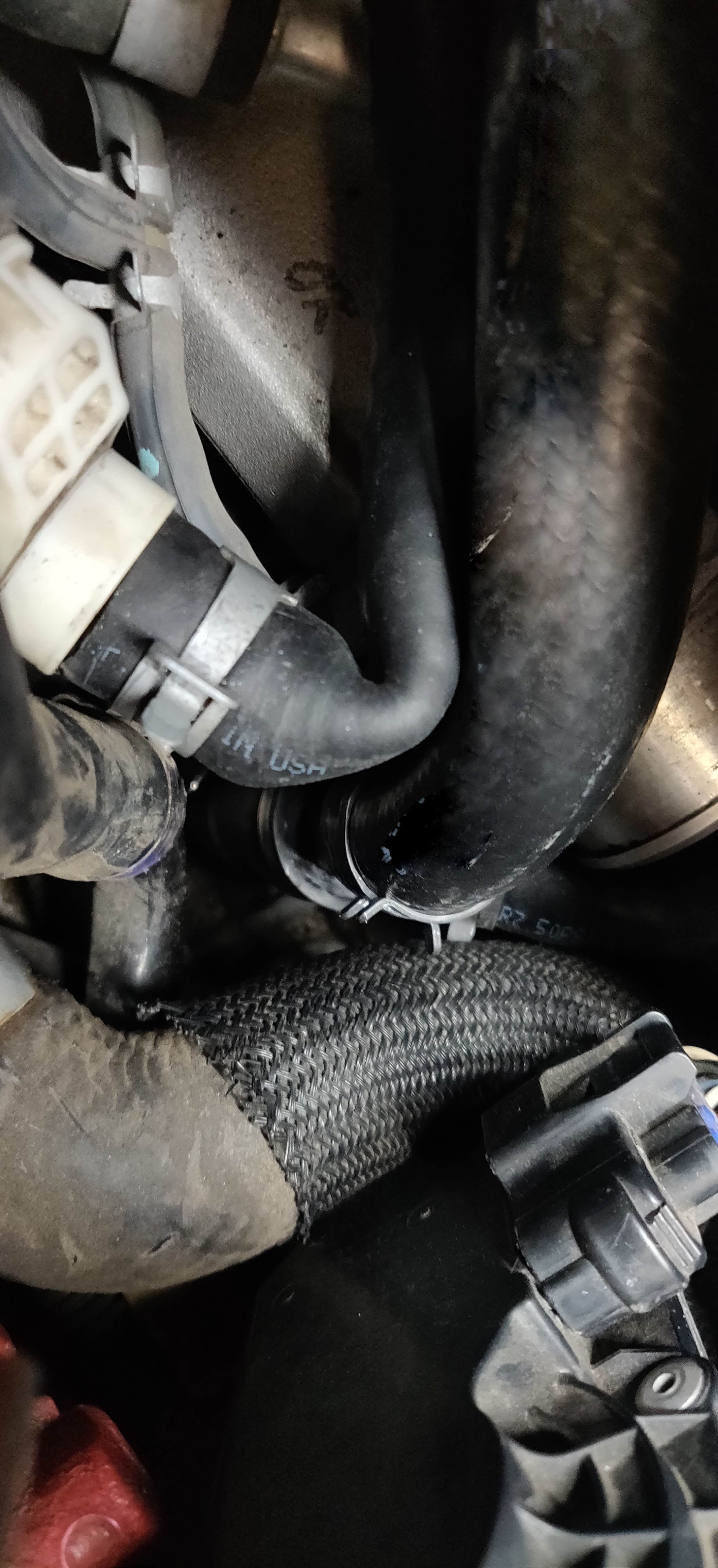
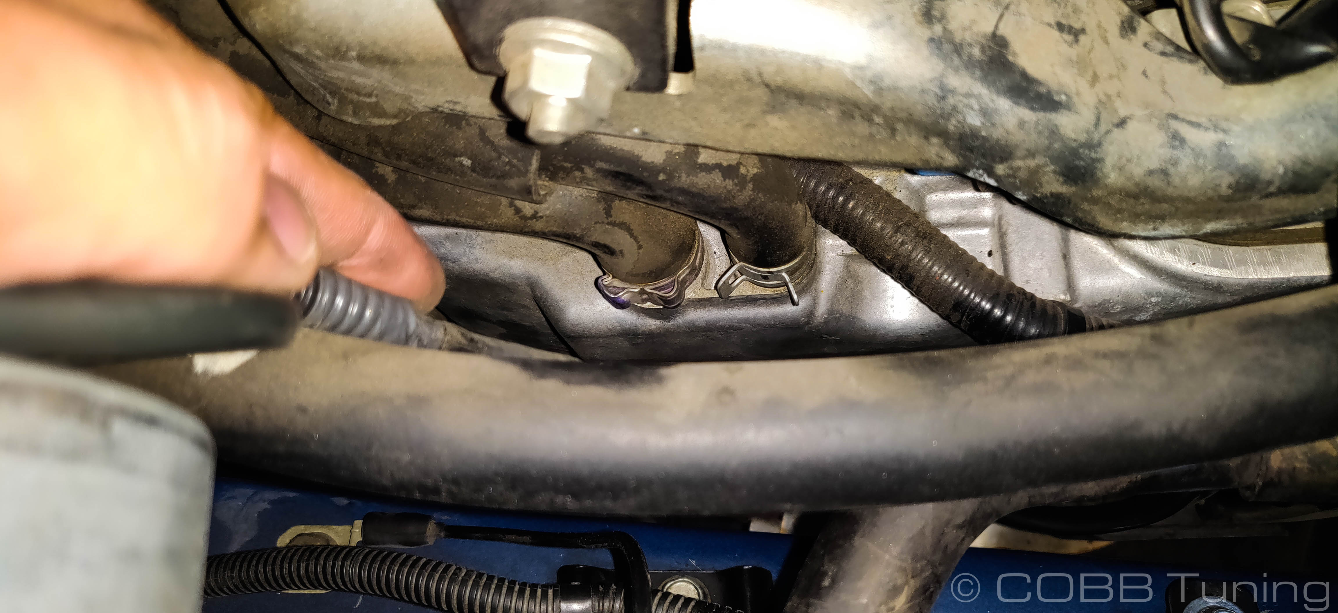
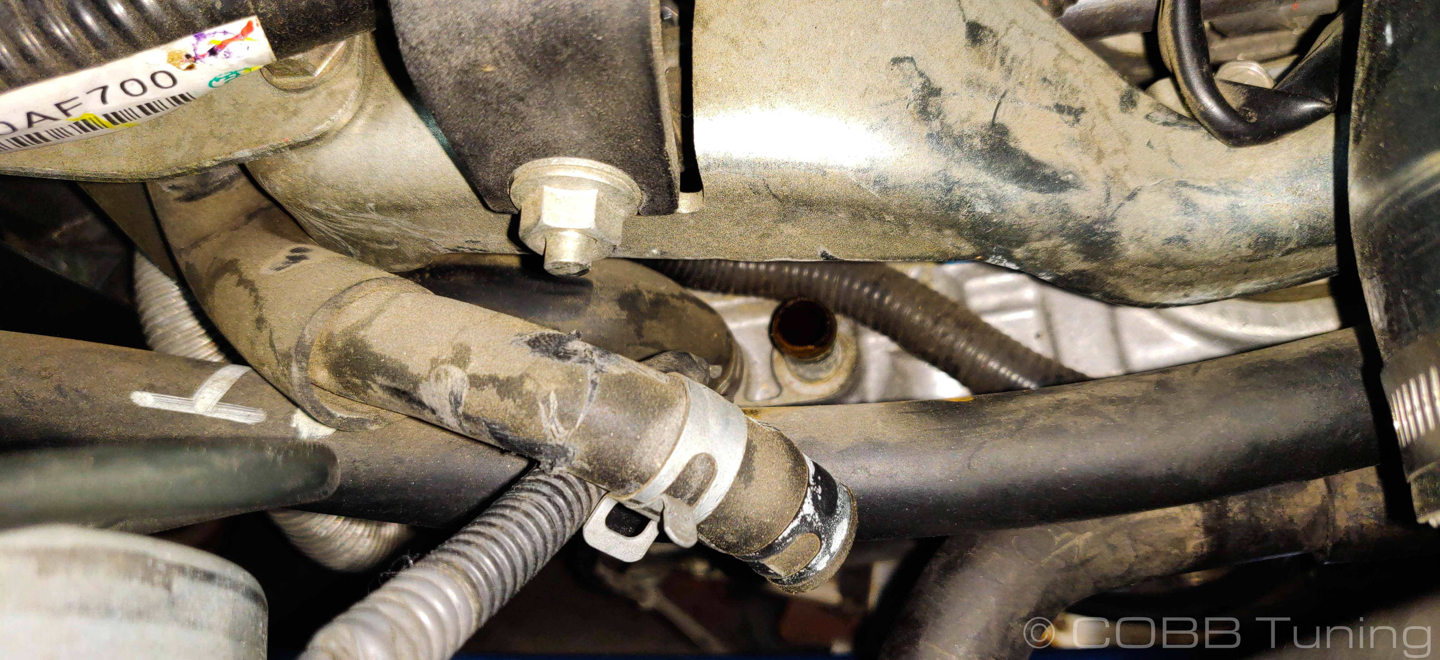
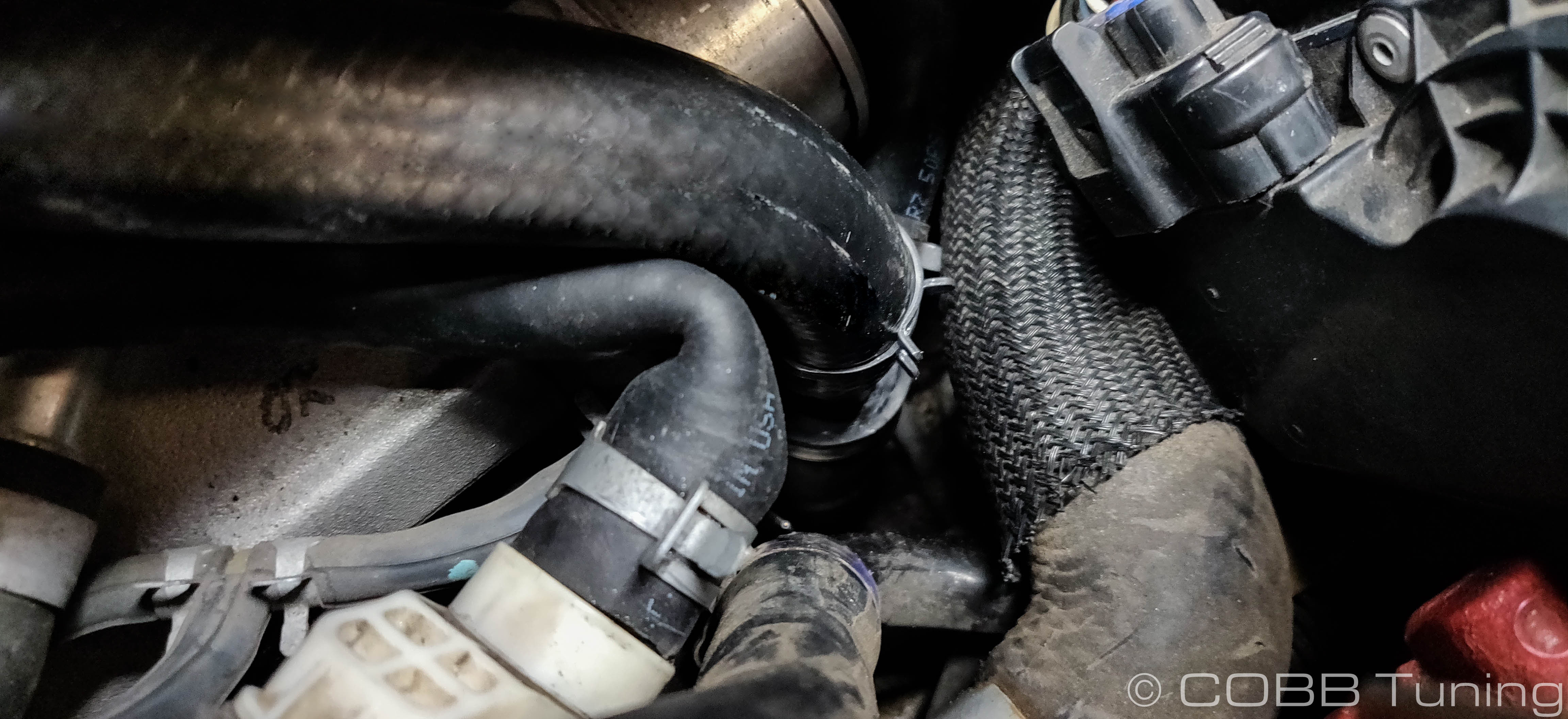
- Following that hose down, you should see a another line teeing off to a metal fitting and a smaller hose. Undo the hose clamp holding the smaller hose onto the pcv valve.
- With that line undone gently pull upward on the hose with the white connector, it should pop off of the crankcase breather / oil drain hose. Don't be afraid if it come off in individual pieces. The crimped metal clamps can be opened by inserting a small flat-blade screwdriver and gently turning it to bend the clamp open.
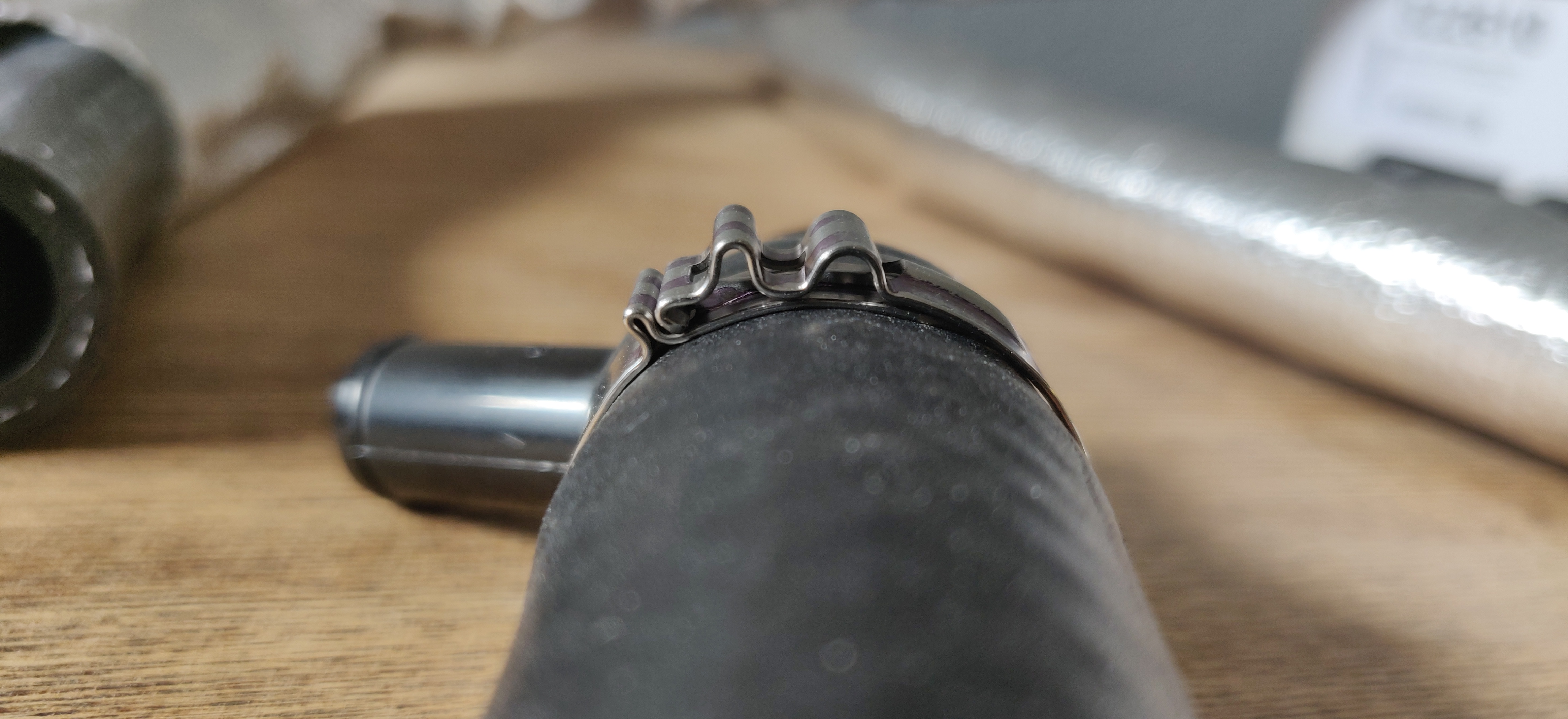
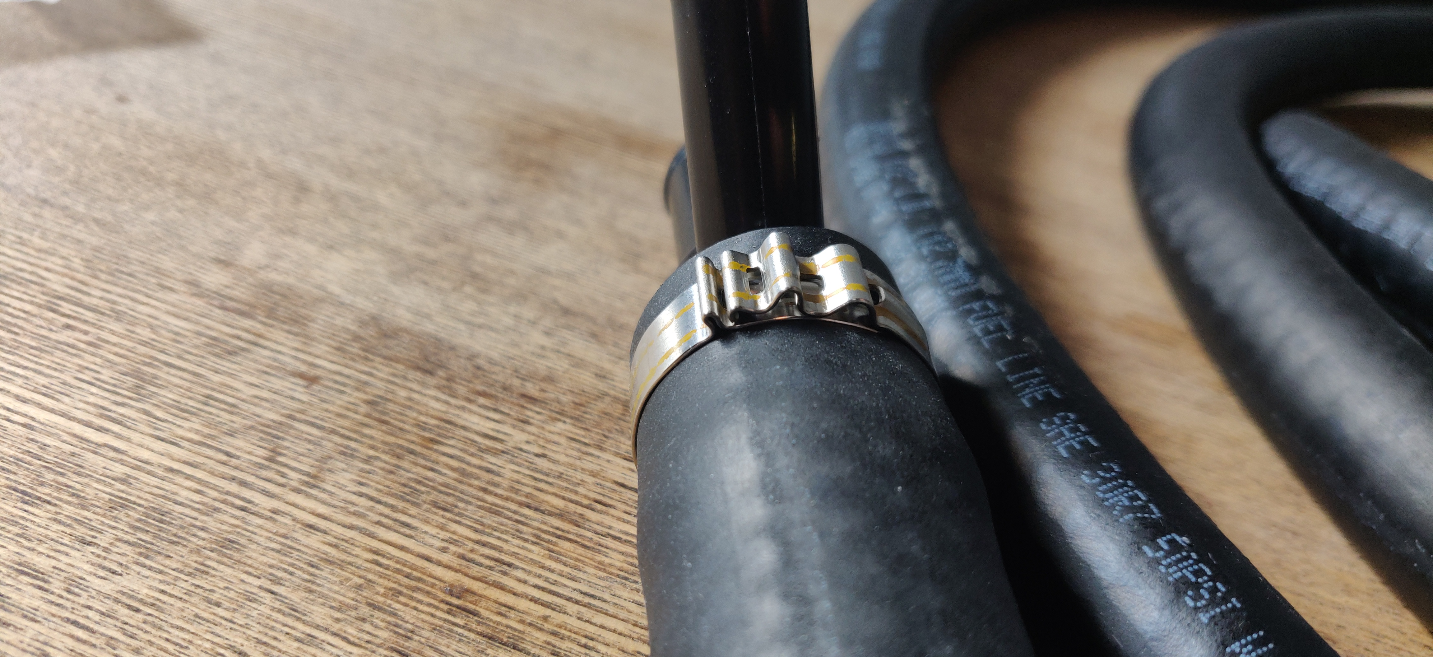
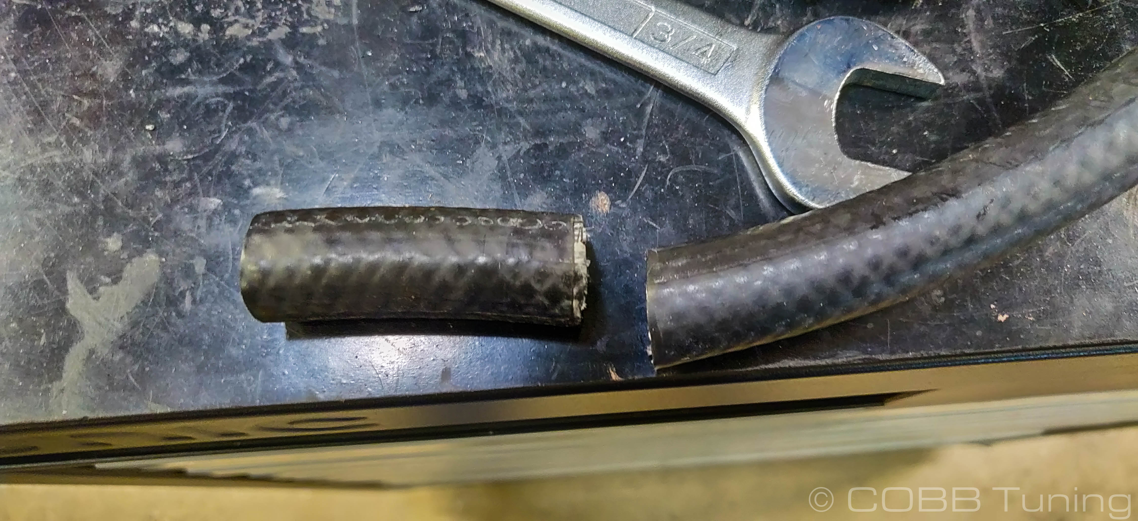
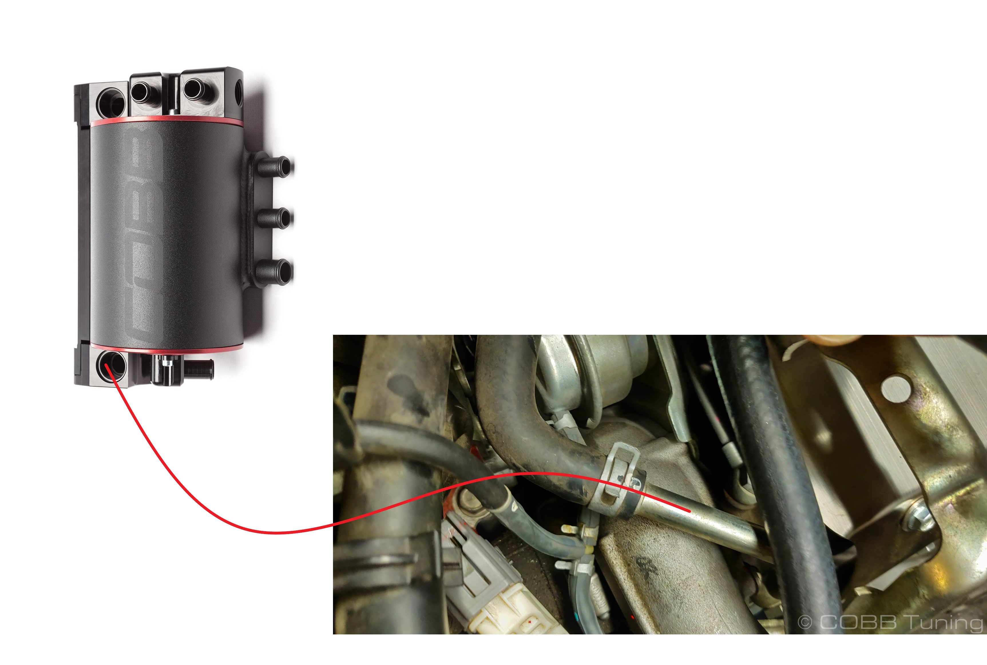
- Take the provided 5/8" drain line and install it onto the larger side of the plastic y-fitting that was provided. Secure it with one of the provided clip clamps by simply pushing the clamp together with a pair of pliers. until it buts up against the raised portion on the bottom piece. DO NOT GO OVER THE HUMP
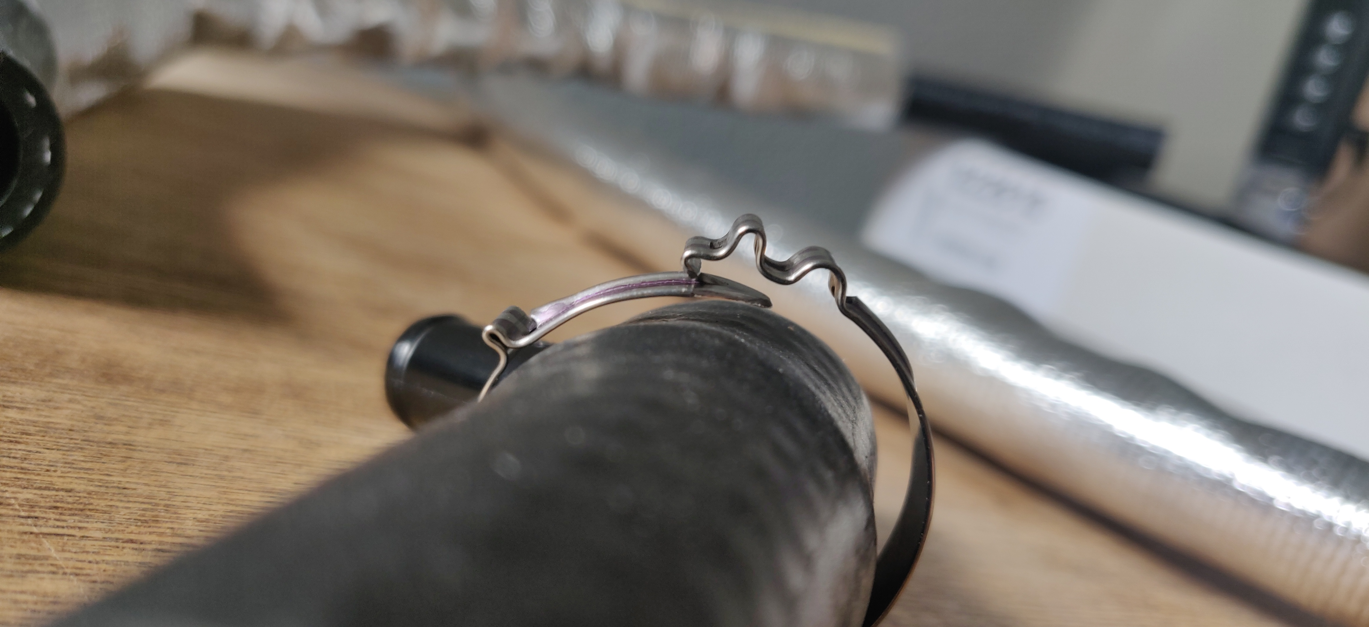
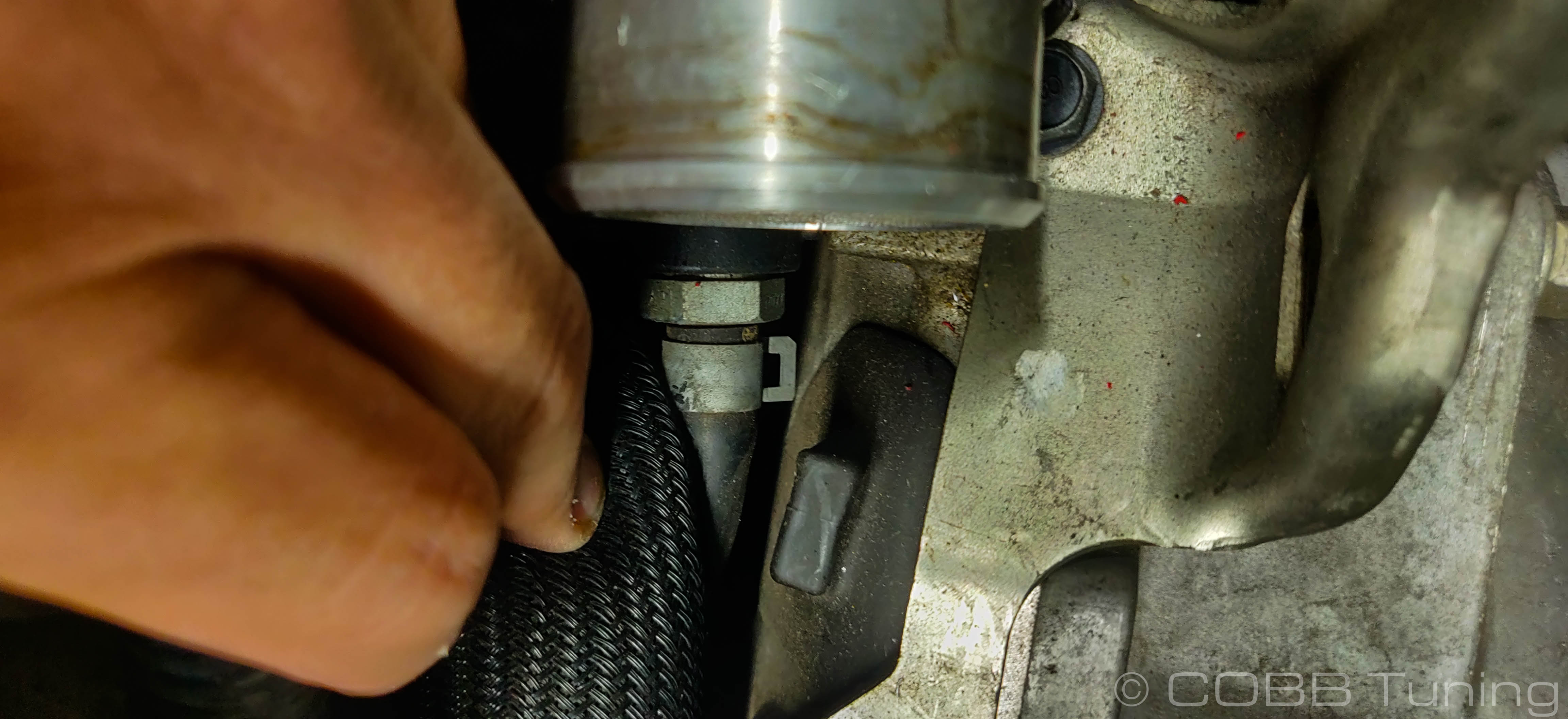
- Using the same method and clamp style, attach the oil drain back to the drain line on the block. If the fitting appears slightly loose you can squeeze the looped portion of the clamp lightly with some pliers to tighten it up.
If you need to remove the clamps for any reason you can use a small screwdriver in this area pushing lightly down and outward to pop the clamp free.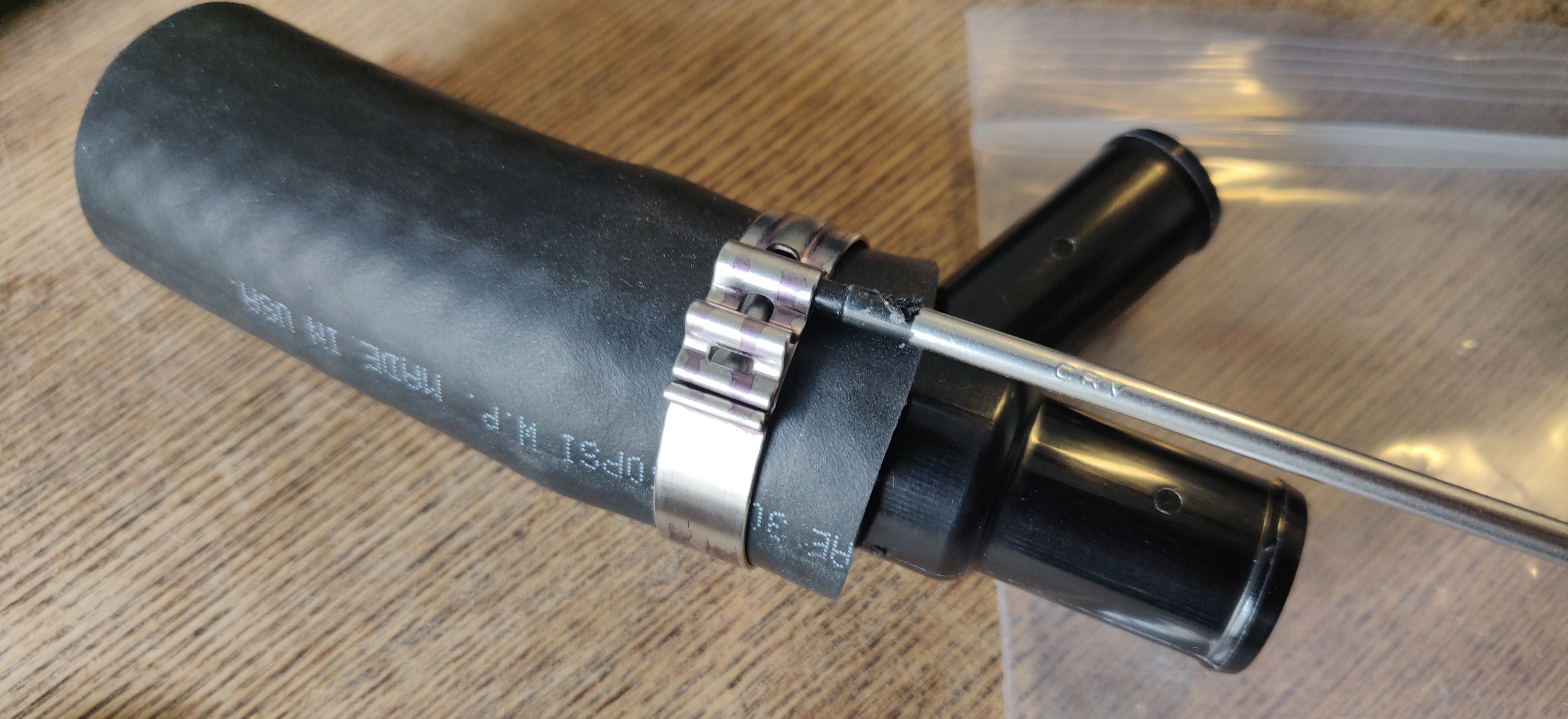
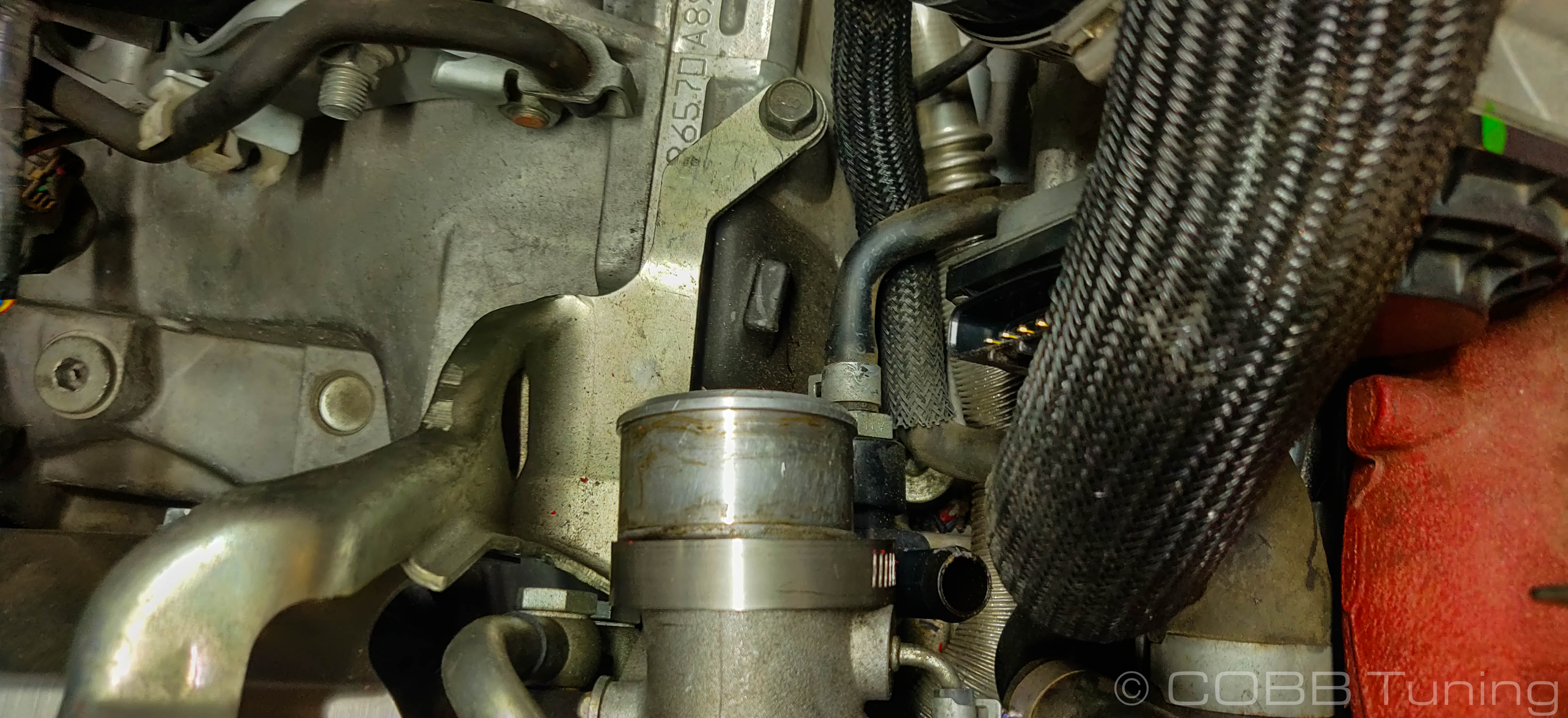
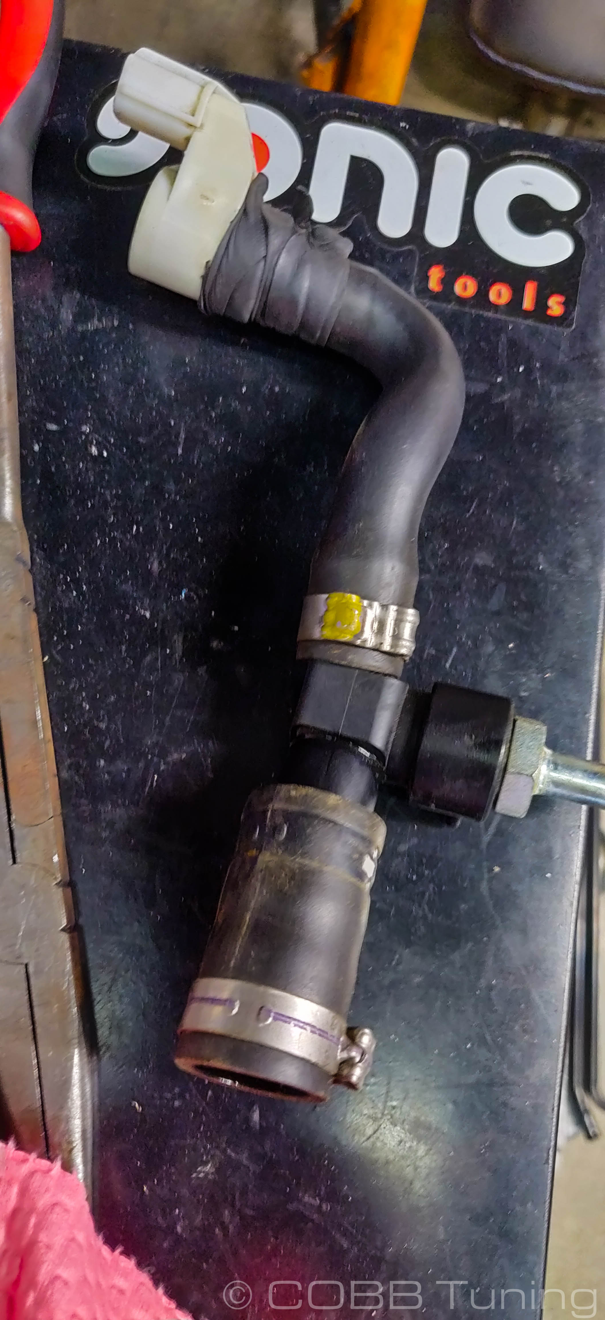
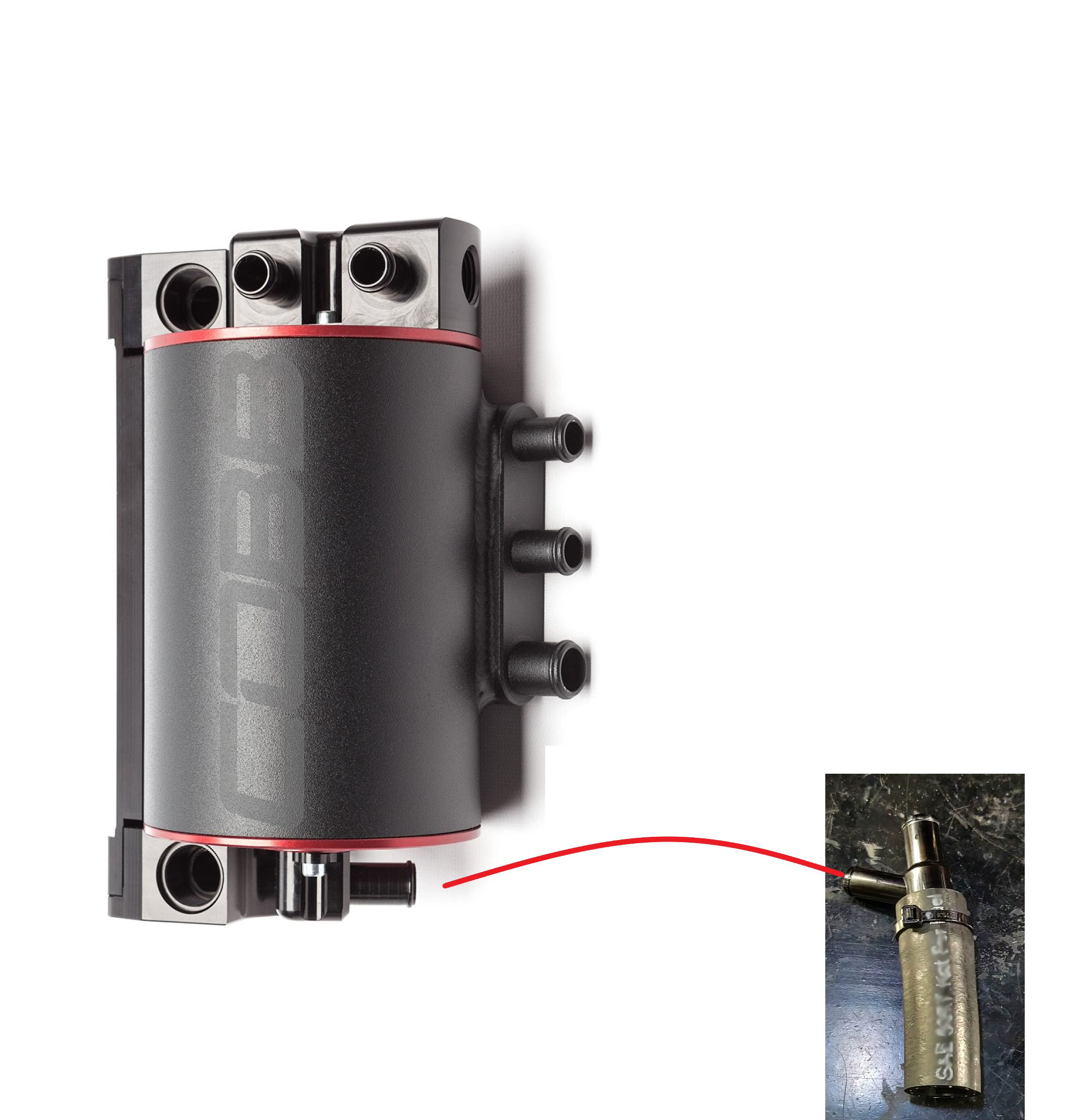
This assembly essentially replaces the drain and tee from this assembly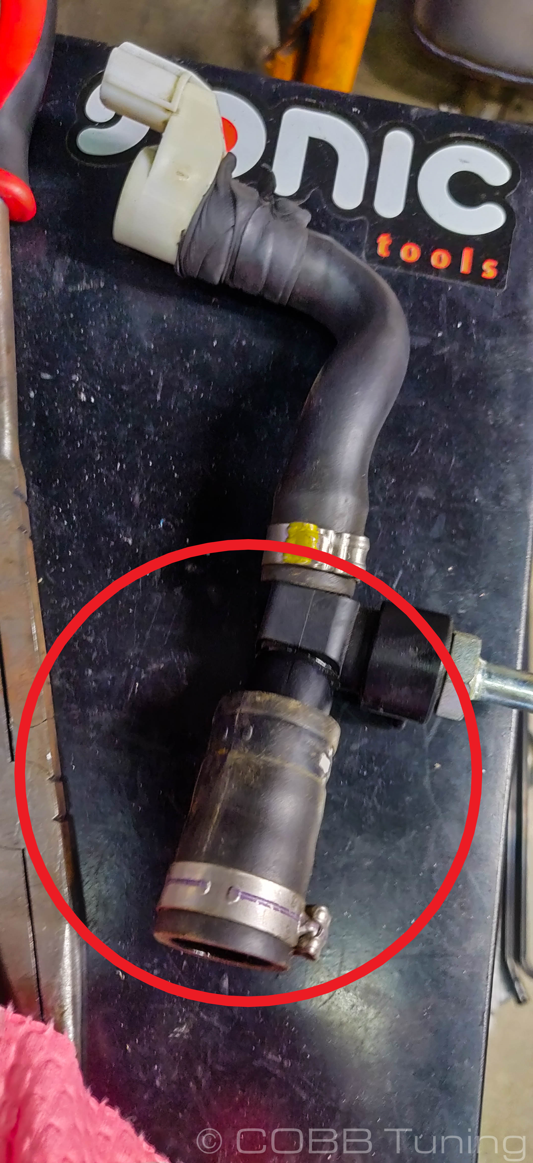
AOS Pre-Assembly
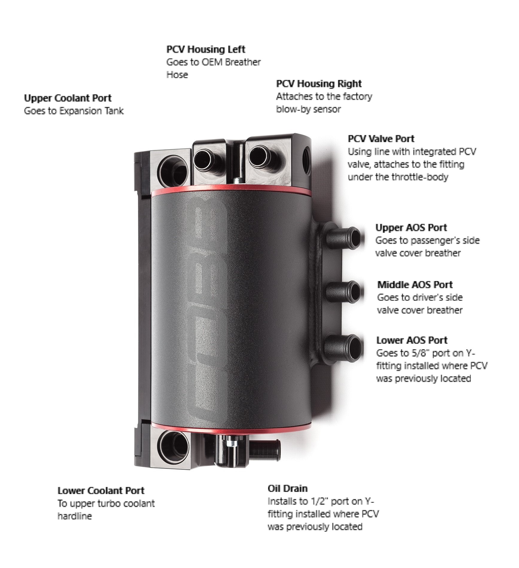
- Install the upper coolant line (With the extended fitting for air bleeding) to the top of the AOS, it should have two ports rather than the single one for the drain line. Gently snug it in place (being careful not to crush the o-ring) with a -8 AN wrench.
- Add the lower coolant hose to the opposite end as well. Gently snug it in place (being careful not to crush the o-ring) with a -8 AN wrench.
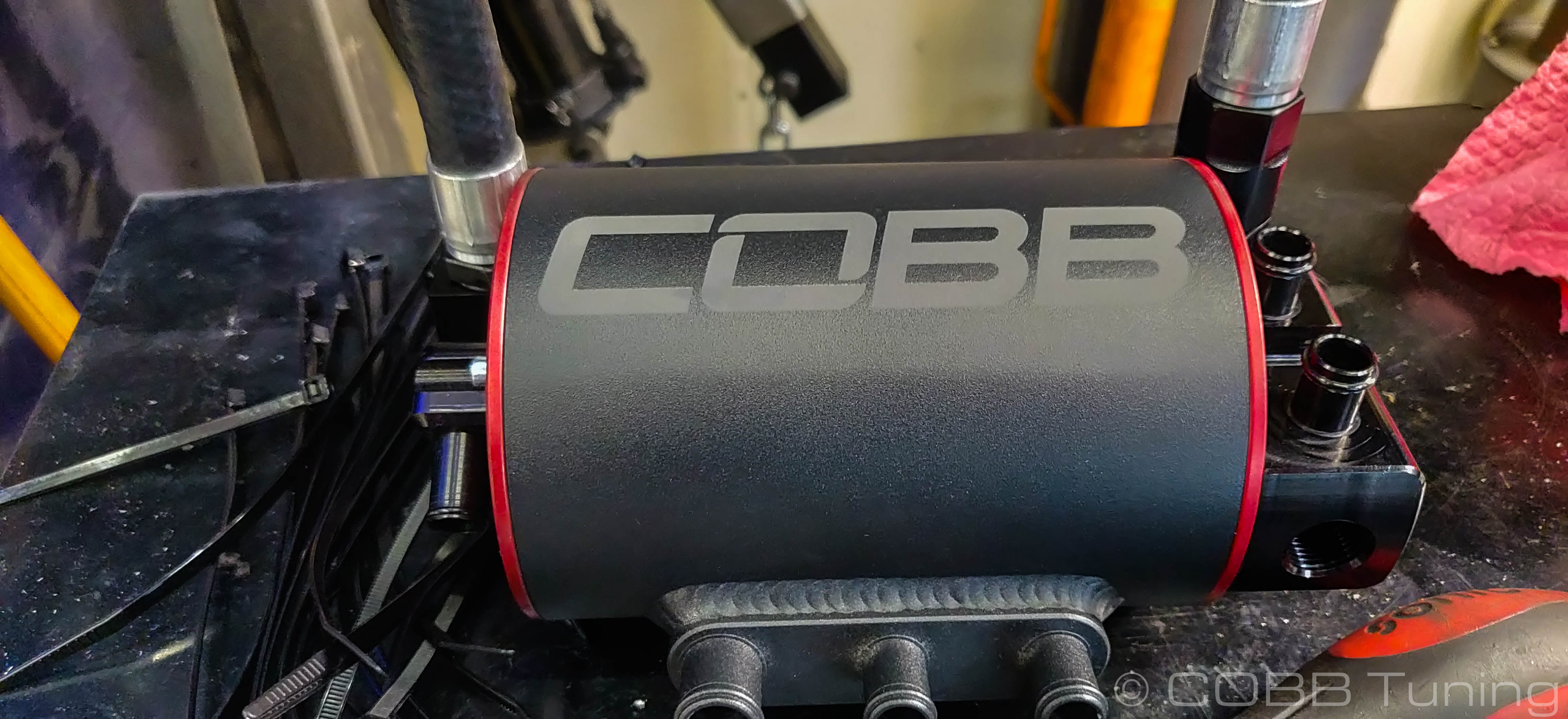
- At the end of the PCV housing on the top of the AOS there is a threaded hole. Install the PCV hose with integrated PCV valve into this fitting. Use teflon tape to ensure there are no air leaks. Make sure there are spring clamps in place on each hose junction.
- Install the provided bracket onto the AOS. Typical mounting is one hole below the top for GR vehicles 08+ or all the way at the bottom for GD vehicles (02-07), however on this car and some others, the firewall bends out and hits the top. We recommend test fitting it a few times by lining it up with the bolt holes from the harness bracket. Adjust your height and test fit as needed to ensure nothing is causing issues either on the top or the bottom. Tighten the three Allen bolts using a 5mm allen wrench or socket. Keep in mind the bend should face dowward.
GD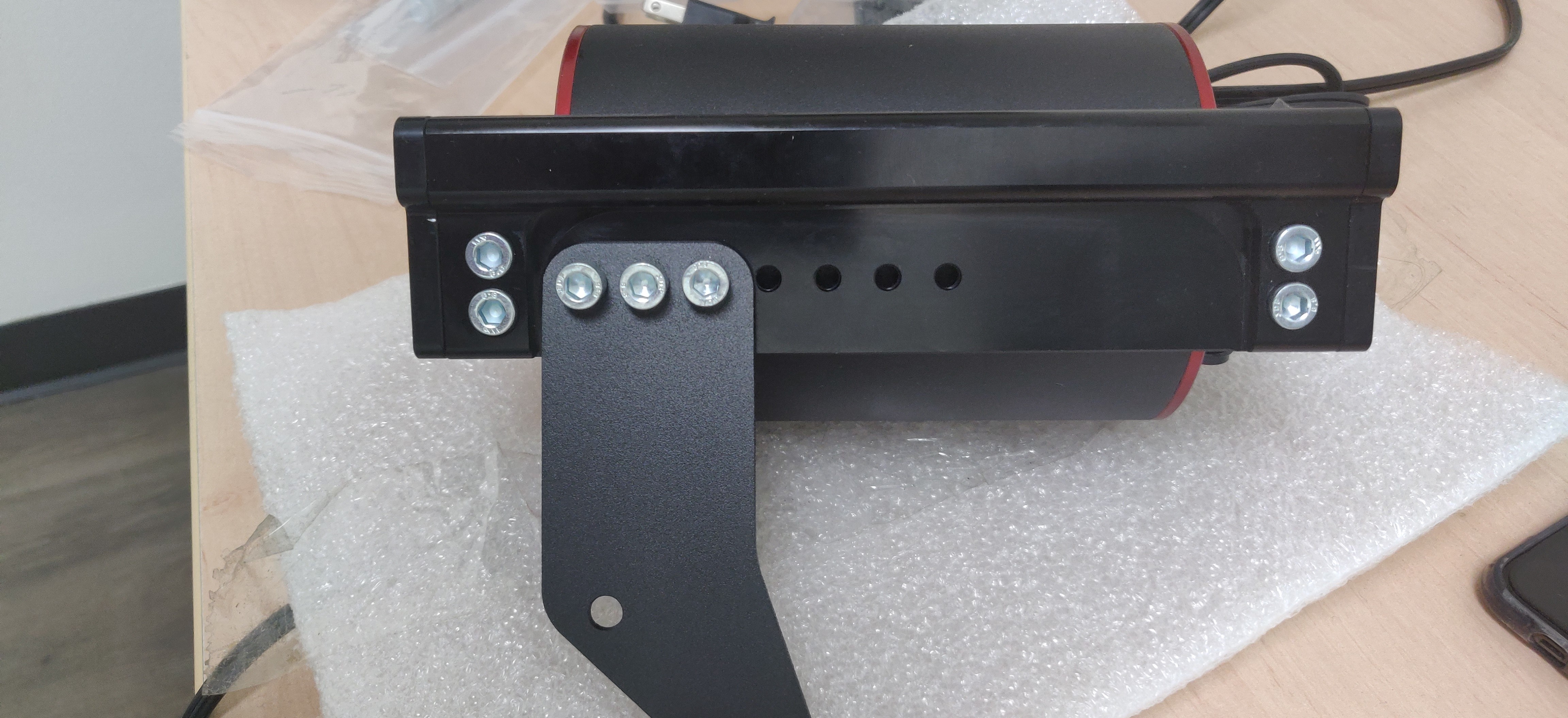
GR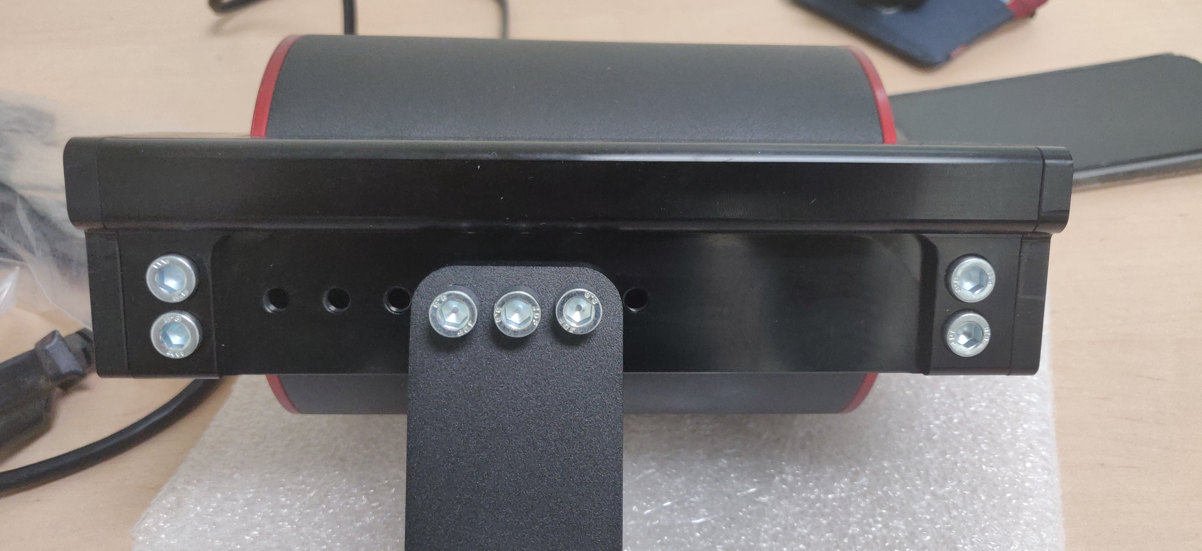
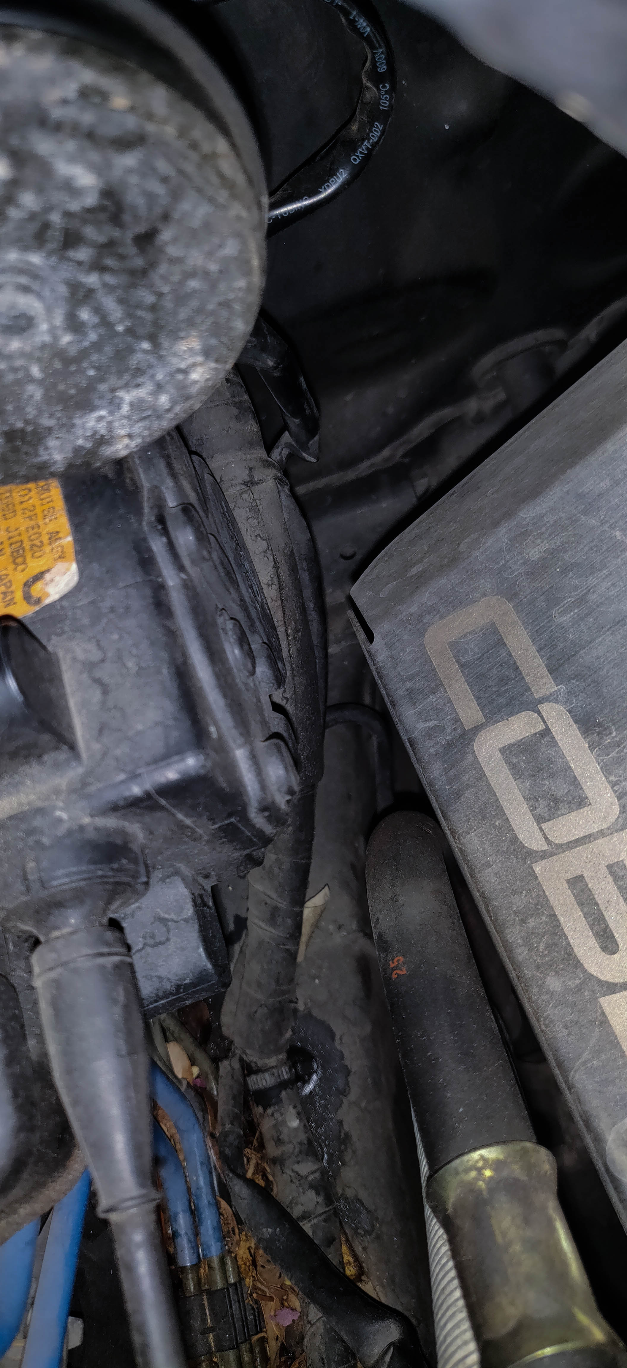
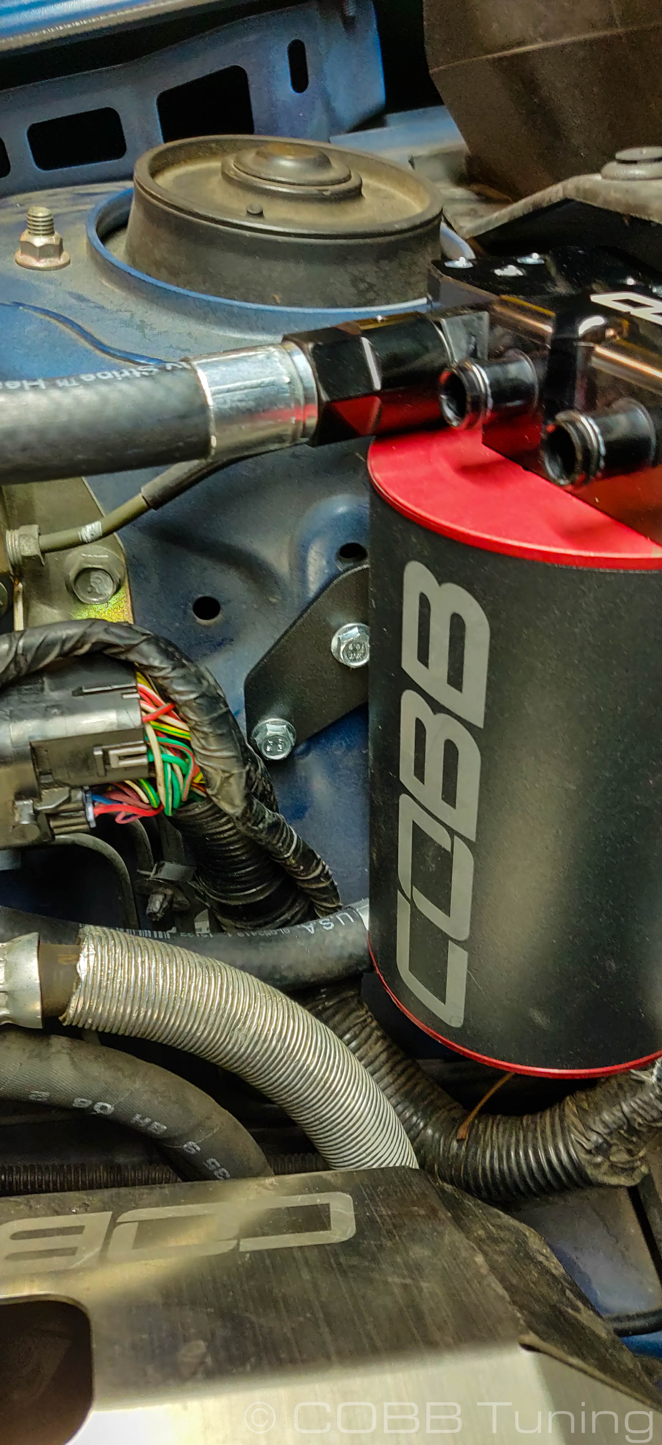
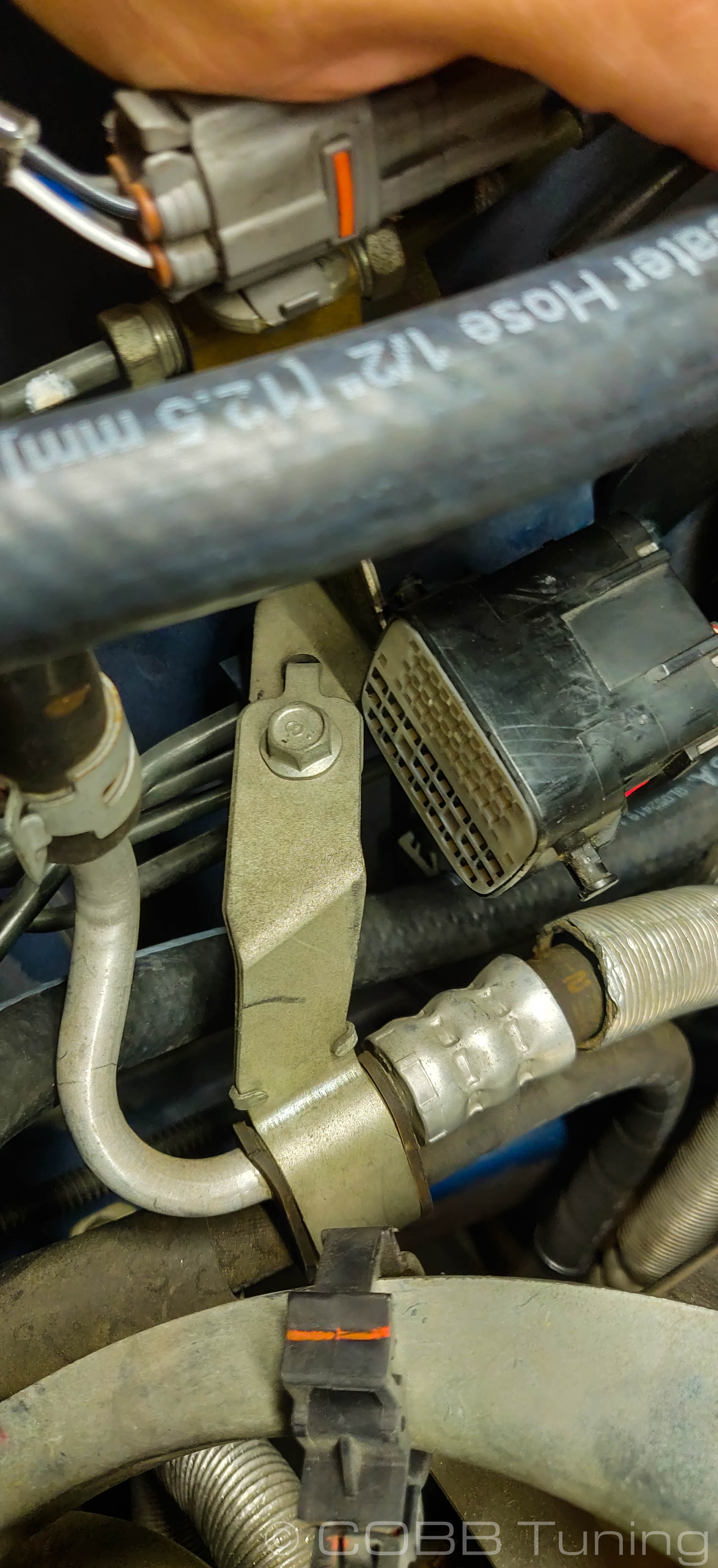
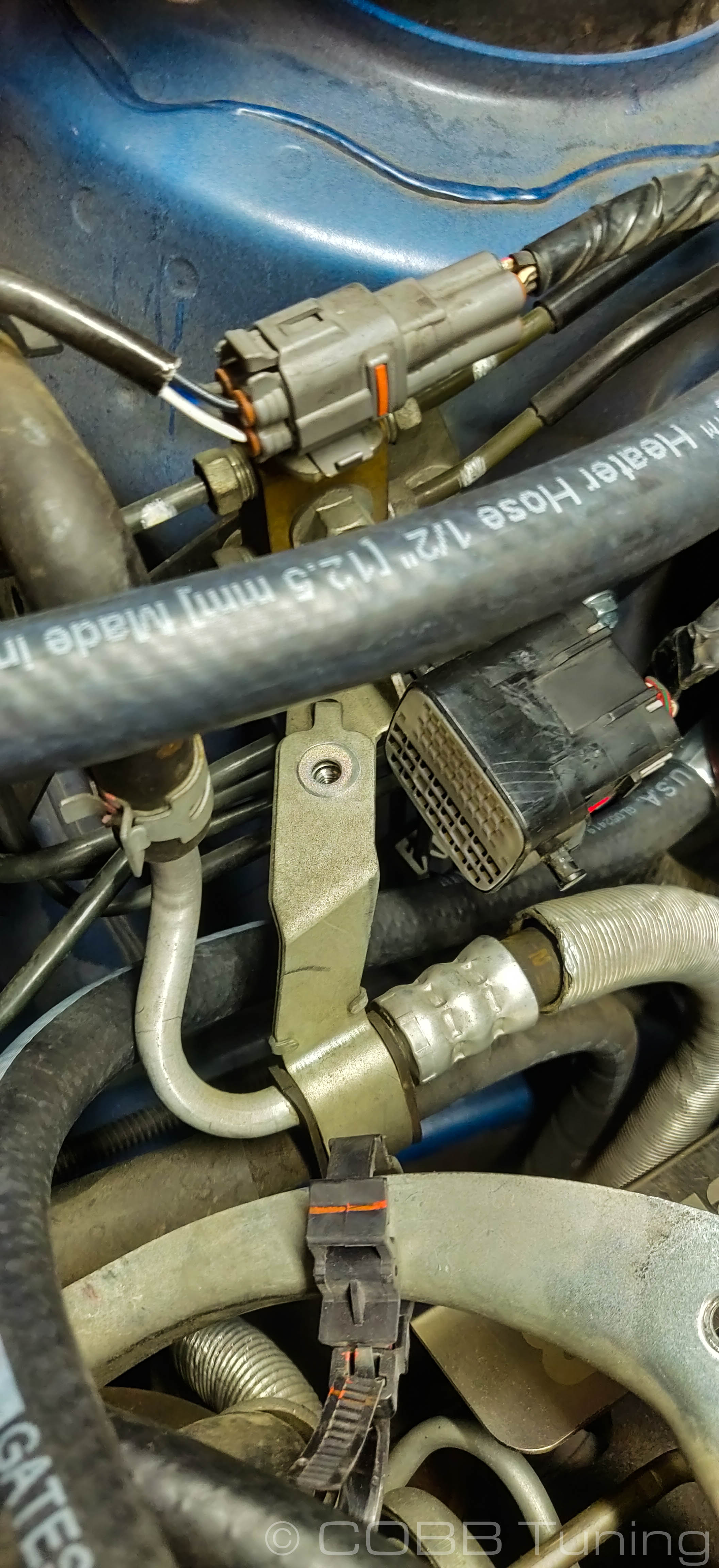
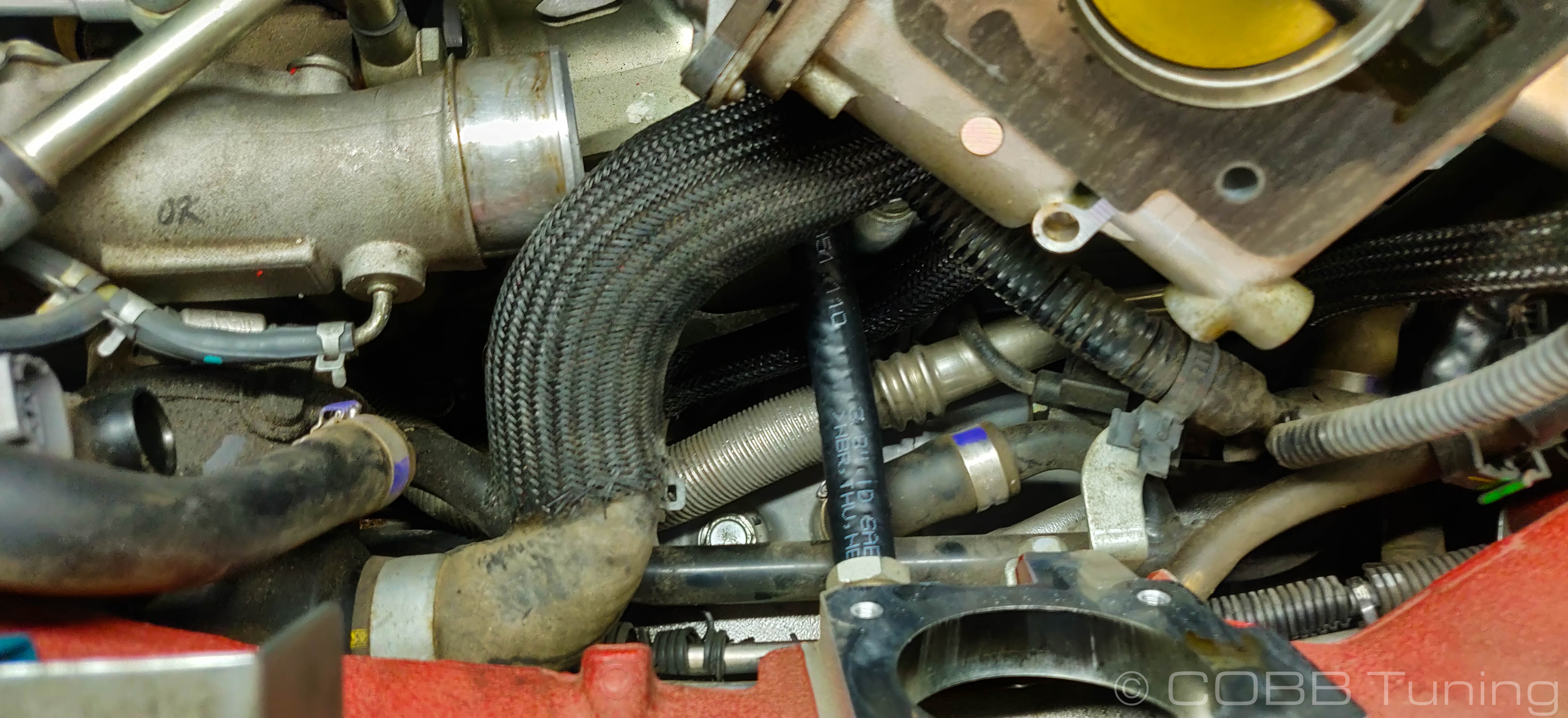
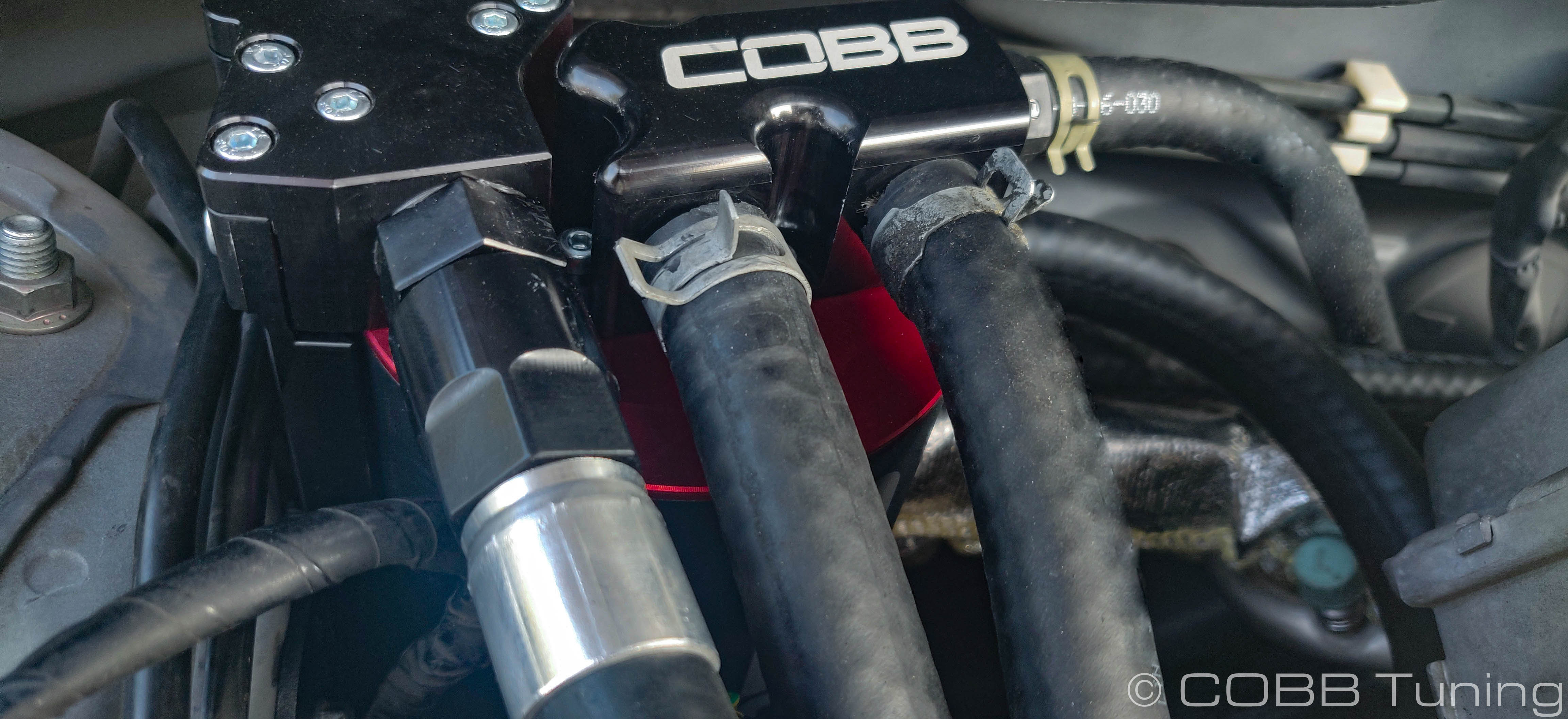
- Carefully navigate the AOS into place. you'll likely need to wiggle some things around like the harness and hoses to get them it in place. Bolt it down with the original or provided 10mm bolts. Loop the attached hoses out of the way for now. Tuck the lower coolant hose under the power steering bracket similar to the picture.
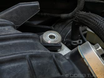
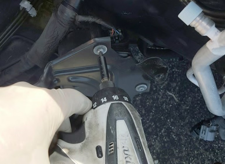
- Remove the bolt holding the power steering lines together using a 10mm socket.
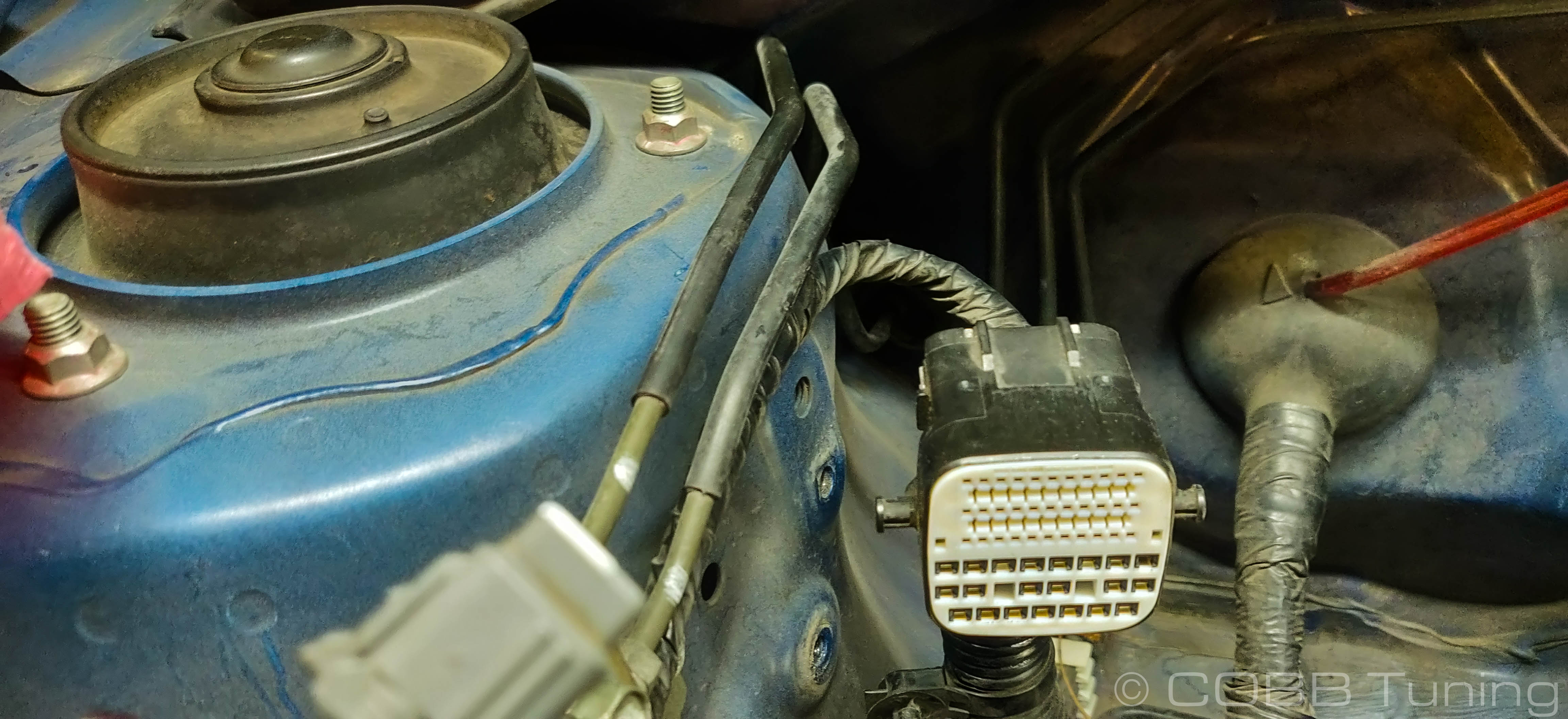
- Take the provided flat harness bracket and install it into the engine side of the harness connector. It can help if you lift the tab again, similarly to how it was removed from the original bracket.
- Bolt it down loosely using the original power steering bracket bolt, then connect it to the other half to find a good point where the harnesses aren't being strained before tightening it down.
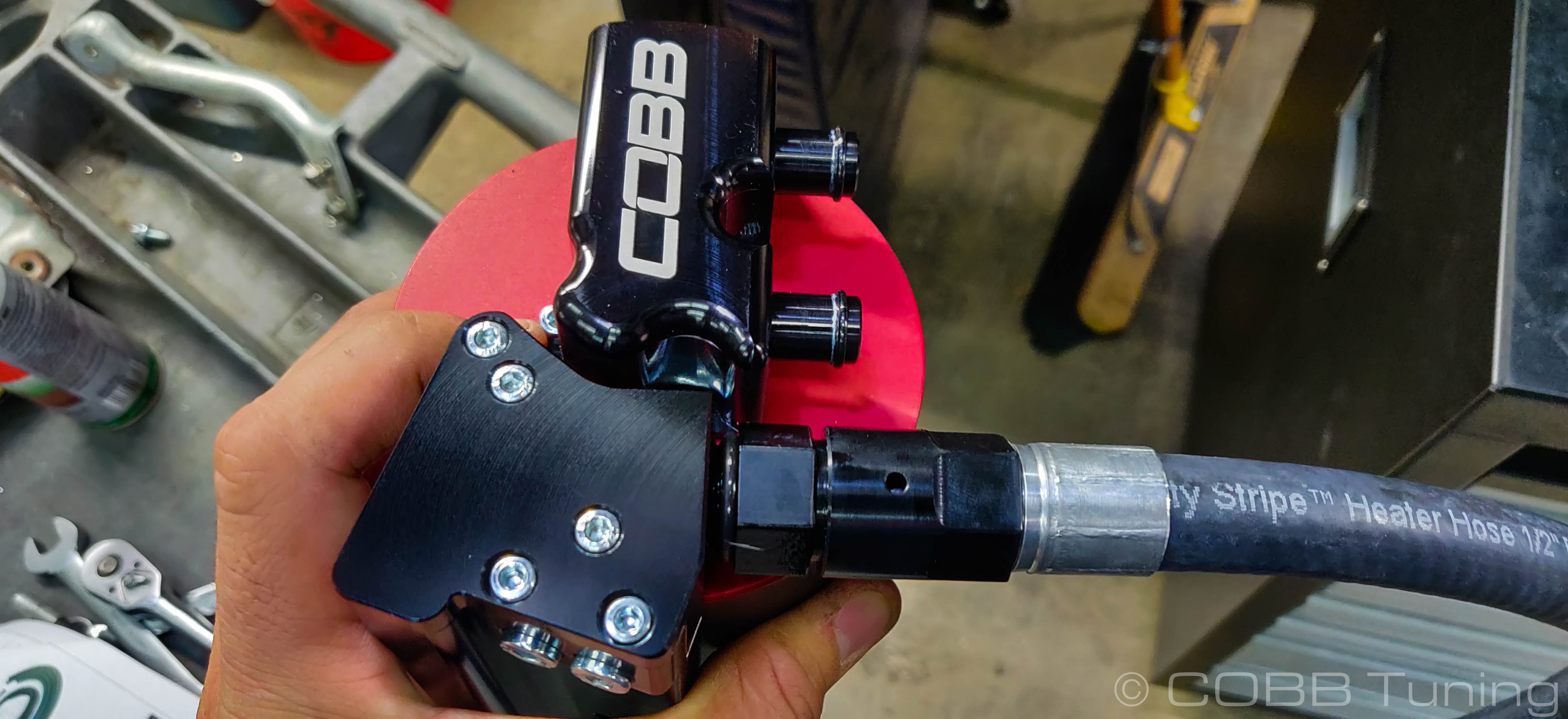
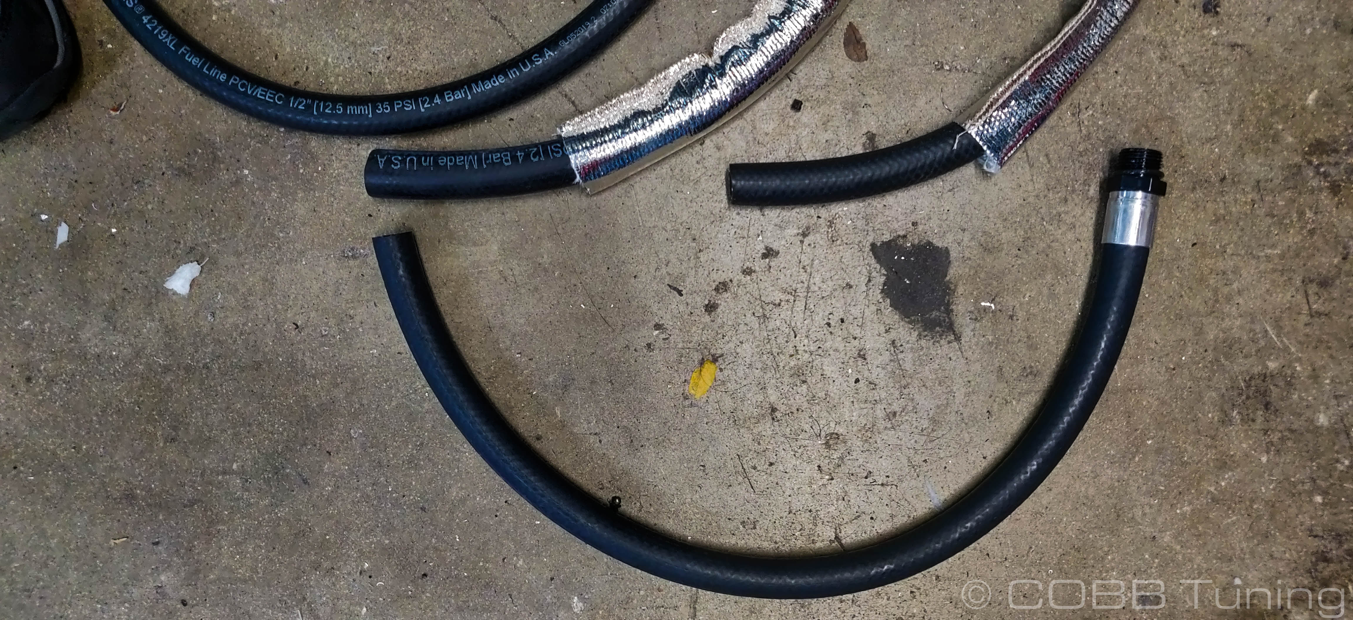
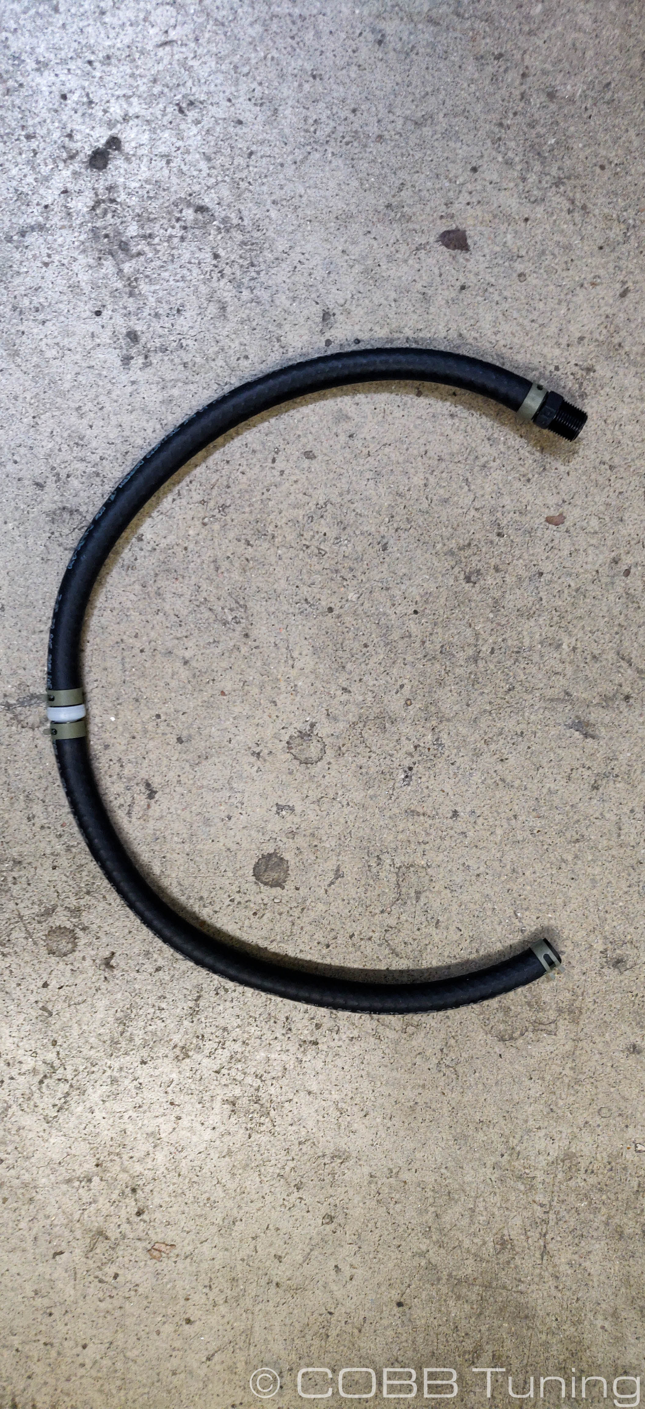
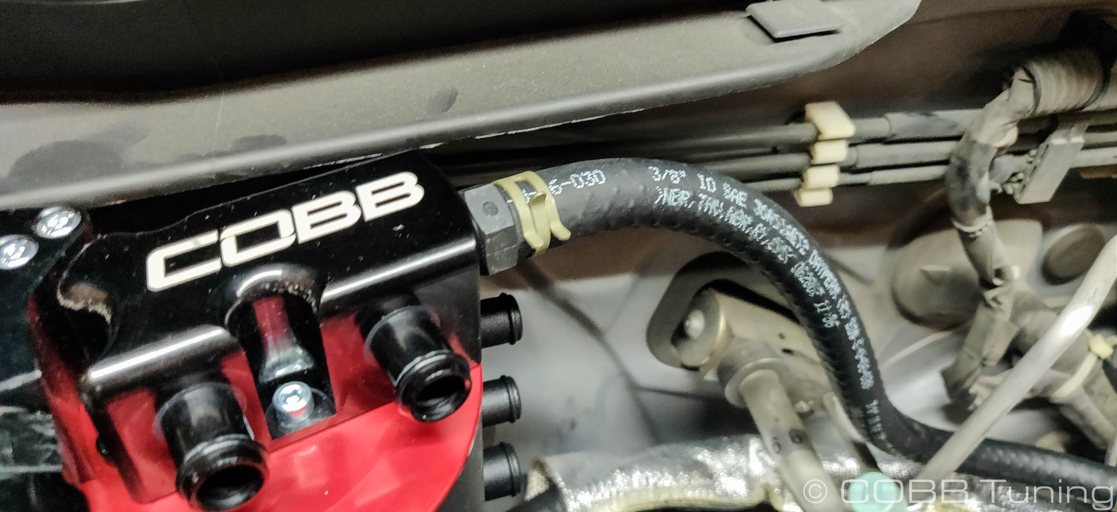
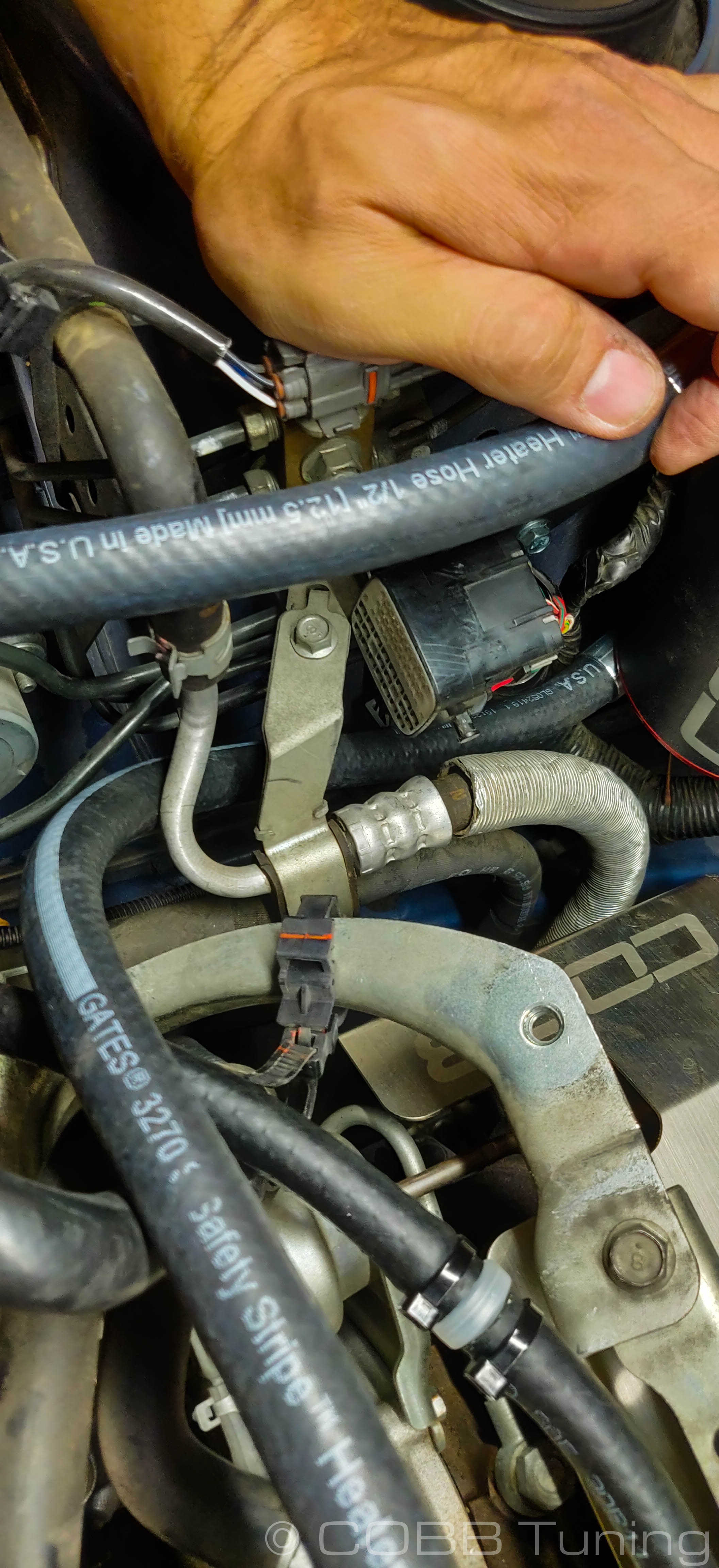
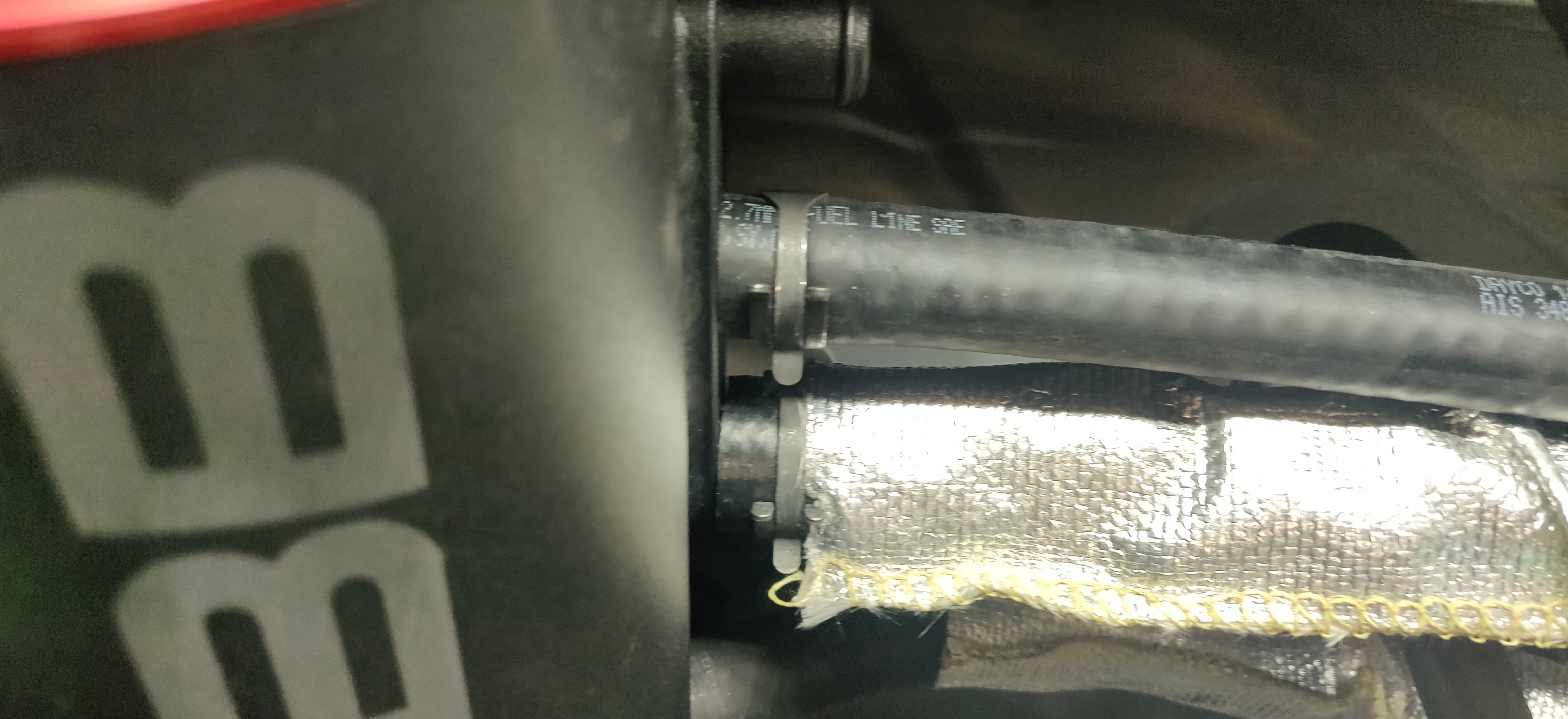
- Lastly we need somewhere for all the oil to drain back into the engine. Install the provided 1/2" line (with heatshield) onto the bottom port of the AOS using the pre-installed spring clamps on both ends. If you slide back the cover, the line should say 1/2" on it.
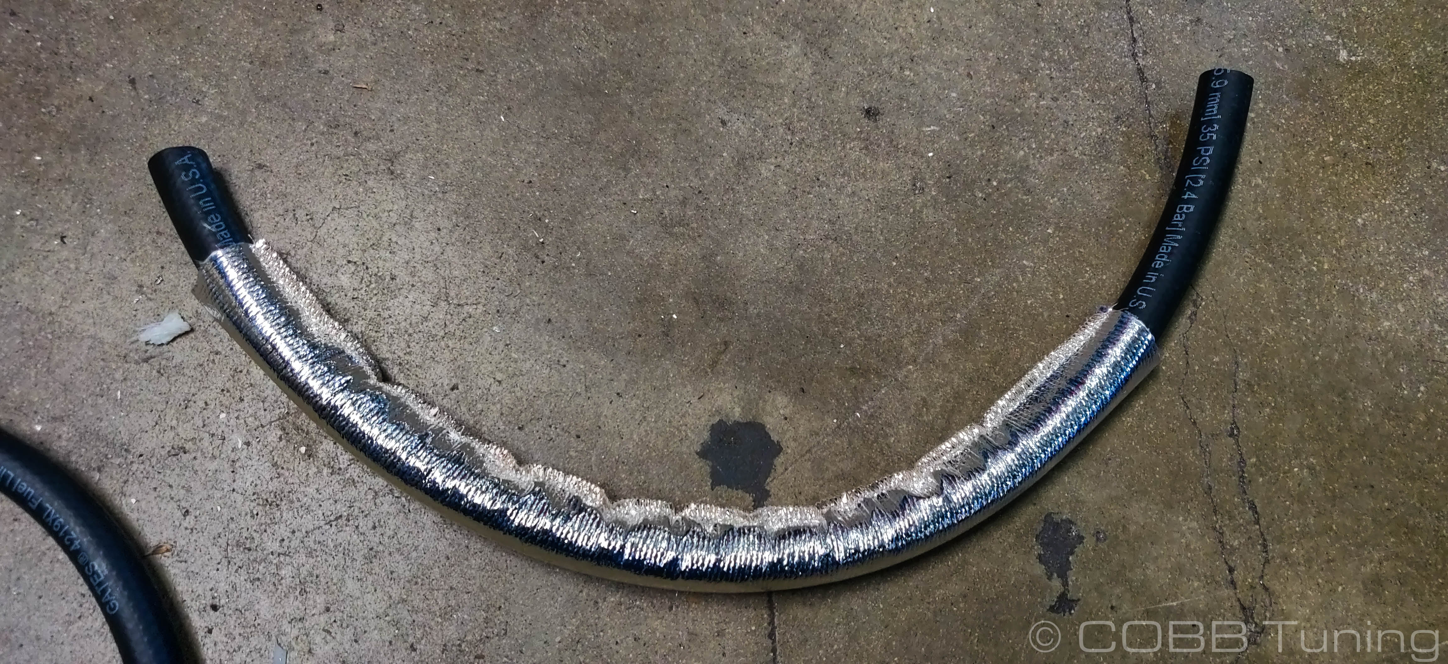
- After securing it with a spring clamp, run it into the smaller piece of the y-fitting installed onto the crankcase breather tube.
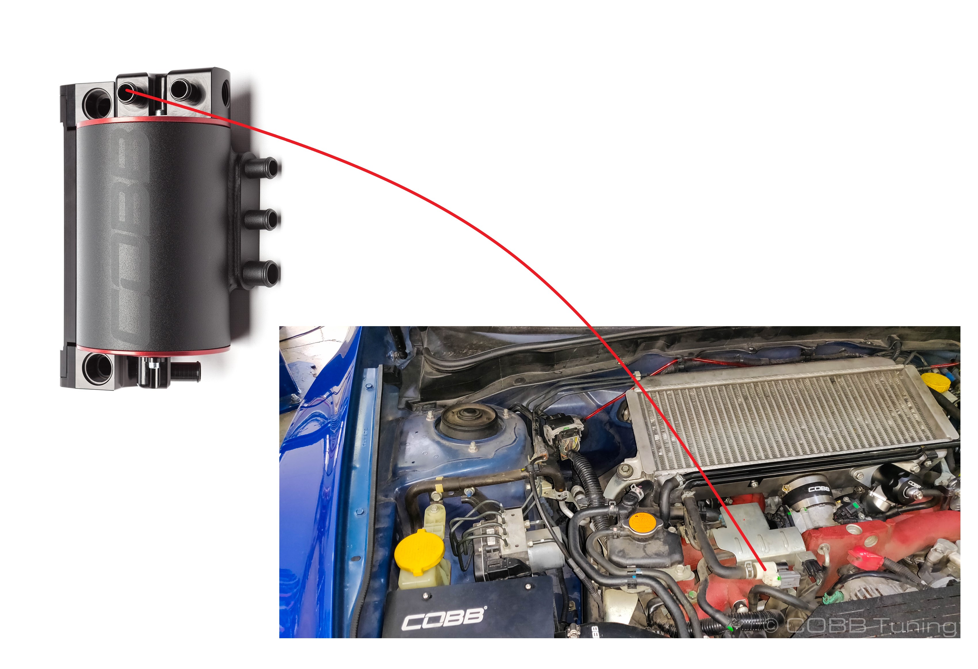
Reference Fig.
PCV Hose
Nex up we're working on replacing this section. With the one way valve in the line in both the original and COBB AOS, there is one side that is the "Vacuum" side going toward the intake side of the engine. While the other side is the Crankcase side of the engine, where oil vapor etc. is distributed to the turbo inlet and pcv valve.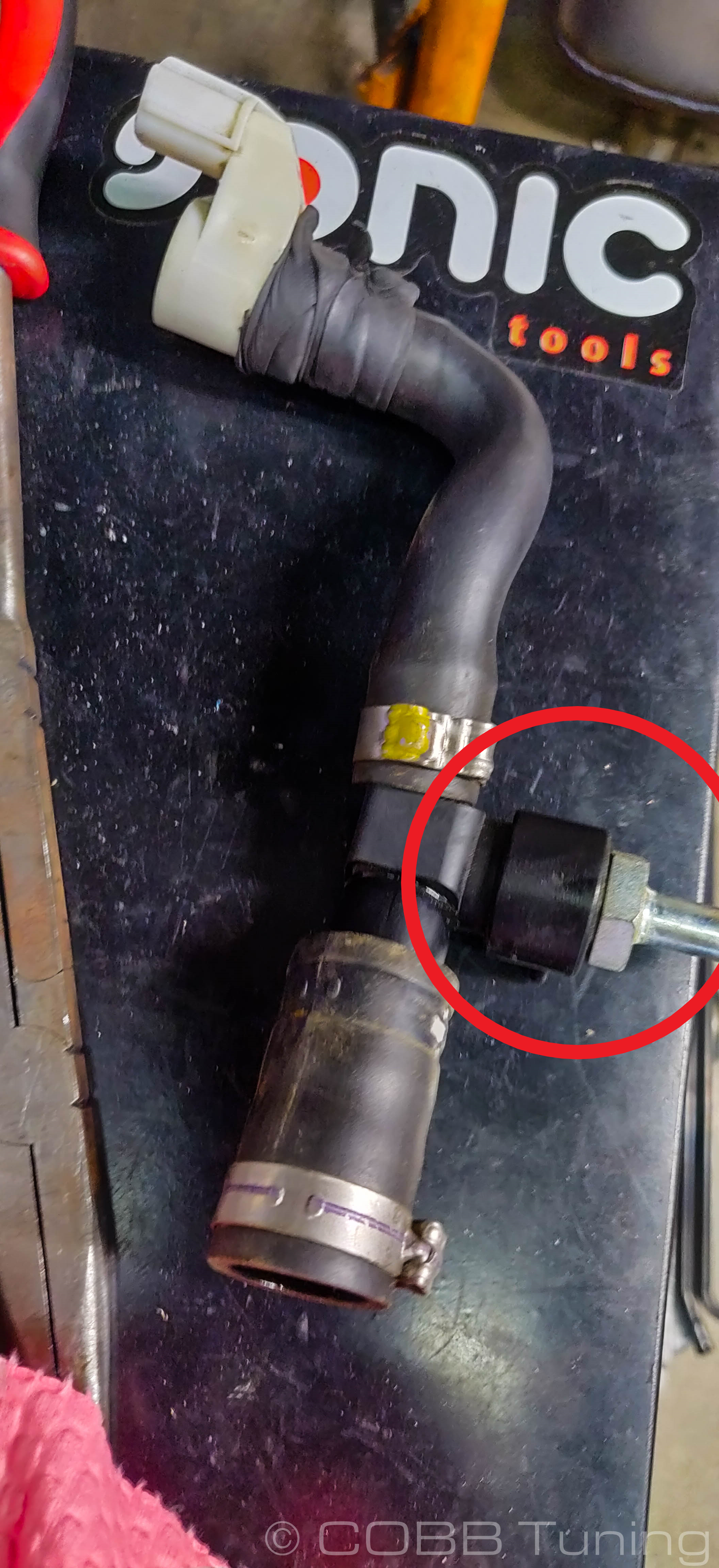
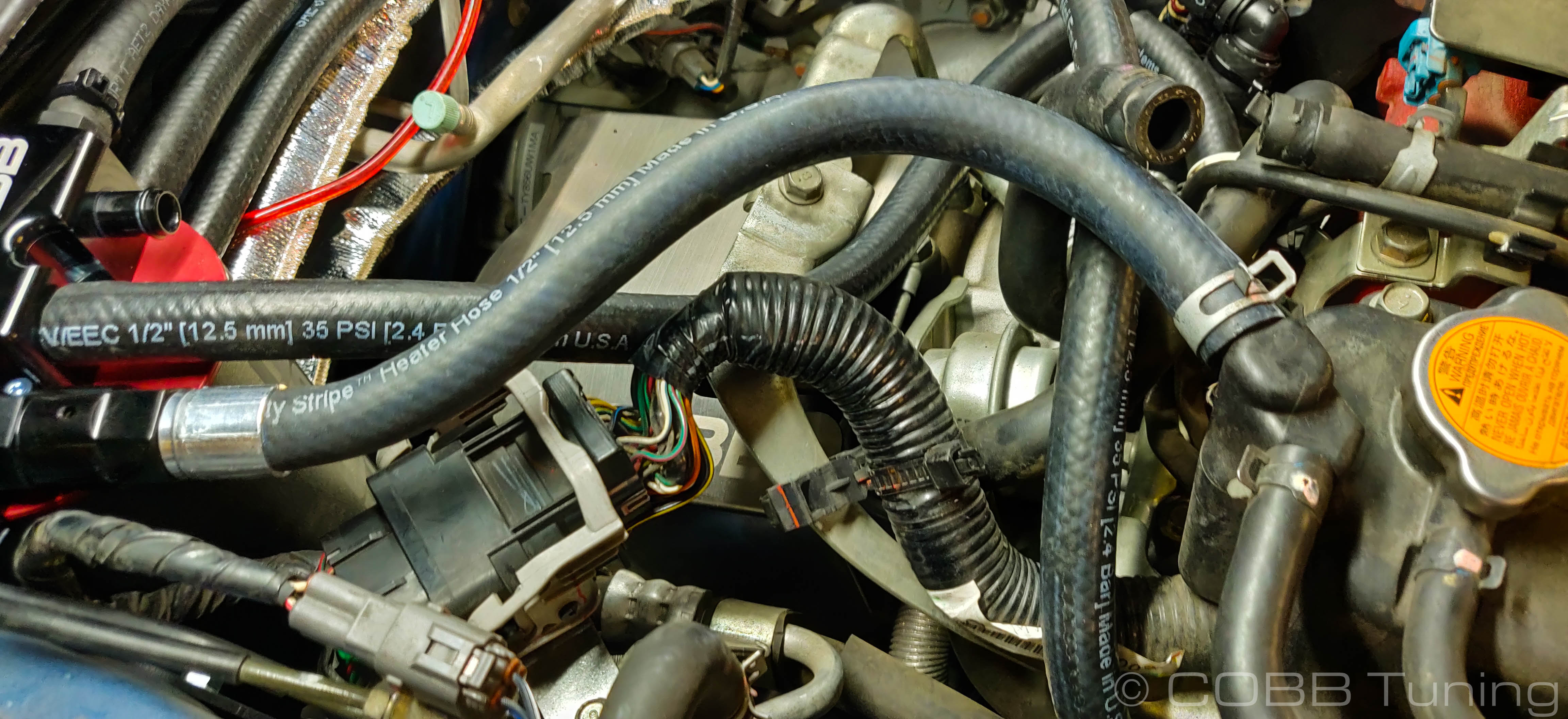
Vacuum Side (Engine Intake Side)
- We previously installed the PCV hose to the top threaded port on the PCV housing. This hose integrates a new pcv valve to make up for the one we removed. To get to where it needs to go can be a bit of a pain but is made much easier by removing the throttle body first using a 10mm socket to remove the 4 bolts holding it in place. Make sure to either have a replacement gasket on hand or not damage the gasket when removing it. You shouldn't need to unplug the MAP sensor or coolant lines, simply drape the throttle body slightly out of the way.
- At the bottom of the throttle body mounting plate you should see a metal fitting. Go ahead and pull this hose off and remove it from the car.
- Routing it away from anything hot, hook the PCV hose up to this fitting and use the spring clamp both to reduce the possibility of leaks.
- It should now run from the top port of the AOS to just under the throttle body. Secure the line with the factory spring clamp.
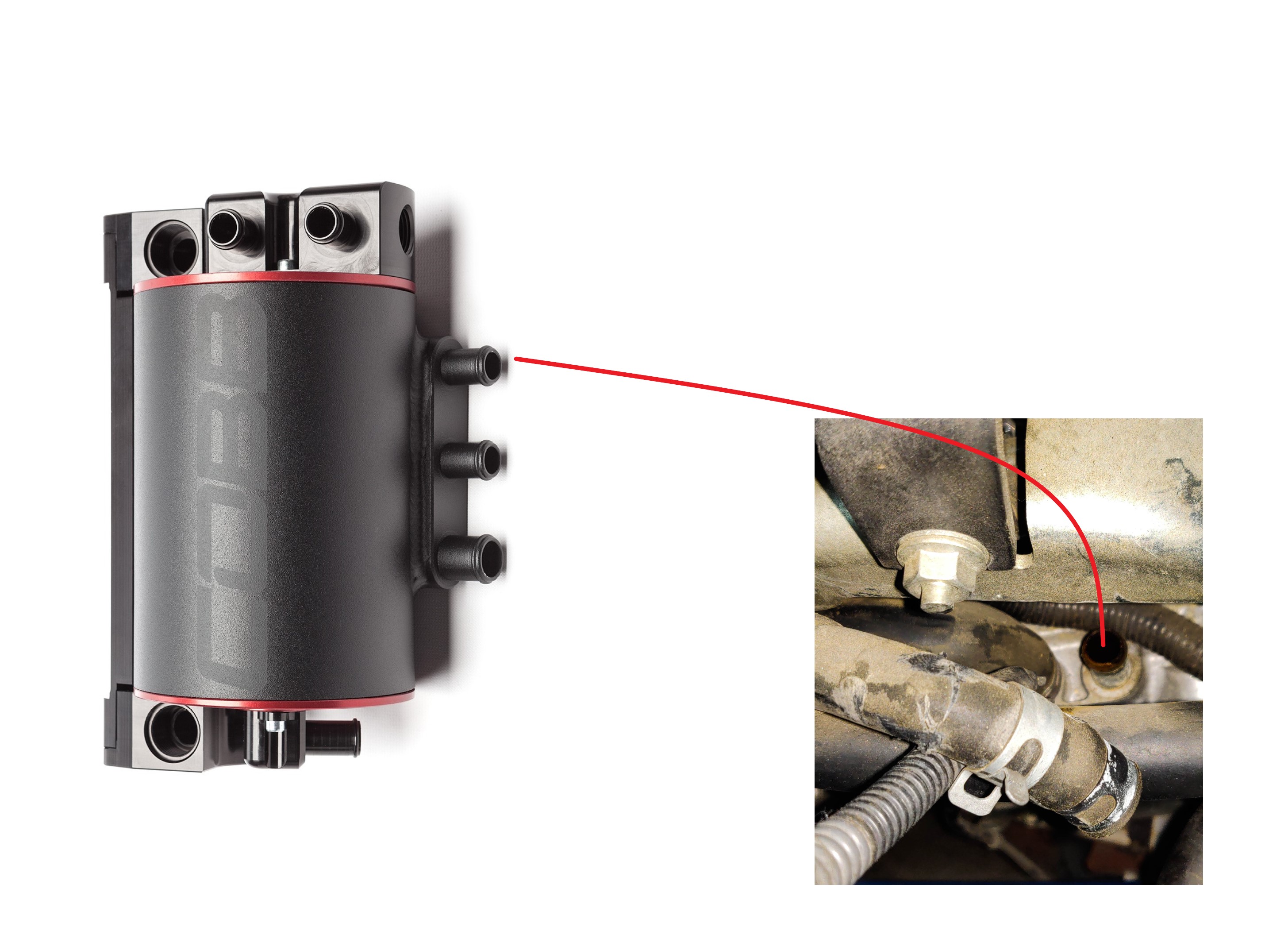
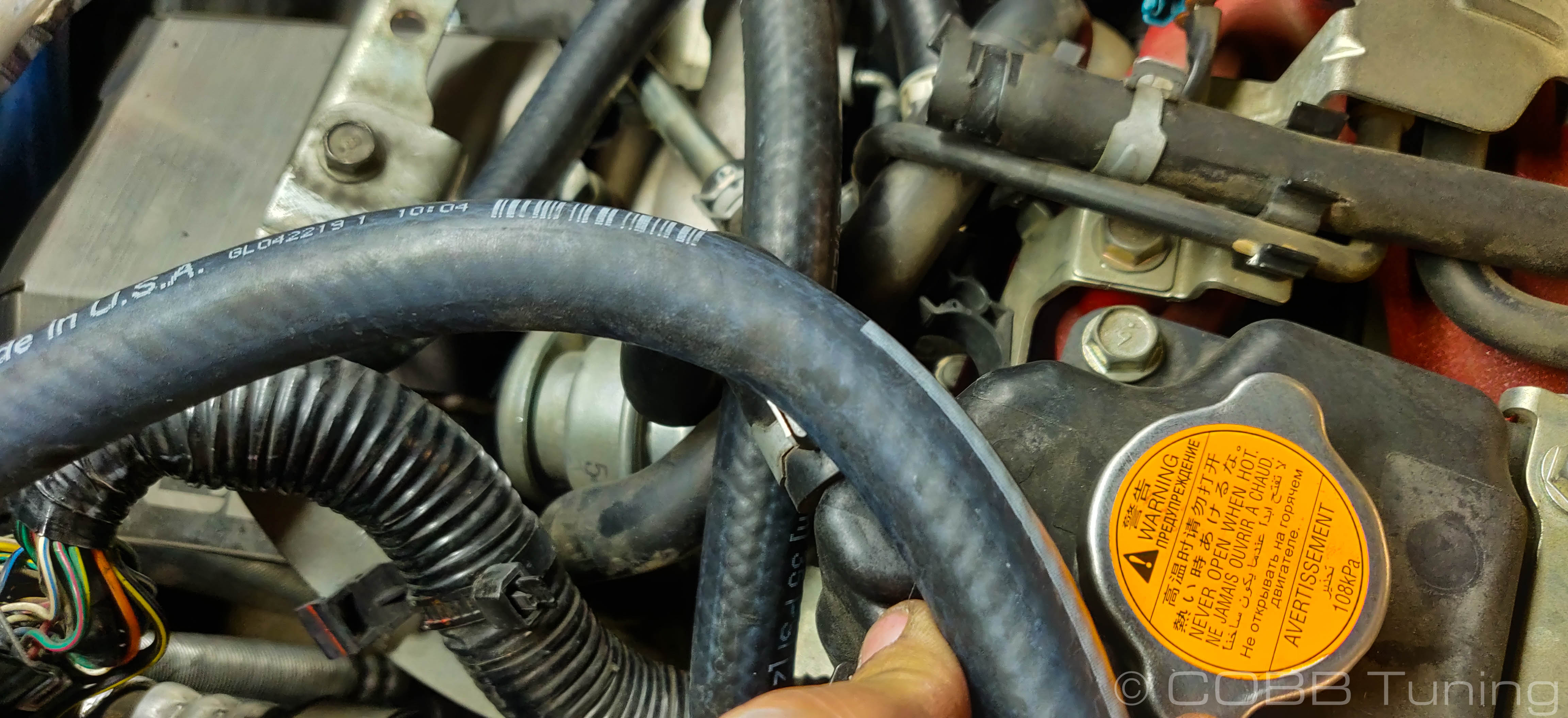
Pressure side (Crankcase)
- This side of the PCV valve is where engine crankcase pressure or oil vapor go up to the PCV valve. You'll run a 5/8" hose (with heatshield) around to the larger top fitting of your oil drain y that was installed. In some cases it can be easier to cut a small piece of hose off, then use a 90 degree fitting to adapt it on to make turning the hose a little easier. Make sure to secure all of your connections with the provided spring clamps. In some instances you can use the stock spring clamps as well.
- You'll route this away from heatsources to the larger bottom fitting of the AOS.
Reference Fig.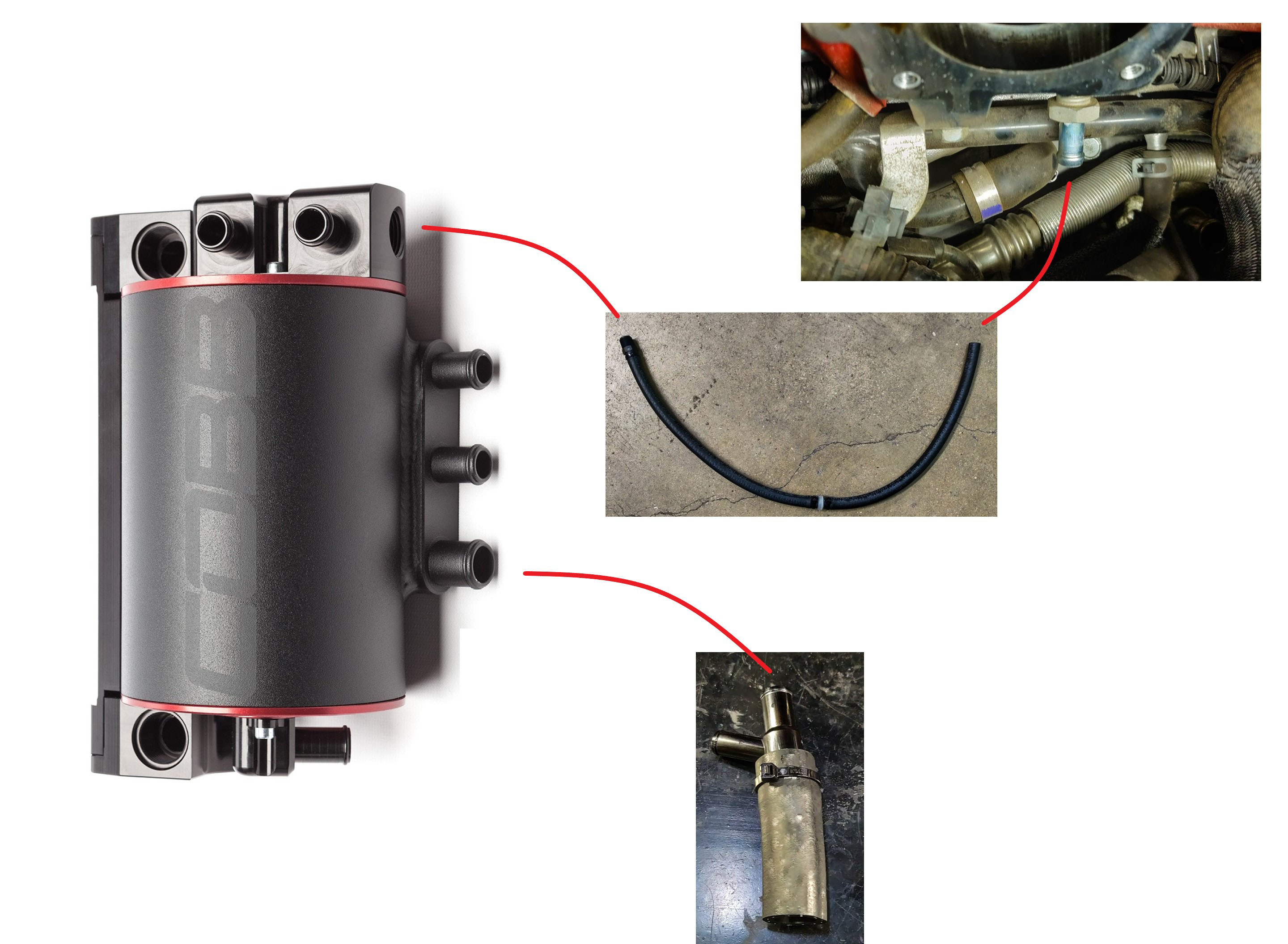
Left Side Valve Cover Breather (From Driver's Point of View)
Left Side 02-14
- On the left side of the cylinder head under the injector rail cover and near the battery, you should see two hoses going into the valve cover. One has a crimped hose clamp and one uses a spring clamp. Go ahead and remove the spring clamp and pop this hose free. (bent needlenose pliers can help a lot here)
- You should be able to wiggle that hose out, the other end was previously attached to the metal breather tubes going along the front of the intercooler.
- Grab some of the bulk 1/2" hose and attach one end to the valve cover using a factory spring clamp. It is another situation where using a small trimmed bit and a 90 degree fitting can make things easier. Route the hose away from any abrasion and heat sources towards the AOS. Secure the lower piece on using the spring clamps from the stock line. If you use a 90 degree adapter make sure to secure all junctions using the provided spring clamps.
- Attach the hose to the middle fitting of the AOS.
Reference Figure. (02-14)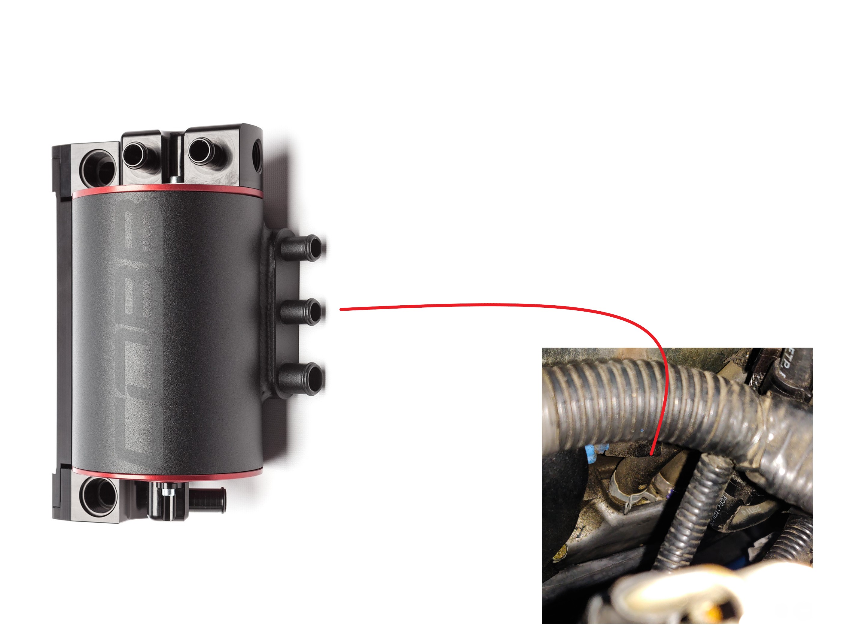
Left Side 15-19
- On the left side locate the white crankcase breather fitting where it attaches to the PCV Crossover Tube. You'll need to remove the tube from the crankcase breather. To do so, hold the wiring harness tab and pull the white fitting outward.
- Using the provided black fitting, insert this into the white crankcase fitting and rotate it so the hose points towards the AOS.
- Using your 1/2" breather hose, route a section to the middle port on the side of the AOS. Secure your hoses with spring clamps.
Reference Fig. 2018 - 2019
Right Side Valve Cover Breather (From Driver's Point of View)
Right Side (02-14)
- On the right hand side cylinder head forward of the wiring harness we dealt with earlier, you should see two hoses going onto the valve cover underneath the injector cover. One of them has a crimped hose clamp and one uses a spring clamp. Go ahead and remove the spring clamp and pop this hose free. (bent needlenose pliers can help a lot here)
- You should be able to wiggle that hose out, the other end was previously attached to the metal breather tubes going along the front of the intercooler.
- Grab some of the bulk 1/2" hose and attach one end to the valve cover using a factory spring clamp. It is another situation where using a small trimmed bit and a 90 degree fitting can make things easier. Use the spring clamps off the oem line to secure your connections to the valve cover and 90 degree adapter. Then use the supplied ones in the kit around the connections going from the connector to the AOS itself.
Reference Fig.
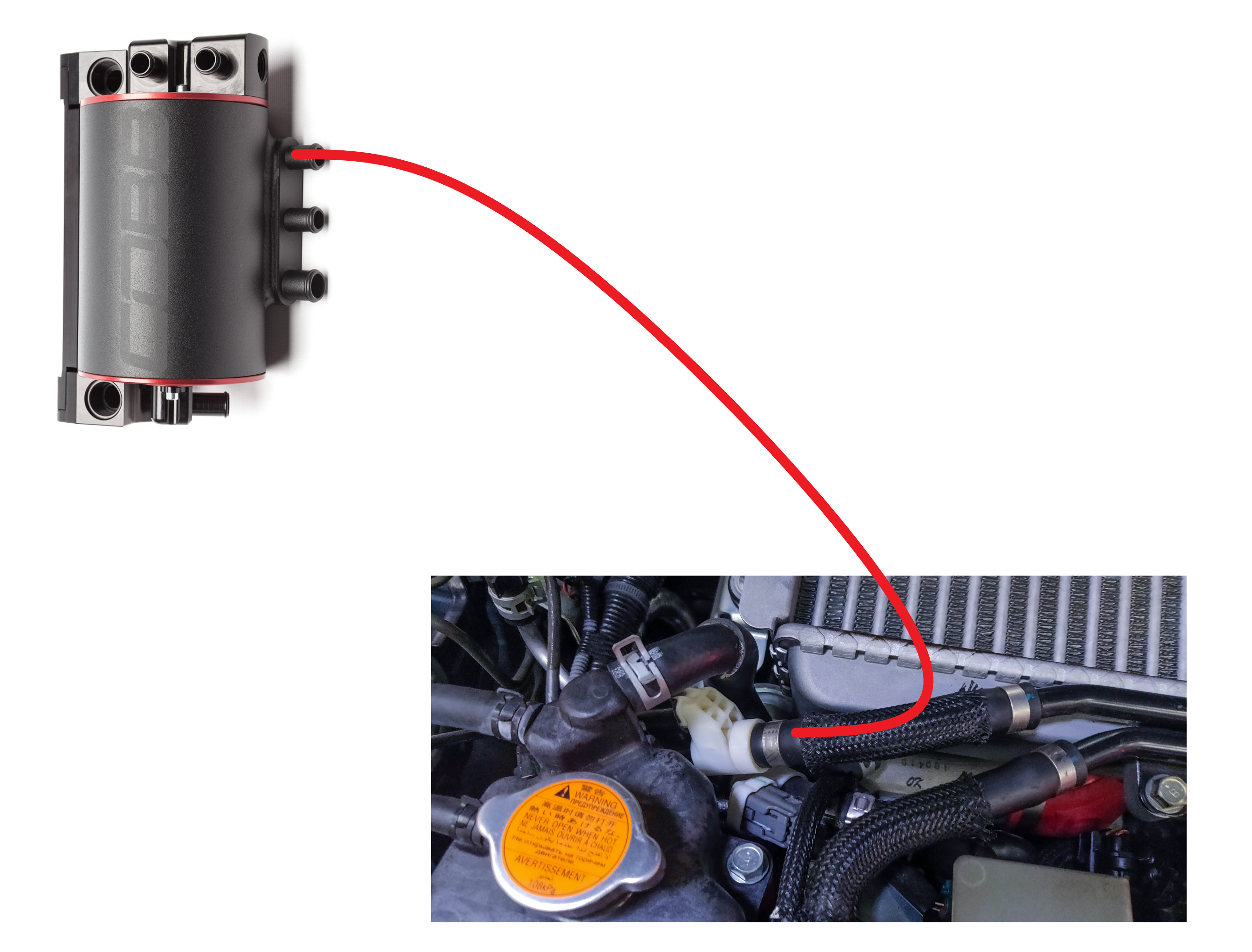
Right Side (15-19)
- On the right hand side cylinder head (From driver's perspective) you should see 2 hoses coming out, one of which is going up to this fitting that attaches to the crosssover tube.
- Using a flat blade screwdriver pry apart the crimped section of the clamp holding it to the white blowby sensor and remove the crossover tube from the car.
- Attach your 1/2" hose to the white blow-by sensor wth a spring clamp and run the line to the top port on the side of the AOS securing that with a provided spring clamp as well.
Reference Fig
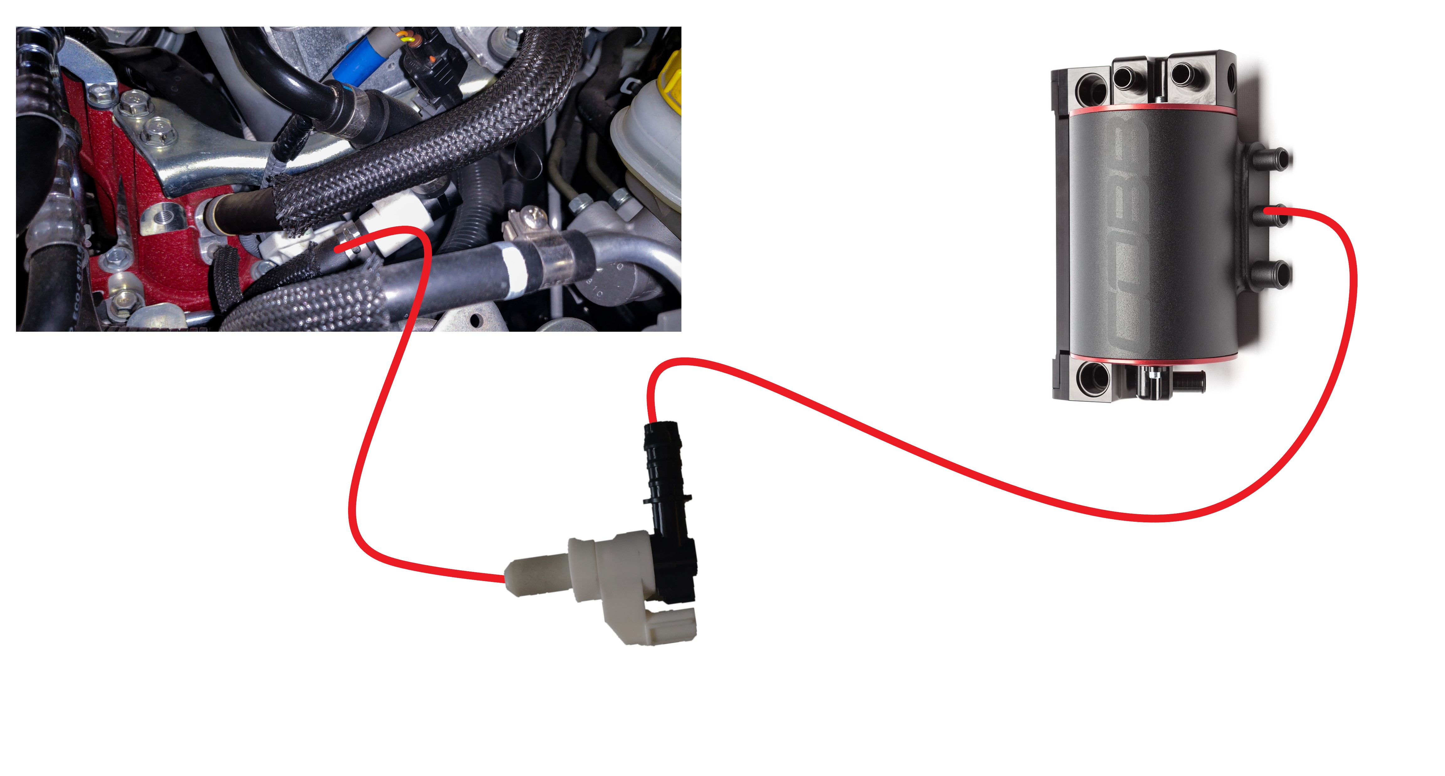
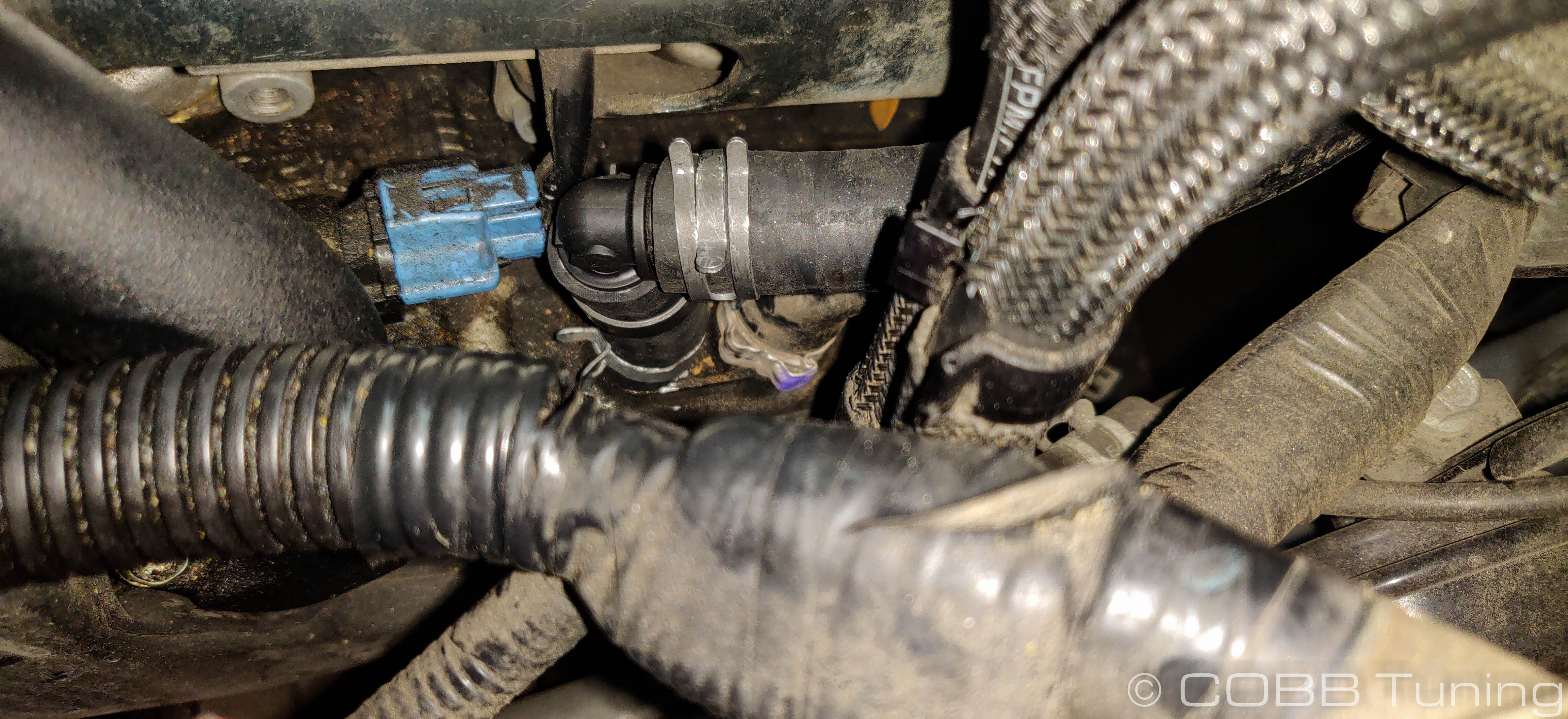
Crankcase Blow-By Sensor Rear (Turbo Inlet) Fitting
This sensor formerly measured the air between the crankcase breather fitting and the turbo inlet. Given that this funcitonality is a good thing, we'd like to retain it.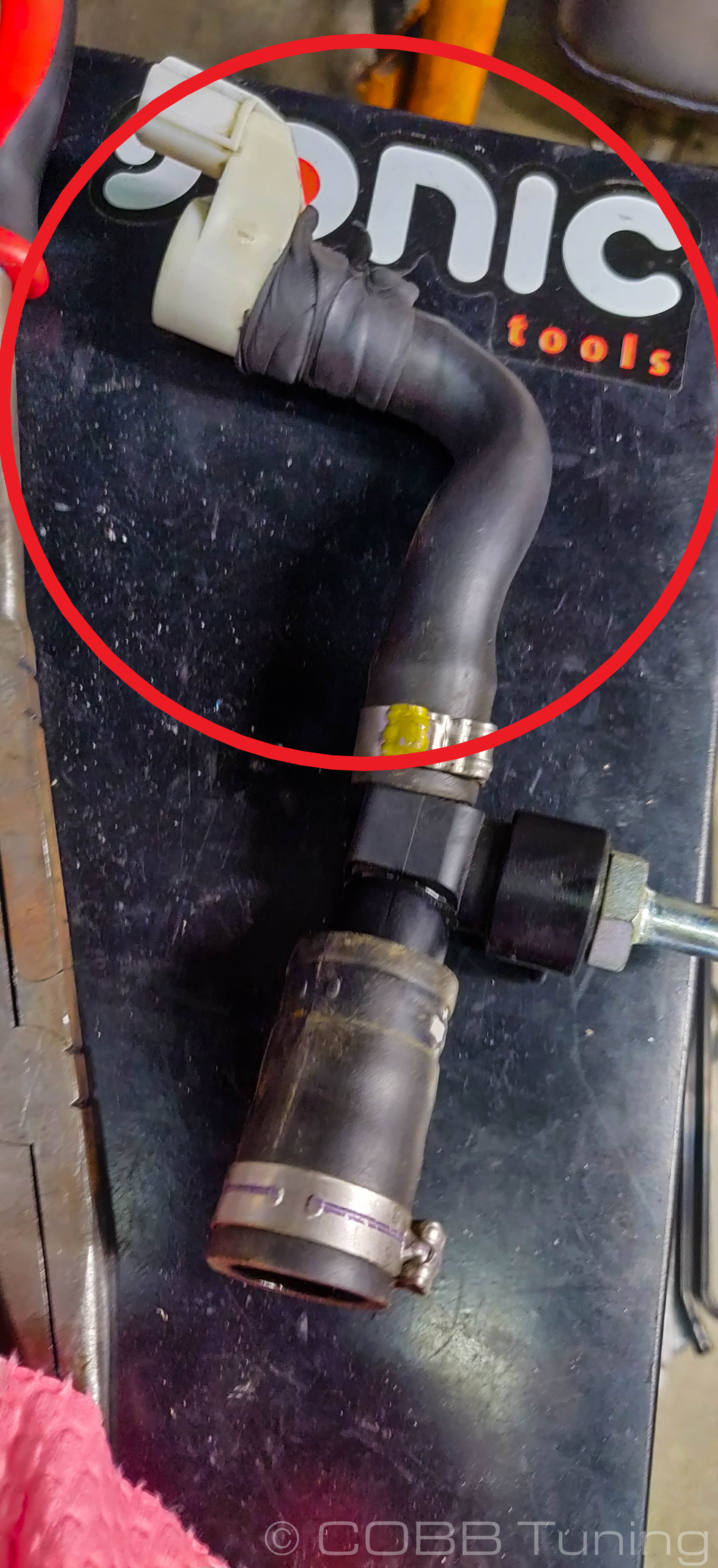
- Start by removing the sensor from the hose. In our case it involved unwrapping the tape sealing a minor leak, as well as carefully uncrimping the metal clamp by twisting a flatblade screwdriver.
- Go ahead and pop the sensor back in to the turbo inlet.
- Attach a piece of the 5/8" PCV hose to the sensor. Secure it with a supplied spring clamp. (Don't crimp it as depicted, we were in the middle of adjusting some other things around)
- Route it away from any heat sources to the right side port on the top of the AOS.
Reference Figure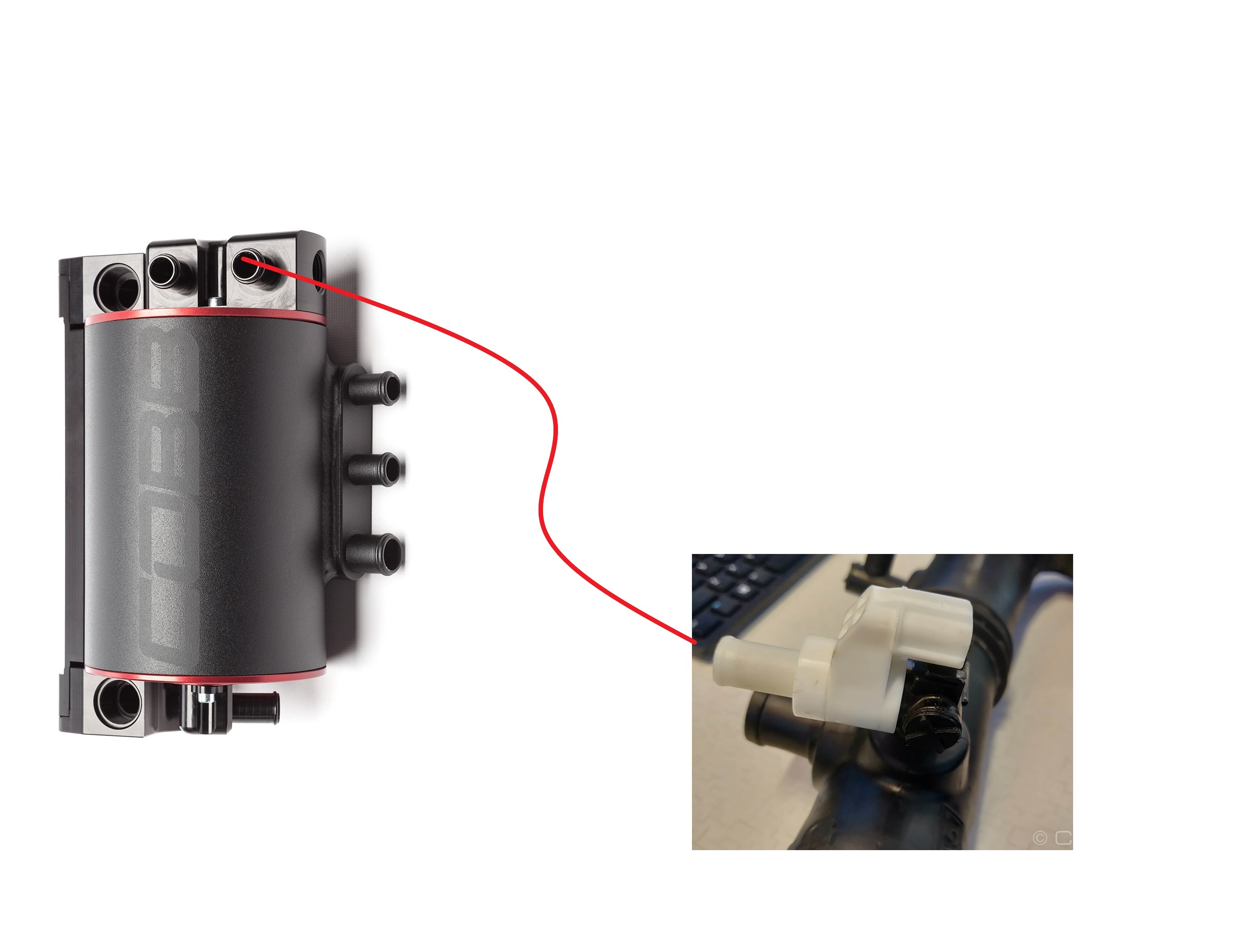
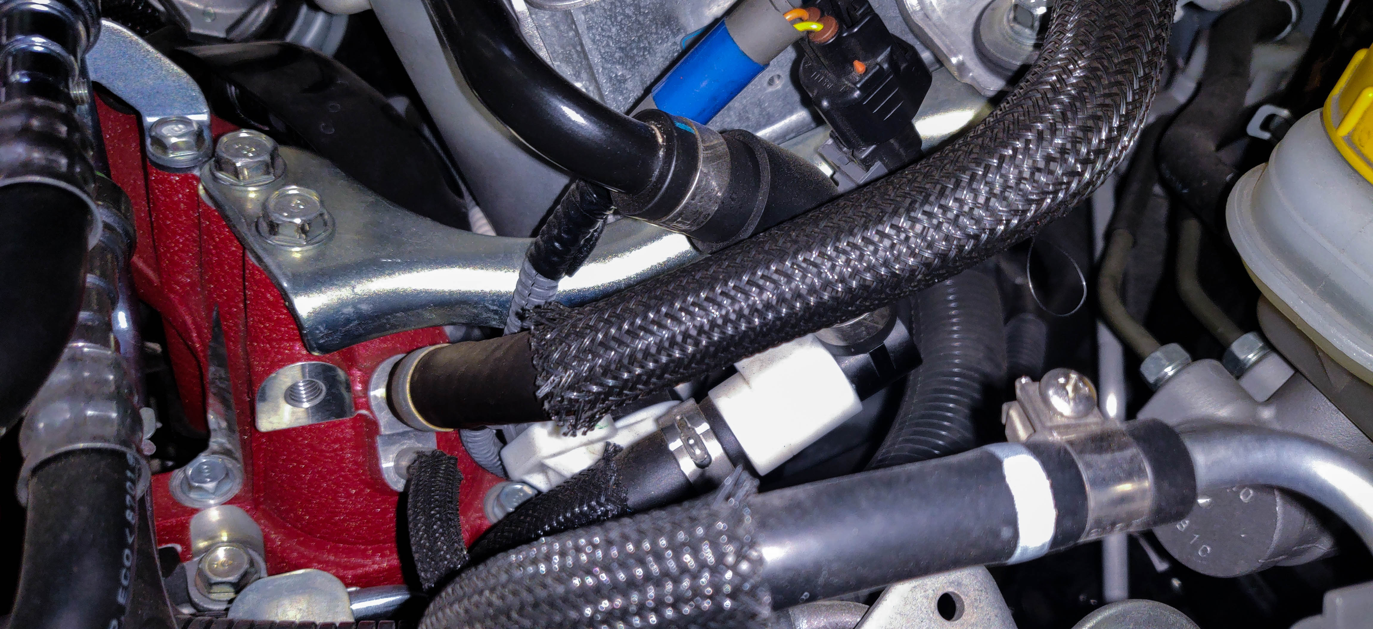
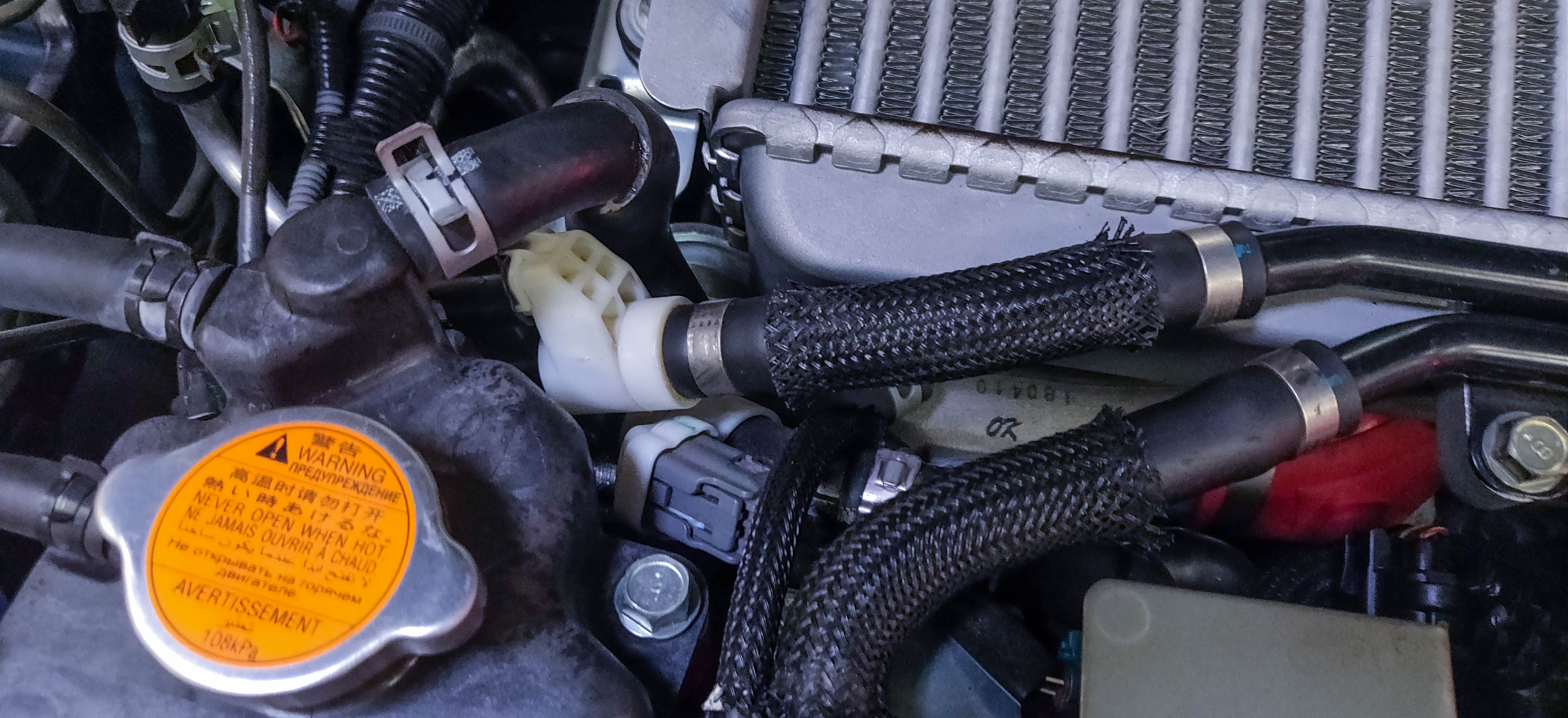
Crankcase Blow-By Sensor Front
This line can be re-installed after the TMIC installation which can make things easier as there are already a lot of hoses in the way.
- The next line you'll install attaches to where the last metal breather tube attached going towards the front of the car.
- Spring clamp the hose onto the sensor using the factory spring clamps. Some model years will not have this sensor here, in that instance you can go straight to the inlet itself. In either event route the line away from any heat sources.
- Lastly install the other end to the top left fitting between the other Crankcase hose and the upper cooling hose.
Reference Fig.
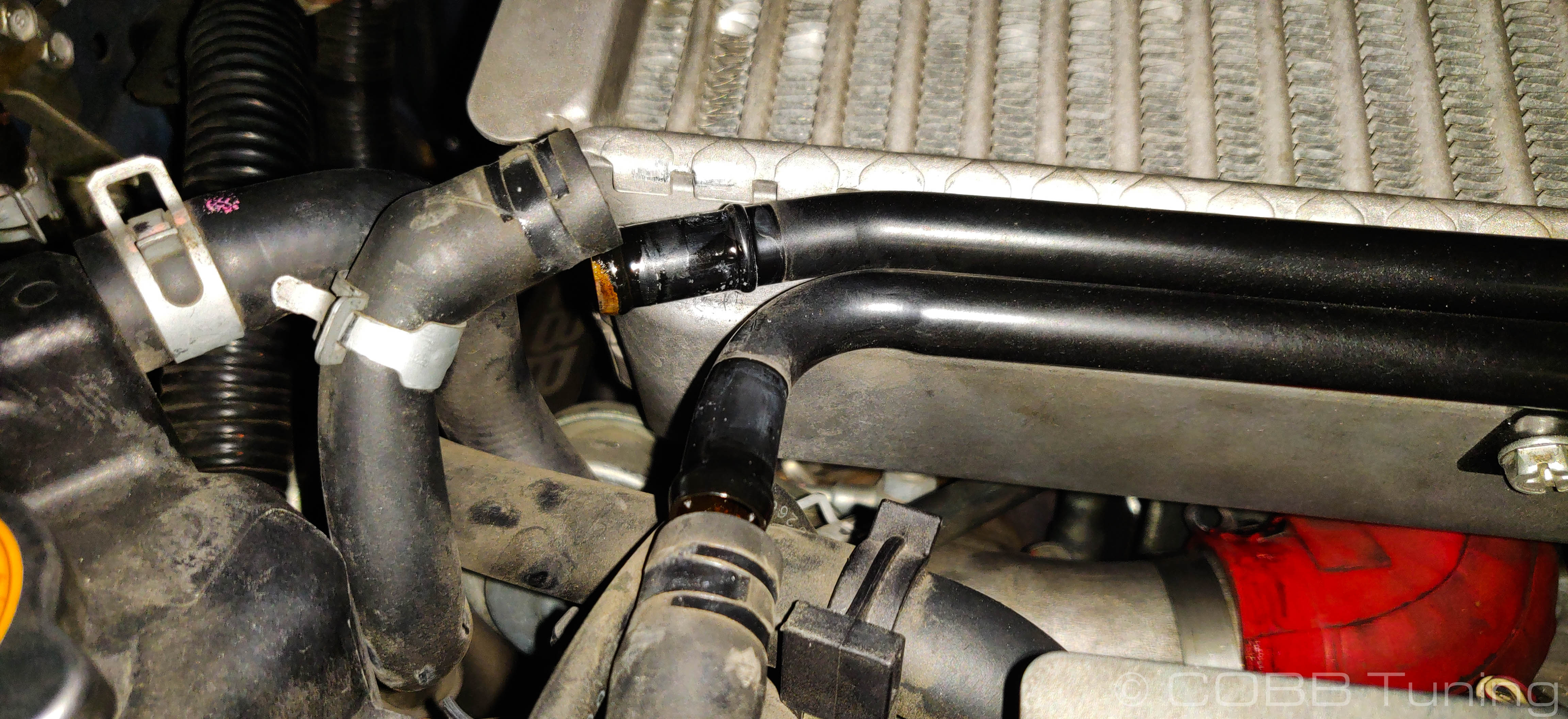
Lower Cooling Hose
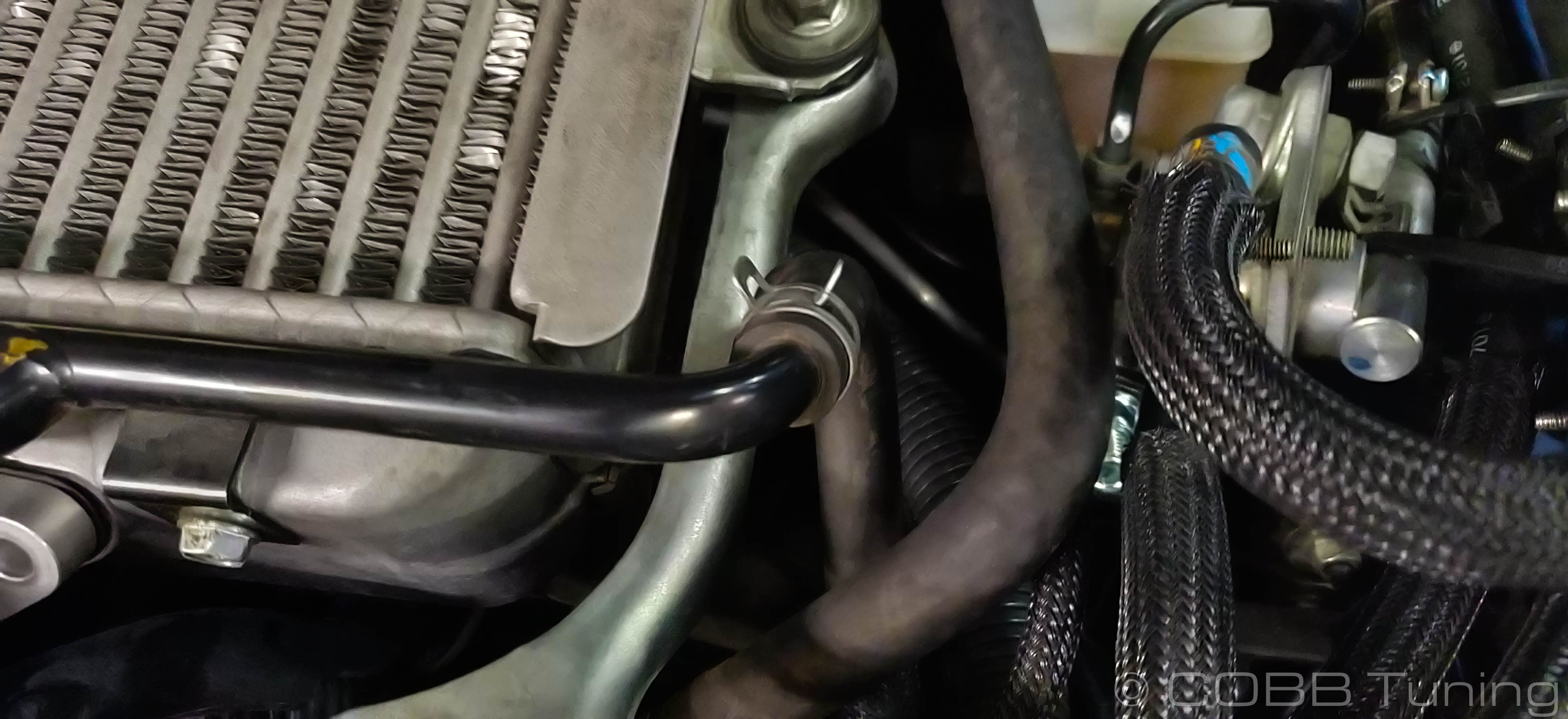
- Find the space where the coolant expansion tank hose goes down to the turbo. We're going to go inline with this hose in order to add coolant to the AOS. This added warmth helps burn off moisture and turn most burnables into a gas in order for them to burn without leaving a residue in the intake. At the same time the oil will condense and go down the drain line back into the engine.
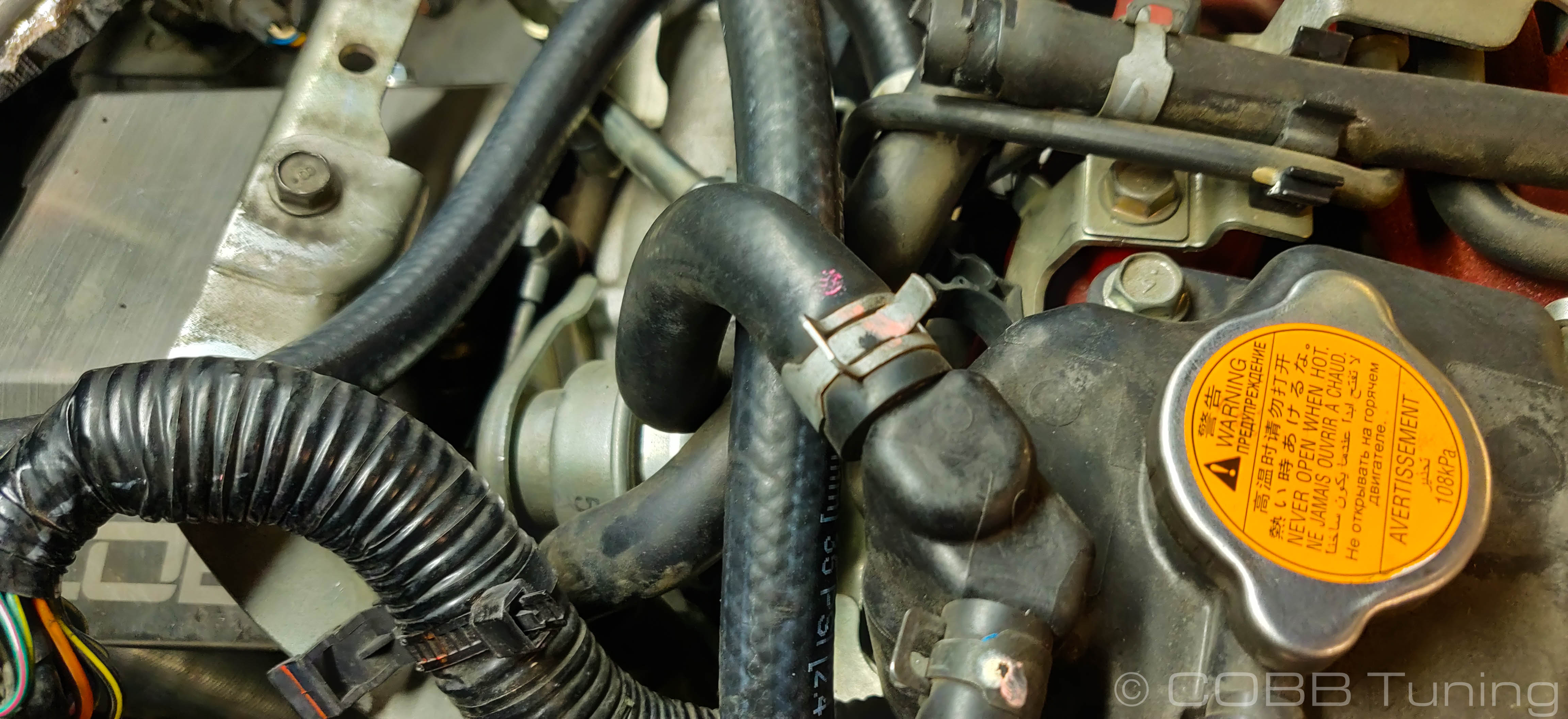
- Some coolant spillage is unavoidable, but clamping the line in the middle can help reduce this.
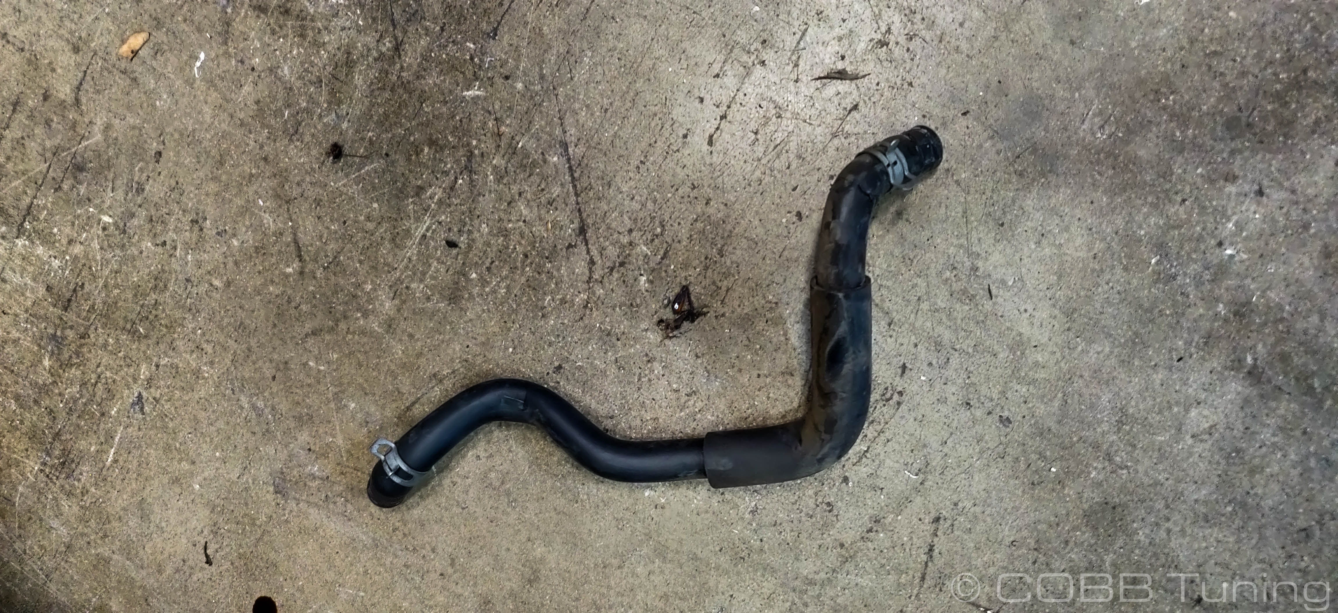
- Loosen the spring clamp and pop the cooling line off of where it goes into the top of the turbo.
- Route your lower cooling line from the AOS over to this spot and connect it using the provided spring clamps. You should now have the factory rubber hose only attached to the expansion tank, and the AOS lower coolant line attached to the upper coolant hose for the turbo.
Reference Fig.
Reinstall TMIC
- Reinstall the stock top mount intercooler in the reverse order of removal. You will not need to retain the stock metal pcv crossover tube as that has been replaced with properly rated hoses going to and from the AOS. Make sure to get the gasket for the BPV back in!
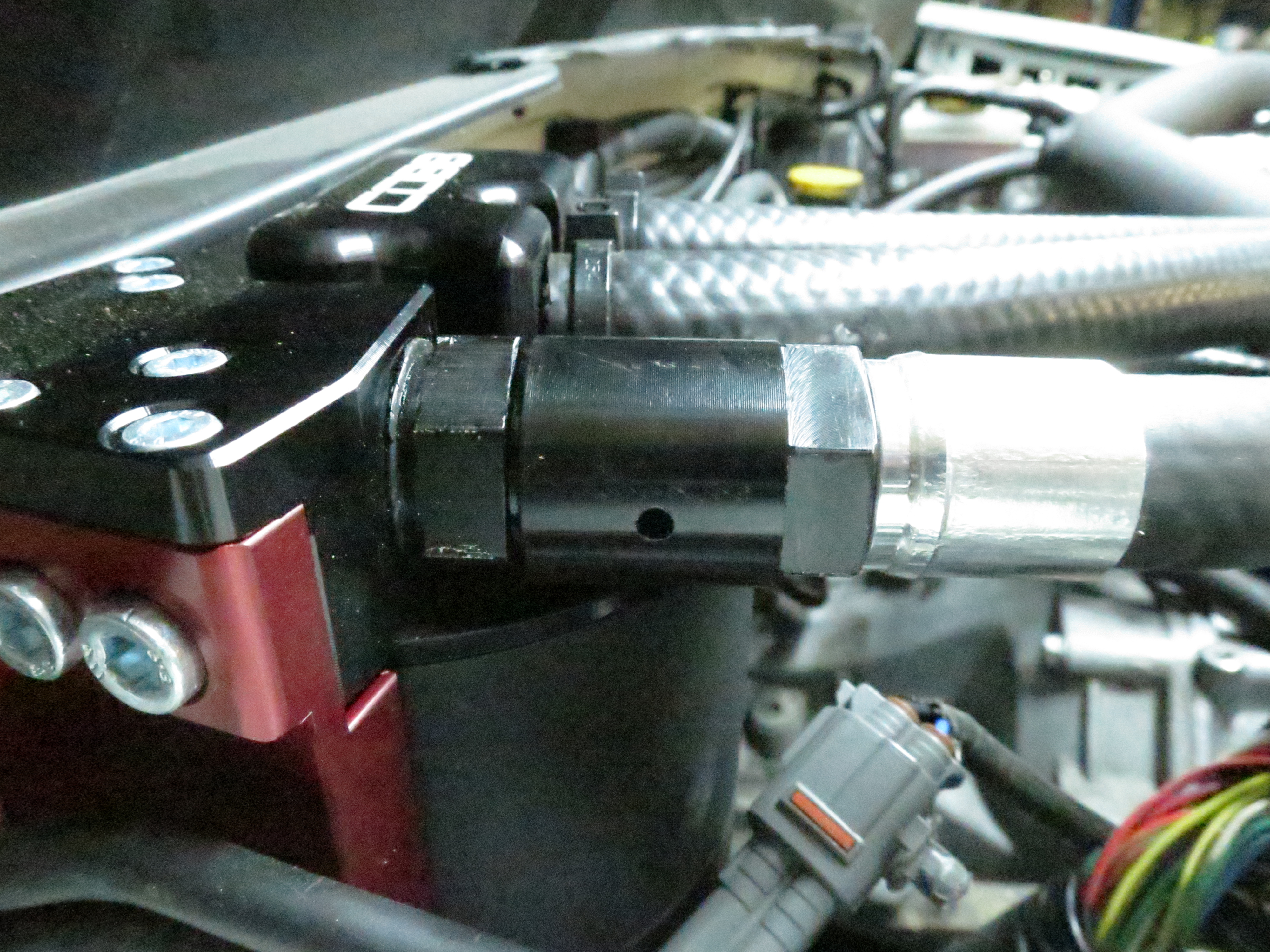
Upper Coolant Hose
- With the TMIC in place you can get a better idea of routing the upper coolant hose to minimize rubbing against the intercooler.
- Squeeze the upper coolant hose clamp where it attaches to the expansion tank. Remove the coolant hose from the car.

- Connect your upper coolant line to the Expansion Tank.
Reference Figure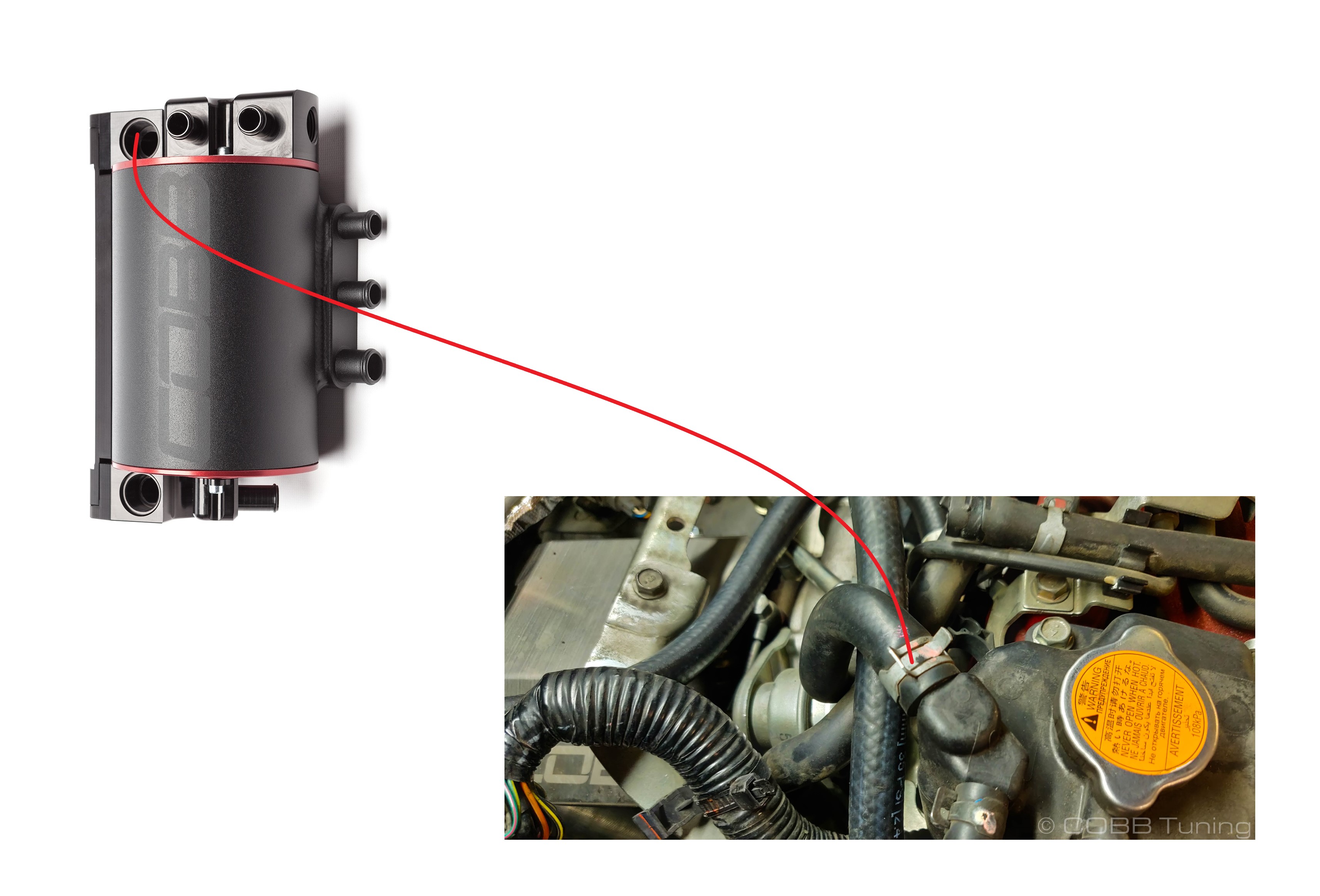
Coolant Bleeding Addendum
- Now it's time to bleed the coolant. Ideally you won't have lost a lot of coolant, however this is an important step and can get a little bit time consuming, however any pockets of air can cause issues with overheating or incorrect coolant temperature settings.
- The Upper Coolant hose on all of the COBB AOS units contain a small bleeder valve to make this easier. With the car cold but running, use a wrench to hold the fitting closer to the AOS and another to loosen the outer fitting which should allow coolant air to come out of the weep hole. Do this until no more air comes out.
- While not necessary bleeding the entire cooling system can ensure no air is still in the system. Using a coolant bleeding funnel like this one can make things a whole lot easier as they come with fittings to mount directly to the cap and allow the system to bleed and fill itself at the same time. (Shown on an STI but the process will be identical using a radiator cap)
Keep in mind that any coolant in the funnel will get just as hot as the rest of the coolant in the engine so use caution to avoid burns.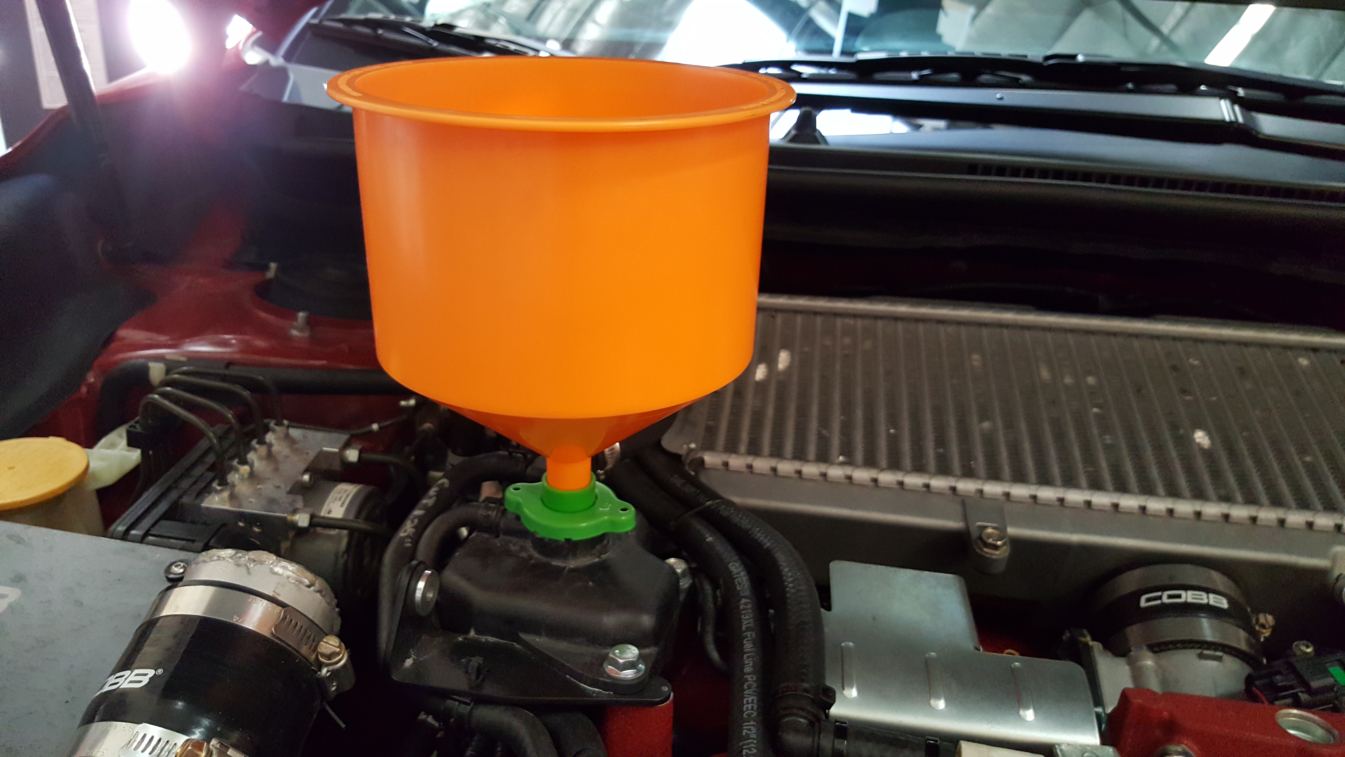
- With the system full turn on the vehicle and crank up the heater all the way. By having the heater on the coolant can circulate through the heater core which will remove air bubbles from that portion of the system. Make sure to keep an eye on your coolant levels at the tank or in the funnel so that the car doesn't add any more bubbles into the system.
- Once the coolant stops bubbling you're all done with the bleeding! This can take a while (it took around 30 minutes on our car). While it's bleeding make sure to keep an eye on the coolant temperature in order to make sure your car isn't overheating and that the fans are cycling on and off properly.
While idling the radiator will got very hot quickly, be careful to avoid burns.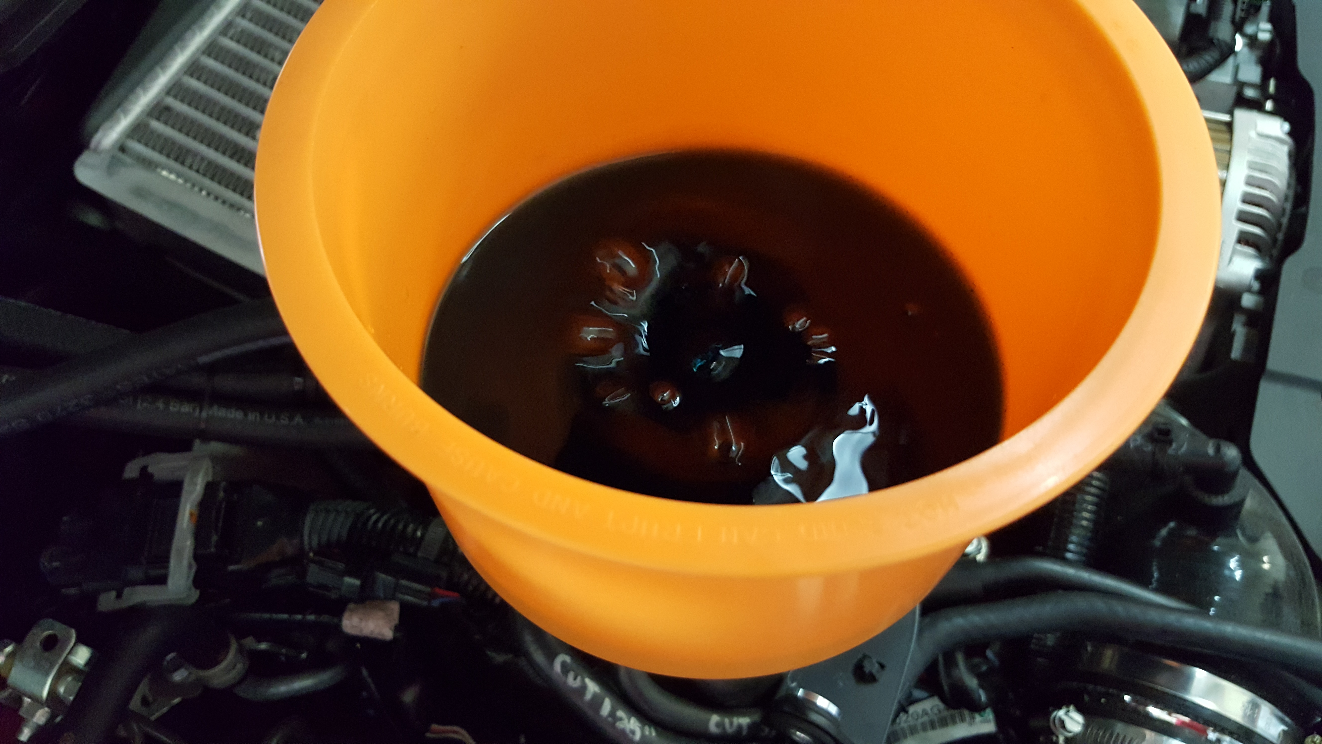
- Place the plug securely down in the funnel and remove it from the car. Put remaining coolant back in the bottle.
- Reinstall the Coolant reservoir cap.
Customer Support
Phone support available 9am to 6pm Monday-Thursday. 9am to 4pm Friday (CST)
866.922.3059
Copyright 2023 © COBB Tuning Products LLC. All Rights Reserved. | www.cobbtuning.com