7M1500 - COBB Tuning Ford Ecoboost Mustang FMIC

7M1500
COBB Tuning Ford Mustang Ecoboost FMIC
Ford Mustang Ecoboost 2015 - 2019
Congratulations on your purchase of the COBB Tuning Ford Mustang Ecoboost FMIC. The following instructions will assist you through your installation process. Please read them first BEFORE beginning the install and familiarize yourself with the steps and tools needed. If you feel that you cannot properly perform this installation, we HIGHLY recommend you take the vehicle to a qualified and experienced automotive technician.
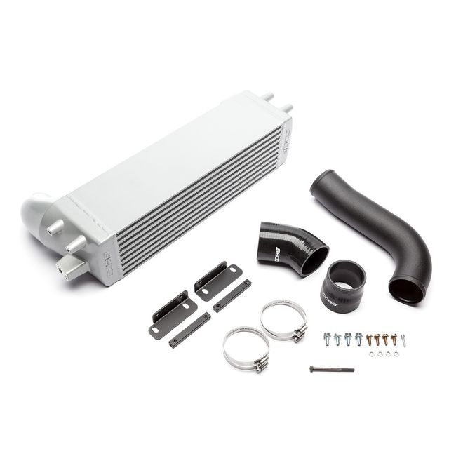
Part List
- Ford Mustang Ecoboost FMIC Core
- 3" Black Powdercoated "Cold Side" Tube
- 45 Degree 3" Silicone Hose
- 3"- 2.75" Straight Reducer Silicone Coupler
- 4 x #48 Hose Clamp
- 2 x FMIC Core Mounting Brackets
- 2 x Black Mounting Nut Plate
- 4 x M6x16mm Hex Bolt
- 4 x M8x16mm Hex Bolt
- 4 x 6mm Lock Washer
- M5x20mm Socket Head Cap Screw (MAP Sensor)
- M6x80mm Socket Head Cap Screw (Installation Tool)
- COBB FMIC Stencil
- COBB License Plate Frame
- 2 x COBB 6" White Stickers
Tools Needed
- Flathead Screwdriver
- 4mm Allen Wrench
- 1/4" or 3/8" Rachet
- 1/4" Swivel-Head Ratchet or 1/4" Universal Joint
- Various Ratchet Extensions
- 5.5mm Socket
- 7mm Socket
- 8mm Socket
- 10mm Socket
- 12mm Socket
- 10mm Box Wrench
- 12mm Box Wrench
- T25 Torx Bit
- Painter's Tape (If Using Stencil)
- Spray Paint of your Choice (If Using Stencil)
Removal of Factory FMIC
- If you plan to paint "COBB" into the front of your FMIC, now is the time to do it! Lay your included stencil onto the front of the FMIC core and secure it using painter's or masking tape, making sure to keep the stencil nice and tight on the face of the core. From there, apply a few coats of paint. Allow to dry for a little while before removing the stencil.
- To do this install, you'll at least want full access under the front of the vehicle. To do so, get the front of the car up on jackstands (be sure to block the rear wheels) or get the car up on a lift, if possible.
- Using a Flathead screwdriver or trim removal tool, remove the eight (8) plastic rivets from the cooling panel above the radiator.
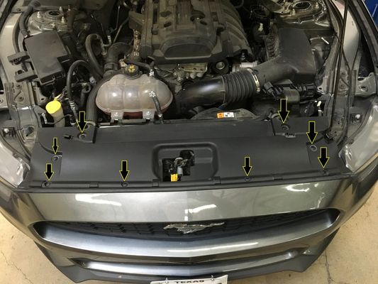
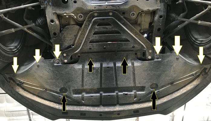
- Using an 8mm socket, remove the six (6) screws that line the top of the bumper, as seen with the vertical arrows below.
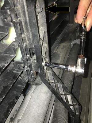
- Using a 5.5mm socket, remove the two screws that are covered up by the soft trim at the sides of the bumper, near the headlights. These are shown with the horizontal arrows above and further with the picture below.
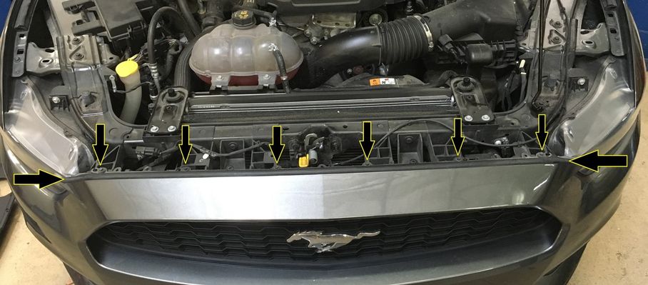
- That wraps up the top of the car. Now it's time to head under the car and remove the six (6) plastic rivets (white arrows) from the under-tray using a Flathead screwdriver. While you're there, use a 8mm socket to remove the four (4) screws (black arrows), as well. Set the under-tray aside for re-installation later.
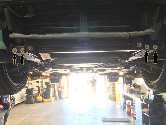
- Moving over to the inner fender well, you'll need to remove three (3) plastic rivets from each side. It may be easier to turn the wheel to gain more room for your tools. There are two (2) that are easily visible near the the bottom and middle of the front fender liner. There is a third rivet that is higher up towards the top that must be removed too.
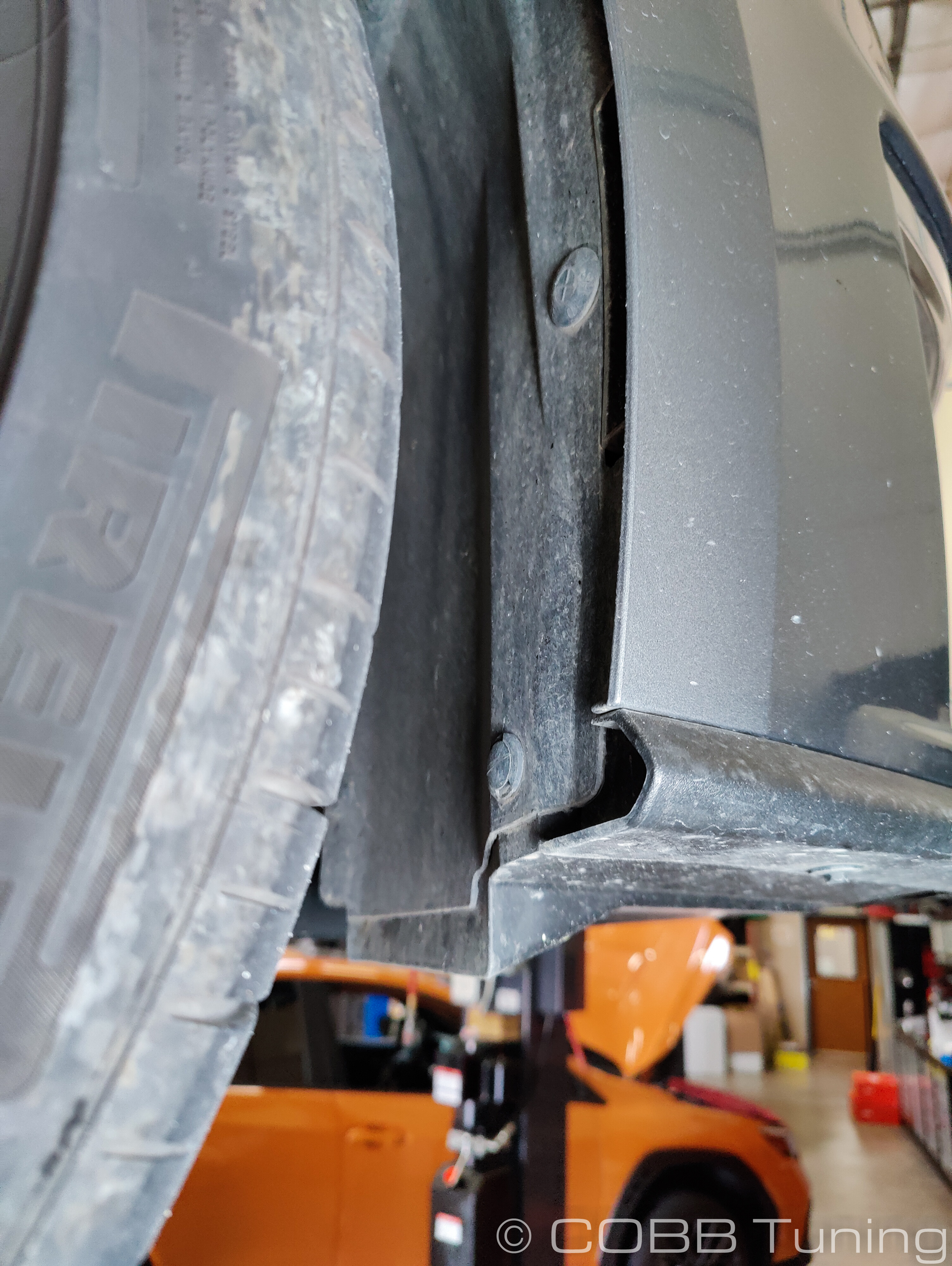
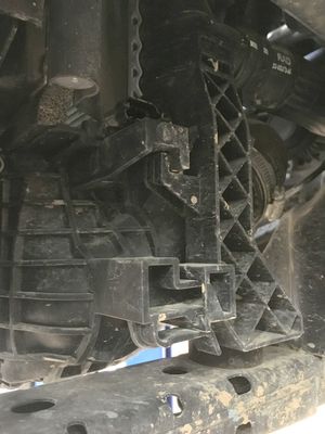
- Once the fender rivets are removed, you'll be able to pull back the plastic liner to access the fasteners connecting the fender to the bumper.
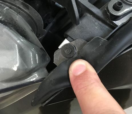
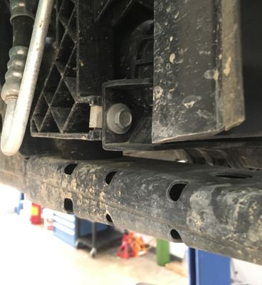
15-21 models A single 7mm bolt that is located up at the corner of each side of the bumper. This bolt holds the corners of the bumper to the front quarter panels. This needs to be removed completely on both sides before attempting to remove the bumper.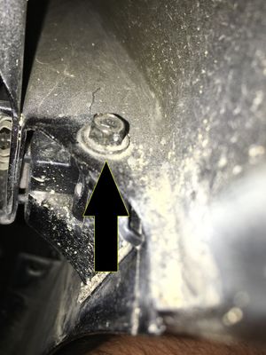
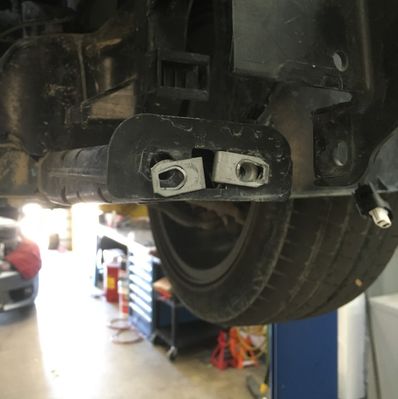
21-23 models a plate with two studs goes through the bumper up into the fender and is secured with two 10mm nuts. Use a 10mm wrench and scratch up your hands a little bit on the bumper to remove the nuts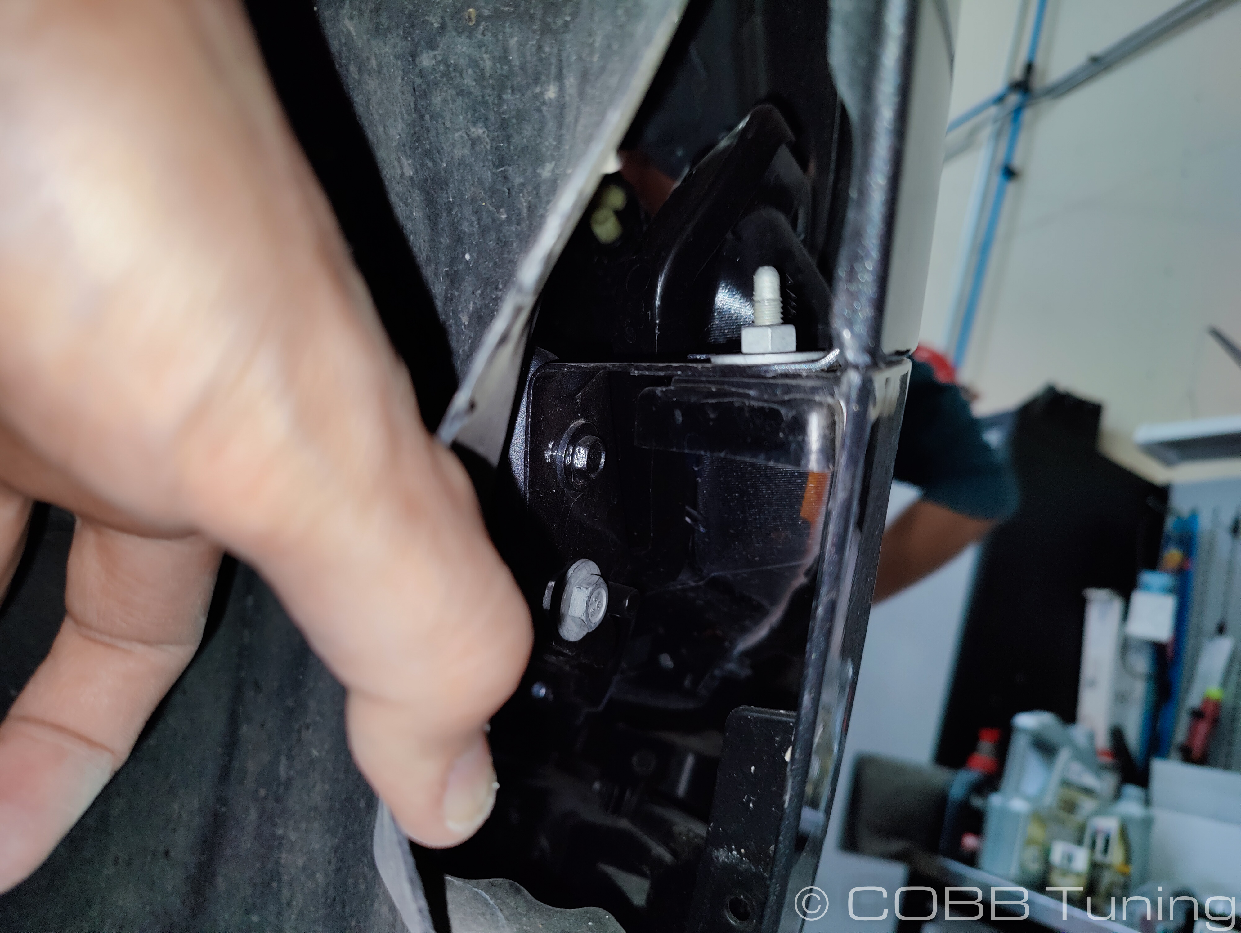
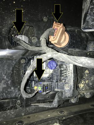
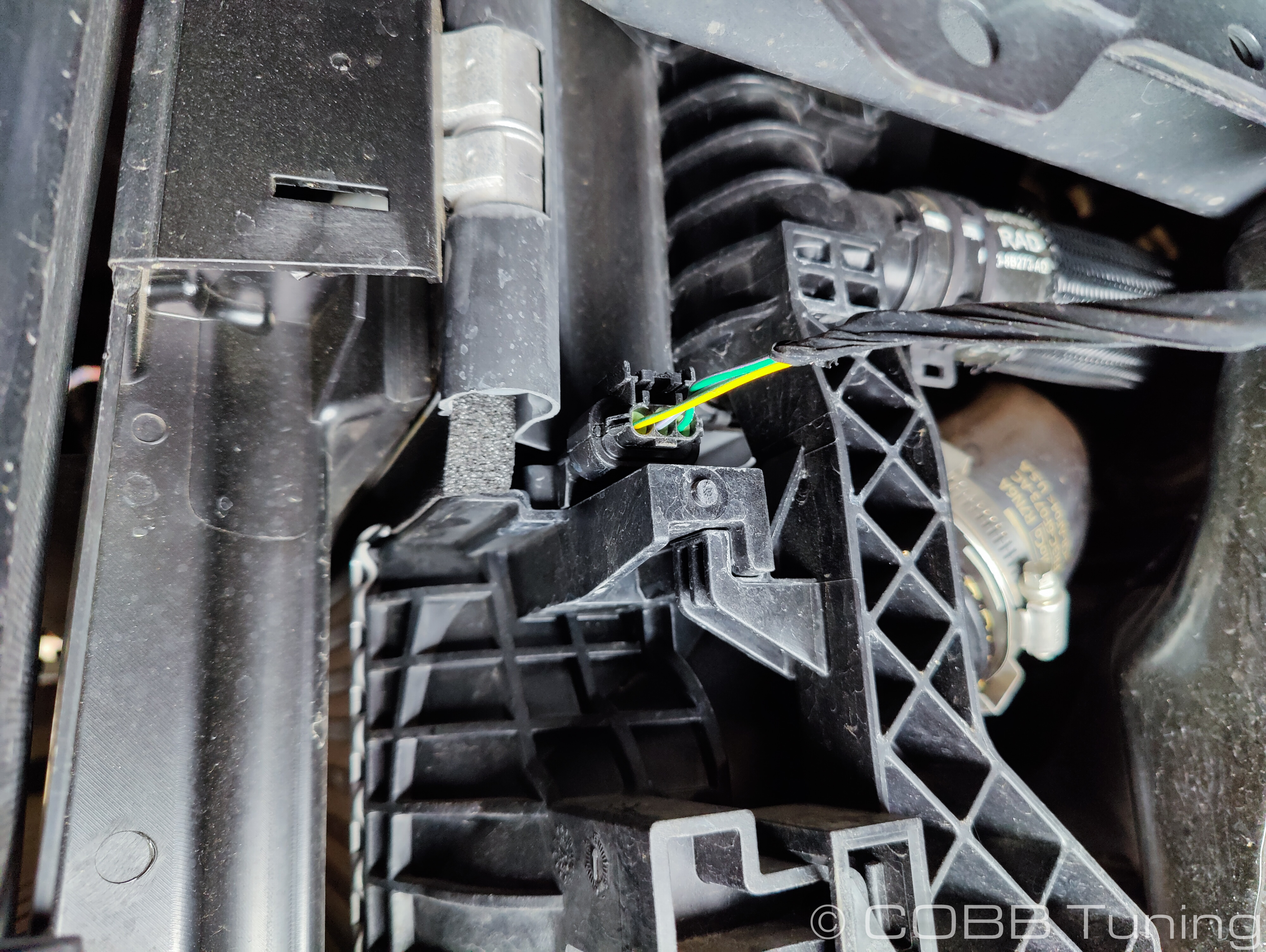
- With all the bolts removed from the bumper, the last thing to do is to disconnect the electrical plugs for the turn signals or fog light depending on what your car is equipped with and the year.
- To remove the bumper, carefully pull from the corner where the side of the bumper meets the quarter panel, on each side of the car. It will offer some resistance but should pop out. Once each side is loose, carefully lift the bumper up and away from the car and set on the ground, taking care not to scratch any paint.
- With the bumper out of the way, time to remove the factory grille shutters (if applicable). Use an 8mm socket to remove the four (4) screws that hold the middle and bottom of the shutters in place. On the back of the grille shutters, there is a 5.5mm screw that must be removed as well, before popping the rear actuation bar loose. The second picture below shows the 5.5mm screw location as well where to squeeze to release the actuator bar. Then, disconnect the grille shutter plug that is near the crash beam. Finally, using a Flathead screwdriver, pop loose the two (2) plastic rivets are the top of the grille shutter assembly. Remove the grille shutters and set them aside.
Note: We typically don't recommend reinstalling the grille shutters. With a performance car, we'd like to make sure the radiator and FMIC are getting as much cool air as possible, thus, no need for grille shutters.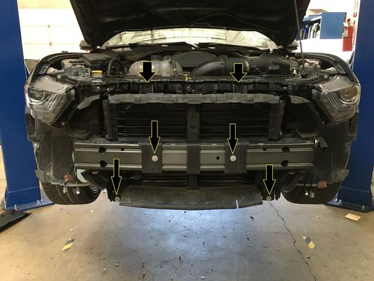
- With the grille shutters out, we need to remove this cross bar at the front of the frame rails. Use a 10mm socket to remove the four (4) bolts and set the cross bar aside.
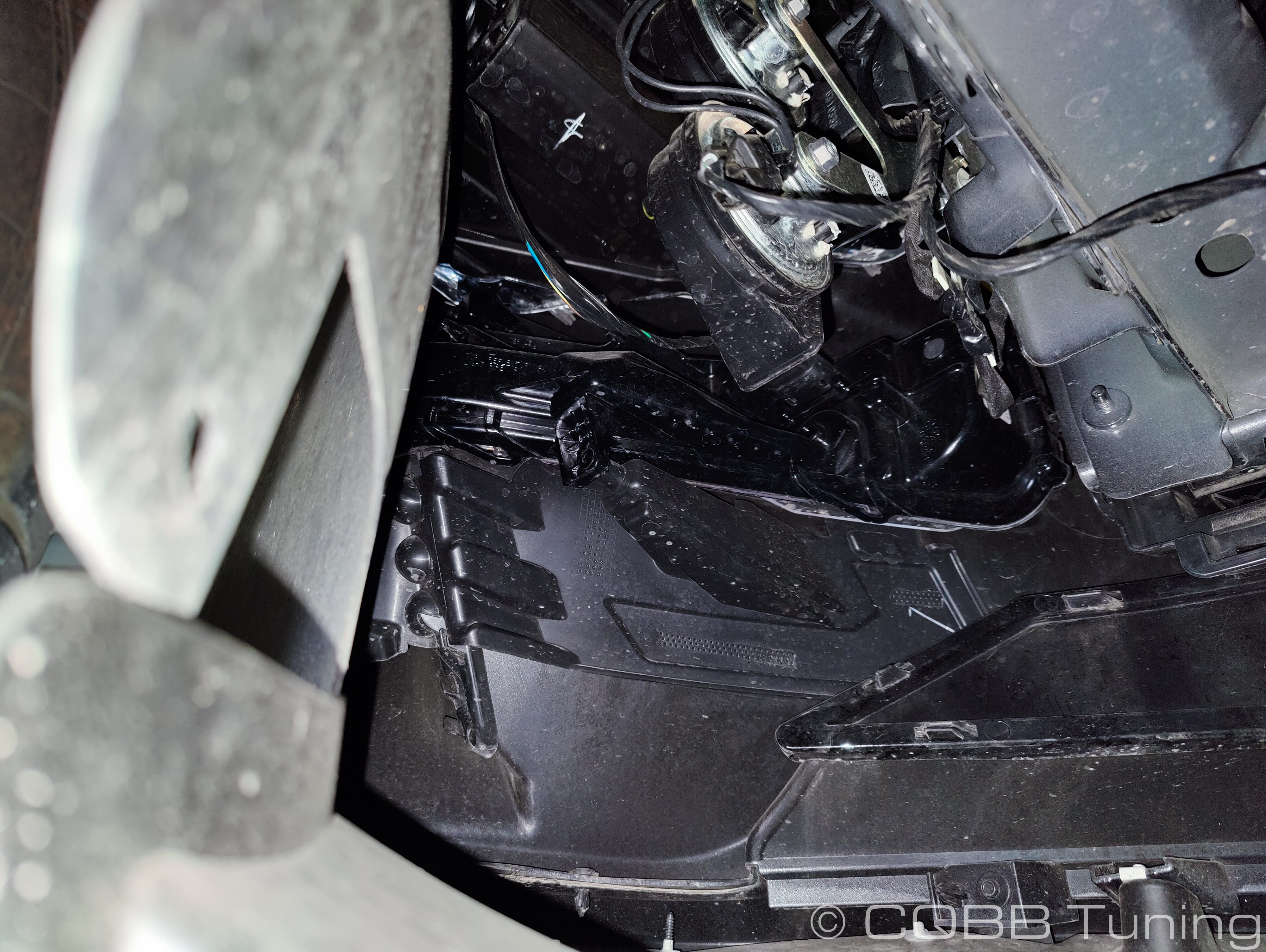
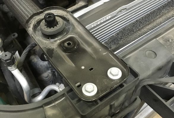
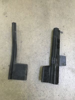
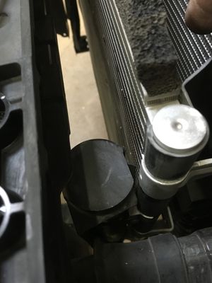
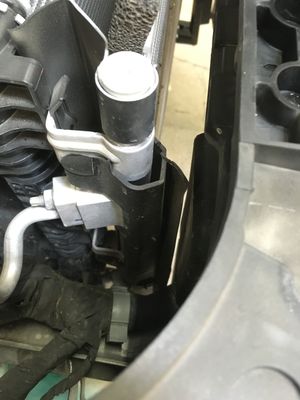
- Now, we'll need to remove two of the HARD plastic air deflectors on either side of the factory intercooler. The passenger side deflector is held in by several push-pin style fasteners that need to be pulled out. The driver's side has a clip system and also saddles over the condenser. To get them out, you'll need to first loosen and remove the upper radiator supports, as seen in the first picture below. There are two of these, one at the top of each side of the radiator. This will allow you to move the radiator and AC condenser forward and backward to get the required plastic panels removed. Below is the a picture of the plastic panels we want to remove.
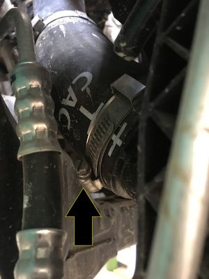
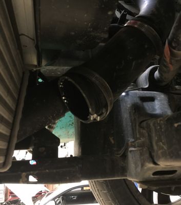
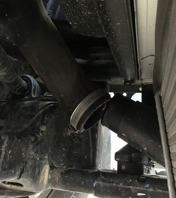
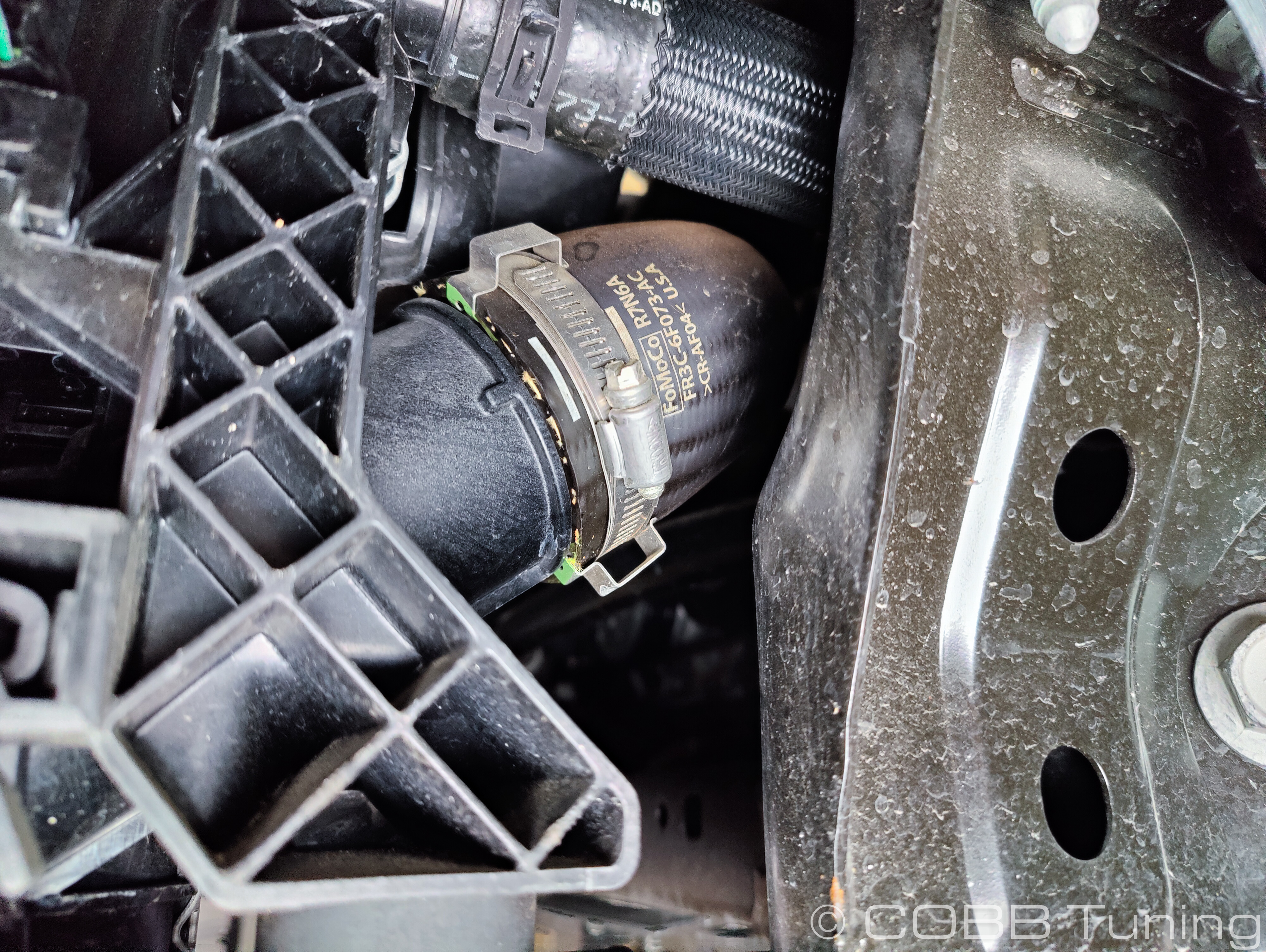
- With the panels removed, now it's time to finally remove the factory FMIC. Using a 7mm socket and extension, loosen the bottom most hose clamp that connects the passenger side charge pipe to the intercooler and pull it away from the intercooler. Bend it up and out of the way.
- Now, we'll want to loosen and remove the entire driver side charge pipe. Do so by using a 7mm socket and loosen and remove all clamps. Pull the piping connecting the intercooler to the throttlebody out and set it all aside. We don't need it anymore.
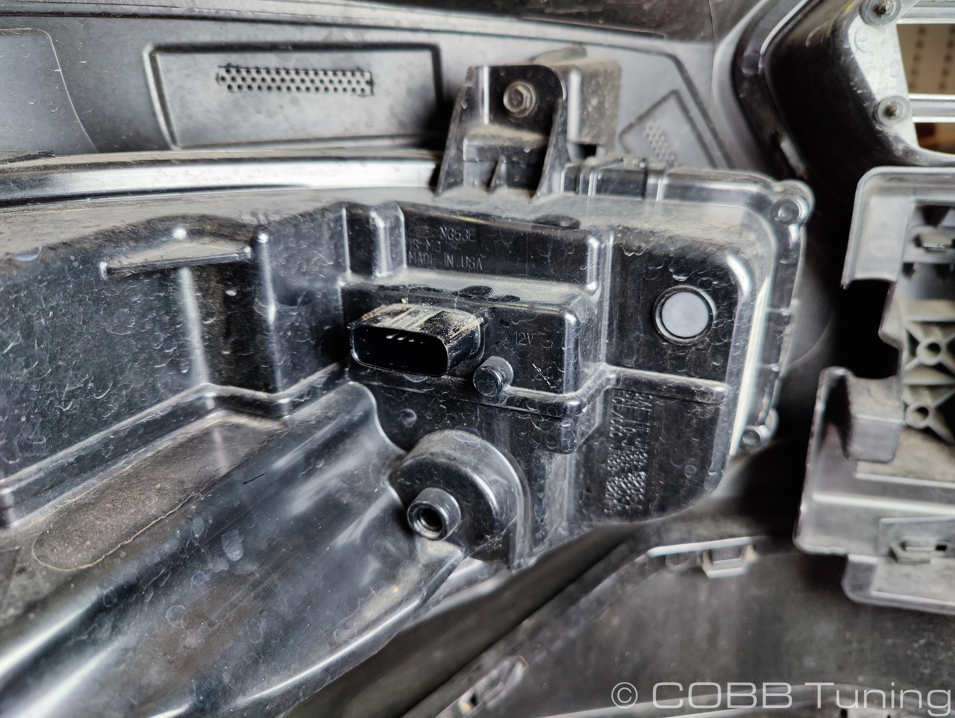
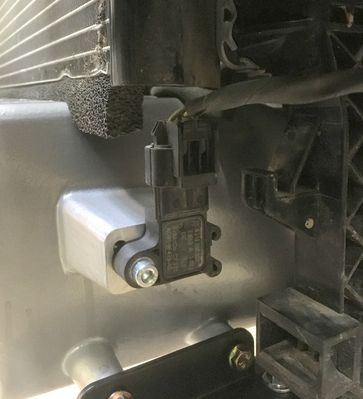
- Now is a good time to unplug the MAP sensor located on the driver's side of the intercooler.
- Using a 10mm socket, loosen and remove the forward facing bolt on the passenger side of the intercooler, as seen below.
- Now, on the driver side, there is clip system that you must unclip. From here, you should be able to start getting the intercooler removed. You may need to push back on the radiator, twist in all sorts of strange ways, but eventually, you'll get this FMIC out. Just take care not to damage any fins on the radiator or intercooler in the process. Just be patient, you'll get it!
Installation of COBB FMIC
- With the removal of your factory FMIC, now it's time to install the bigger, better, more mature COBB FMIC. To start off, go ahead and the remove the four (4) threaded fasteners that are left behind from the cross bar.
- Now, carefully install the COBB FMIC where the factory unit was removed from. Carefully rest the intercooler's mounting extrusions onto the top of the vehicles chassis. Be careful not to bump it or allow it to fall.
NOTE: Take care not to shove the COBB FMIC up into the radiator. Those fins bend really easily!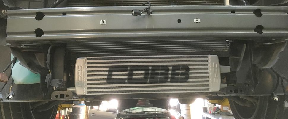
- Carefully fit the factory passenger side charge piping onto the COBB intercooler but don't tighten the clamp just yet.
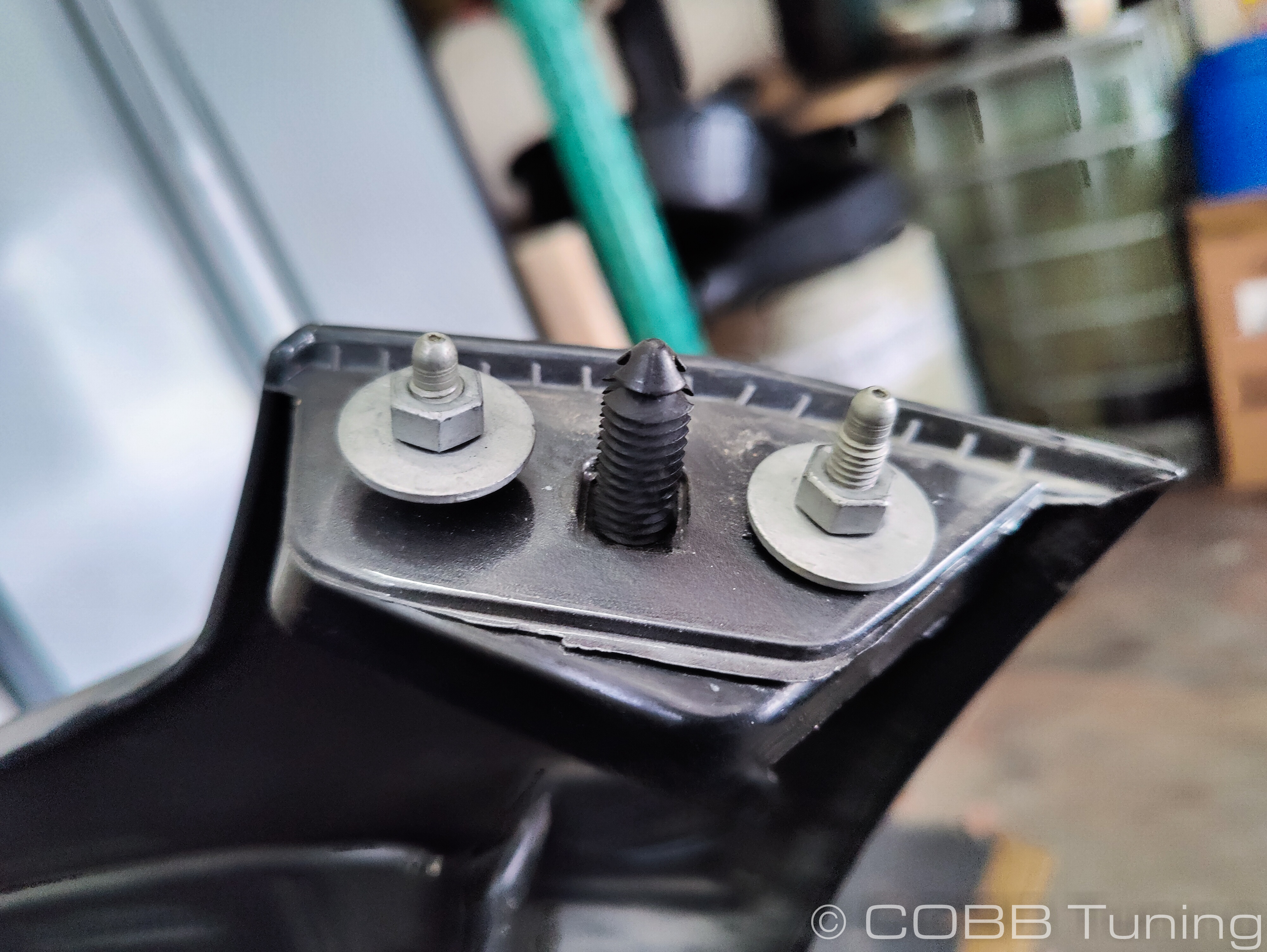
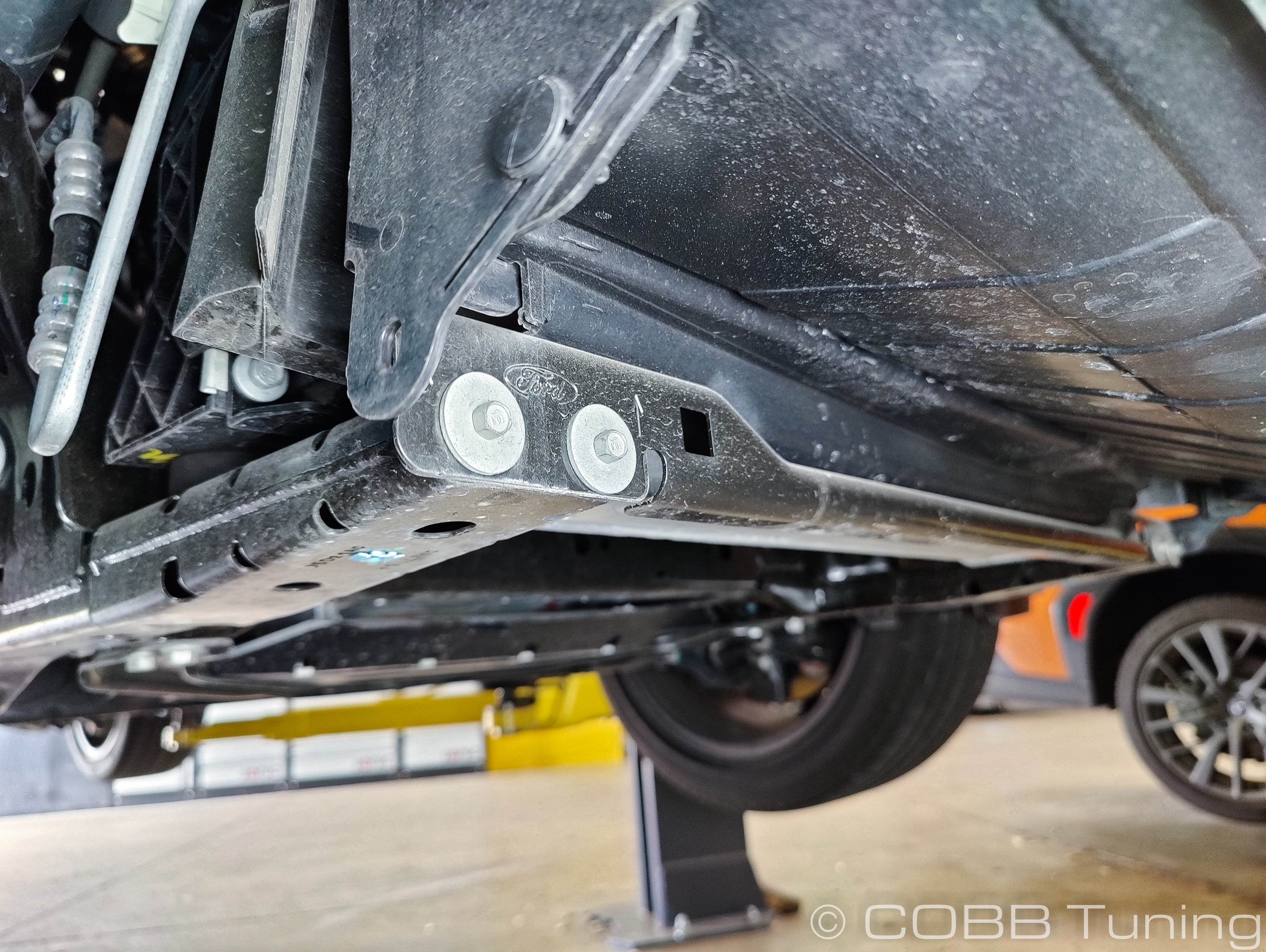
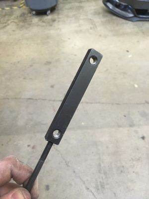
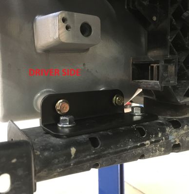
- Now, install the mounting brackets as shown below. The black nut plates are design to be installed INSIDE the rails that the intercooler is currently resting on. Use the long 80mm screw that was included in your kit as a tool to help hold the plate in place while you thread in the two (2) SILVER M8X16mm fasteners on each side. I recommend installing the vertical screws first to attach the brackets to the rails (using the nutplates), and then securing the intercooler to the brackets using the two (2) GOLDEN M6x16mm and 6mm lock washers on each side. To start off, just loosely install everything since we'll need to move things around before tightening down.

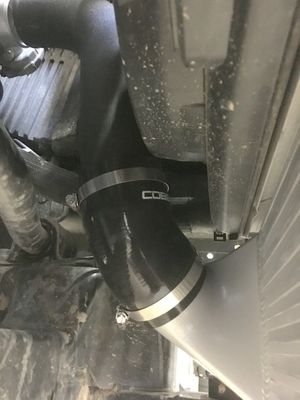
- Now that the intercooler is loosely bolted in place, we need to install the supplied 3" Throttle Body pipe (Cold Pipe). Install the 3" Silicone elbow first. With some suggestion, the 3" aluminum pipe can be coaxed into a perfect fit. Then install the straight coupler onto the pipe and throttlebody. Refer to the picture below as to the best way to install the 3" silicone elbow. The COBB should be upright and forward facing. Install a clamp on each end of each coupler. Leave them loose for now.
- At this point, your intercooler is fully installed, just loosely. Now is when you need to take some time to make some adjustments to how the piping is fitting onto the intercooler, where the brackets are located, etc. The intercooler fits the best when it is positioned as far back as possible. So, while watching out for all contact points, push the intercooler backwards towards the car until it stops. Then, see where it's contacting and see if you can work it to the side at all to gain more room.
- With the intercooler pushed back as far as possible, start snugging down the mounting brackets bolts using a 10mm and 12mm wrench, checking to make sure the unit doesn't move while you snug things down.
- Once the core is firmly tightened down to the chassis, go back and tighten up all the hose clamps, securing the charge piping to the intercooler core. Don't overtighten and strip the clamps!
- Finally, use a T25 Torx bit to remove the MAP sensor from the factory FMIC. Install the MAP sensor into the hole on the driver's side of the COBB unit with the supplied 5mm Socket Head Cap screw and a 4mm Allen Wrench.
- Hooray! Your COBB FMIC is now fully installed!
- Go back and reinstall all the parts in the reverse order they were removed.
A. If you'd like to maintain your grille shutters, they should fit just fine. However, we don't like 'em!
B. To reinstall the "cross bar" that bolts to the front of the rails that the FMIC is mounted to, you'll need to either trim some metal away on the bar or flip it around backwards/upside down. You can also just leave it off, if you'd like.
C. DON'T FORGET TO REINSTALL THE UPPER RADIATOR SUPPORTS! - Now, go out and enjoy your new, cooler breathing Mustang! Don't forget to flash to the correct map on your Accessport!
Links
COBB Product Install Instructions for Ecoboost Mustsang
Main Installation Instruction Repository for Mustang EcoBoost Parts
Map Notes for Ecoboost Mustang
Link to Mustang EcoBoost Map Notes to see what map you should be on given the parts you've added
COBB Customer Support Web Support and Tech Articles: COBB Tuning Customer Support Center Email: support@cobbtuning.com Phone support available 9am to 6pm Monday-Thursday. 9am to 4pm Friday (CST) 866.922.3059 return to www.cobbtuning.comContact Us:
Copyright 2023 © COBB Tuning Products LLC. All Rights Reserved. | www.cobbtuning.com