712400 - COBB Subaru Silicone Turbo Inlet Install [Discontinued]

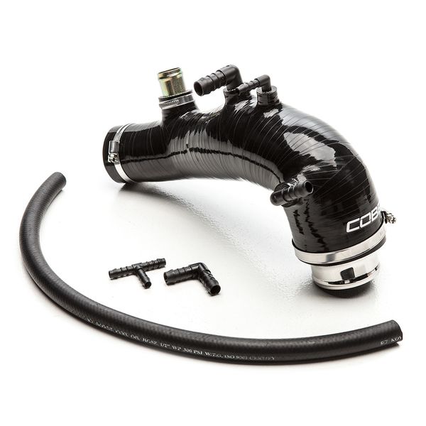
712400-BK – COBB Silicone Turbo Inlet
GR/VA STI
Congratulations on your purchase of the COBB Tuning Subaru Silicone Turbo Inlet! The following instructions will assist you through the installation process. Please read them BEFORE beginning the install to familiarize yourself with the steps and tools needed. If you feel you cannot properly perform this installation, we HIGHLY recommend you take the vehicle to a qualified and experienced automotive technician.
NOTE: This methodology of installing a turbo inlet hose is more involved, as we remove the intake manifold. However, due to our turbo inlet hose being packaged with fuel system upgrades, removing the intake manifold streamlines the install of fuel injectors, and thus, we prefer this approach.
IMPORTANT! Installing this kit will require custom tuning or utilizing an appropriate Stage Power Package map if you have a matching mechanical configuration. Please consult with COBB or an authorized ProTuner in your area.
Parts List
- Silicone Turbo Inlet
- 23" PCV Hose
Tools Needed
- Phillips head screwdriver
- Flathead screwdriver
3/8" ratchet
1/4" ratchet
1/4" 6" swivel ratchet
1/4" 10mm socket
1/4" 6" extension
3/8" 10mm socket
3/8" 12mm socket
12mm box end wrench
6mm hex key
- WRX 2002 - 2007
- WRX STI 2004 - 2020
- Forester XT 2004 - 2008
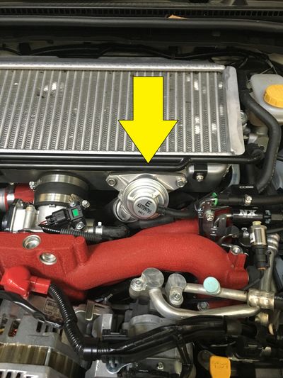
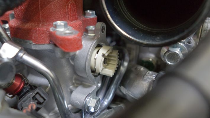
- Locate your stock bypass valve.
- Using a pair of pliers, remove the return line from the bypass valve.
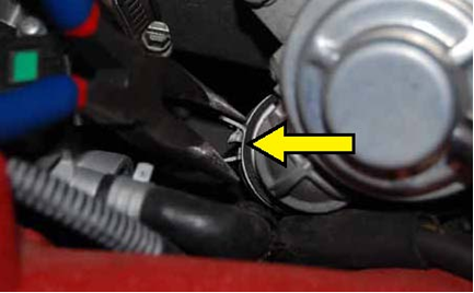
- Remove the vacuum line from the factory bypass valve.
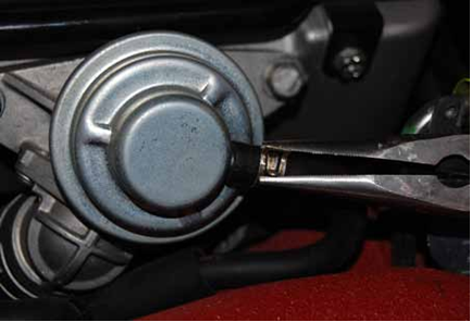
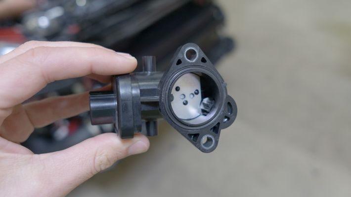
Using a 12mm socket with ratchet, remove the 2 bolts that hold the bypass valve in place and remove it from the car.
TIP: Make sure to keep an eye on the factory gasket behind the BPV. It can fall when you remove the valve and end up in difficult to reach locations!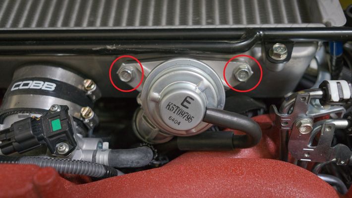
- Remove the bypass valve.
- Remove breather tubes from intercooler. Dikes can be helpful when removing the metal clamps or zip ties.
- Loosen the turbo outlet clamp using a screwdriver or appropriately sized socket (Typically 7-8mm) along with the (2) throttle body clamps using a screwdriver or 8mm socket.
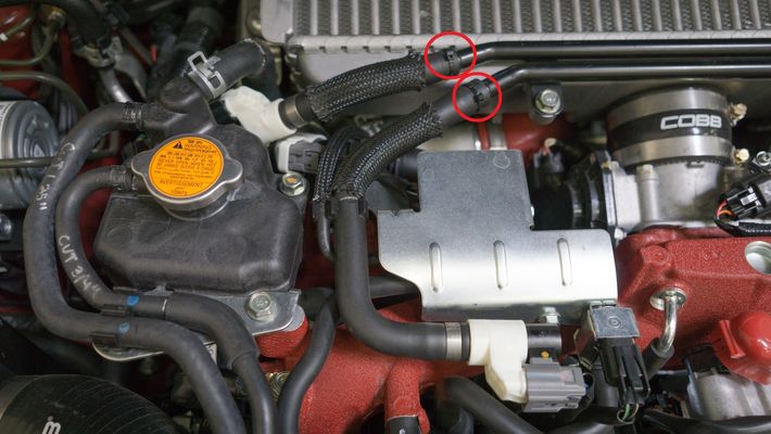
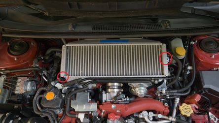
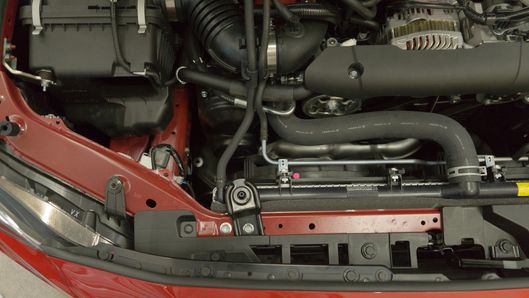
- Remove the two bolts holding the intercooler in place
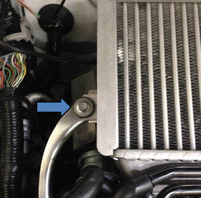
- Gently wiggle TMIC free from engine bay by sliding it back and then out. Be careful to not damage your windshield wiper cowl.
- Remove the (2) plastic retainers that hold down the intake snorkel using a flat head screwdriver.
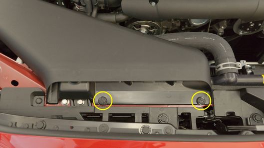
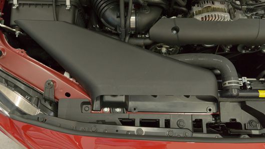
- Remove the intake snorkel from the engine bay.
- Remove the (2) Phillips head screws holding down the MAF sensor using a Phillips head screwdriver.
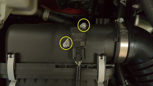
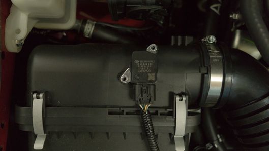
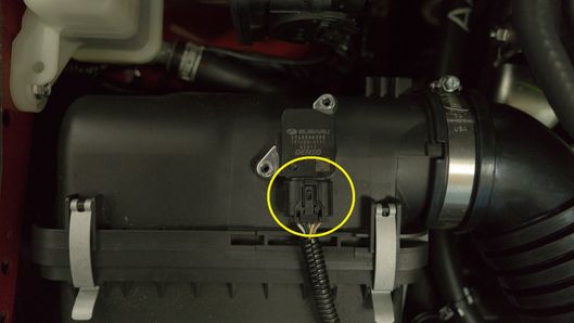
- Gently remove the MAF sensor and unclip the MAF sensor harness then set the sensor somewhere safe.
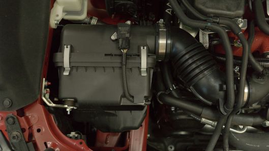
- Release the vacuum hoses from the clips on the intake elbow.
- Loosen the (2) hose clamps on the intake elbow.
- Remove the 10mm bolt that holds the bottom of the airbox to the chassis using a 10mm socket and 6" extension.
- Remove the 10mm nut holding the airbox to the airbox bracket.
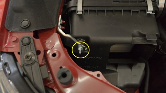
- Gently lift and remove the airbox, being cautious of the other vacuum hoses in the engine bay.
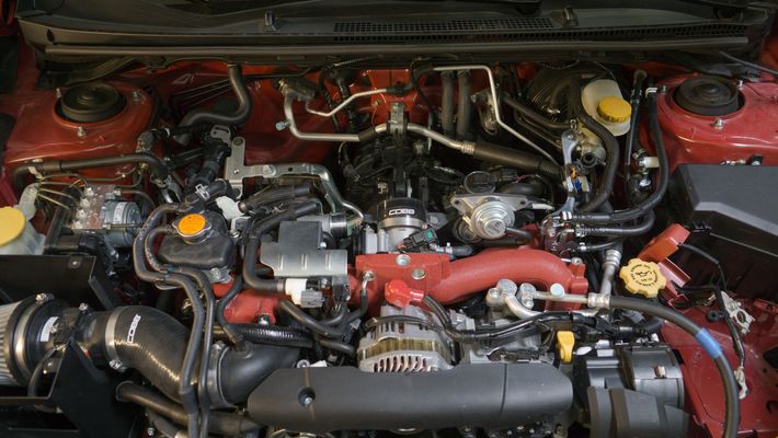
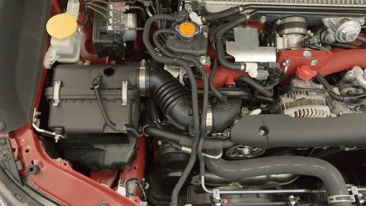
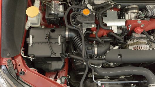
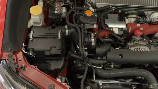
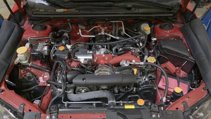
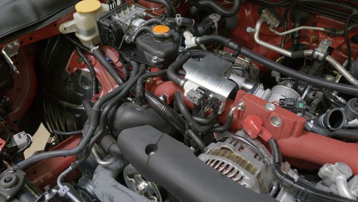
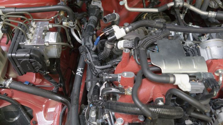
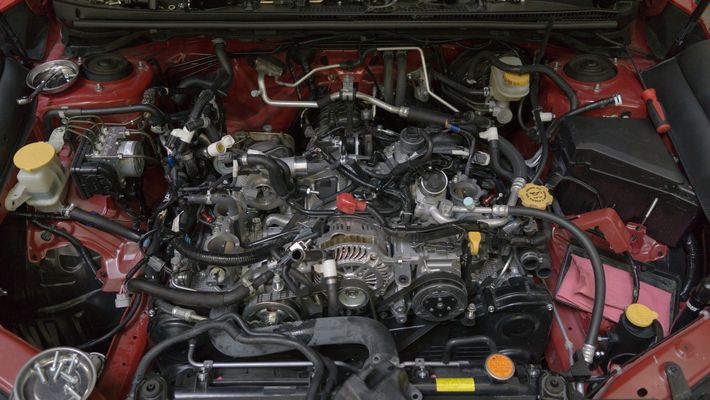
We perform this removal on a 2017 STI. While this is incredibly similar to the other models of EJ engines used over the years there may be small differences from vehicle to vehicle.
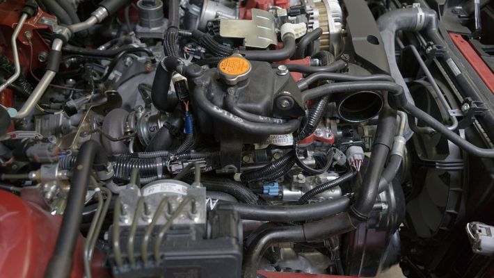
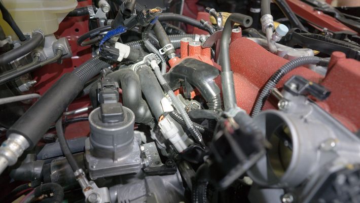
- You'll want to begin by taking plenty of pictures of your vacuum hose routing. This will be critical for when you're putting everything back together.
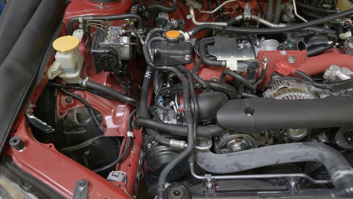
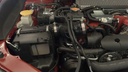
- With the car cool to the touch, we recommend draining the overflow coolant overflow reservoir. There is a small Phillips head bolt on the passenger side of the bottom of the radiator.
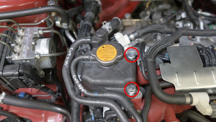
- Remove the coolant overflow reservoir by removing the (2) 12mm bolts.

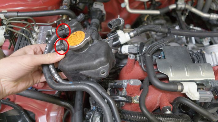
Remove the top and bottom coolant lines going to the overflow reservoir using a pair of pliers.
Using a proper hose clamp can help reduce any spillage of fluids and reduce the amount of time required to bleed the cooling system later on.
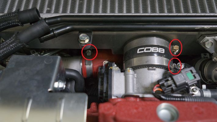
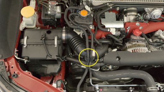
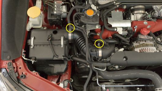
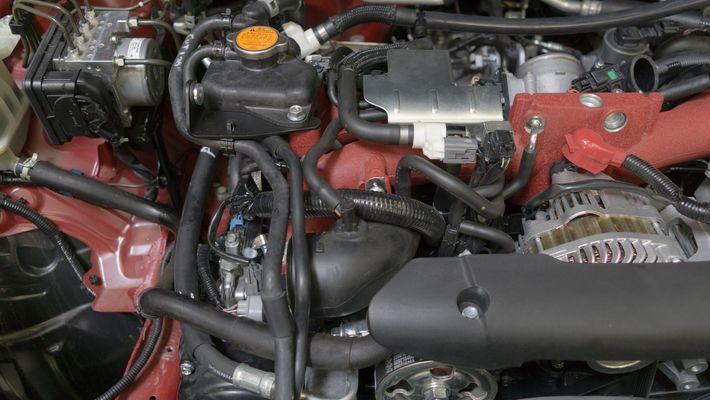
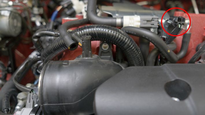
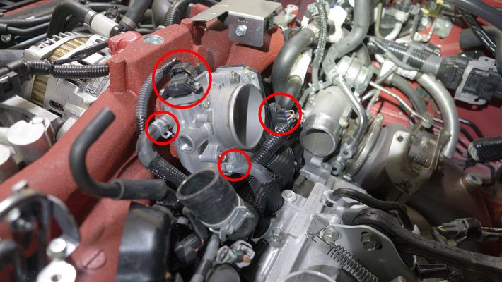
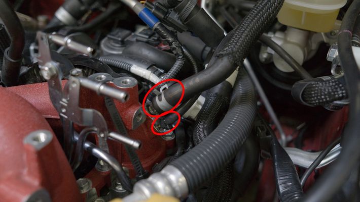
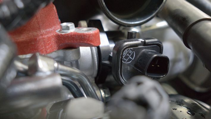
- Disconnect the electronic boost control solenoid (EBCS). There will be (3) connection points, 5/16" line to the turbo inlet hose, a 1/4" line to the wastegate, and an electrical harness (blue).
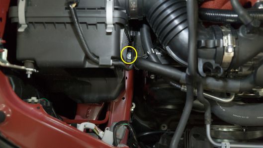
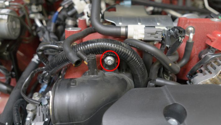
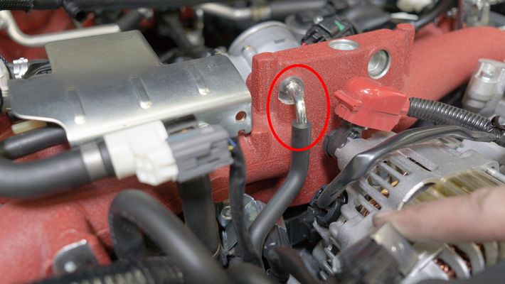
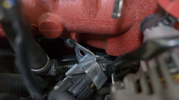
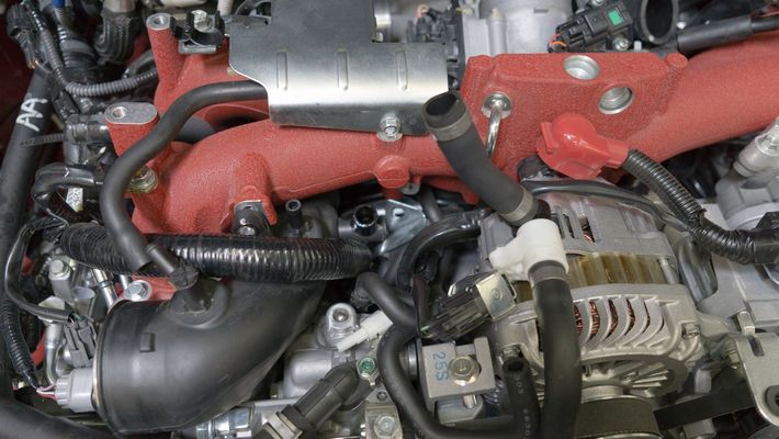
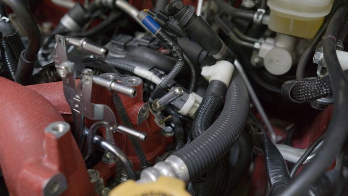
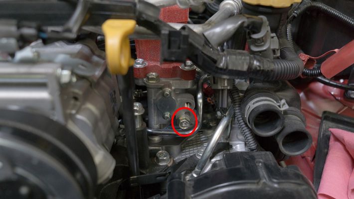
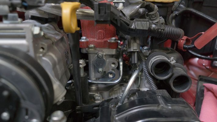
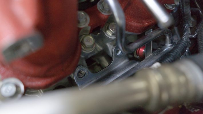
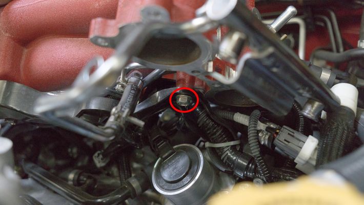
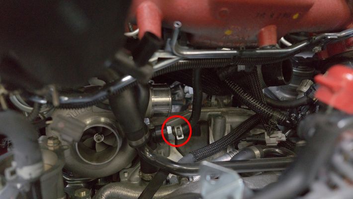
- Remove the 6mm hex head bolt on the front of the intake manifold holding the turbo inlet on.
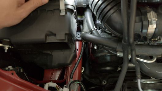
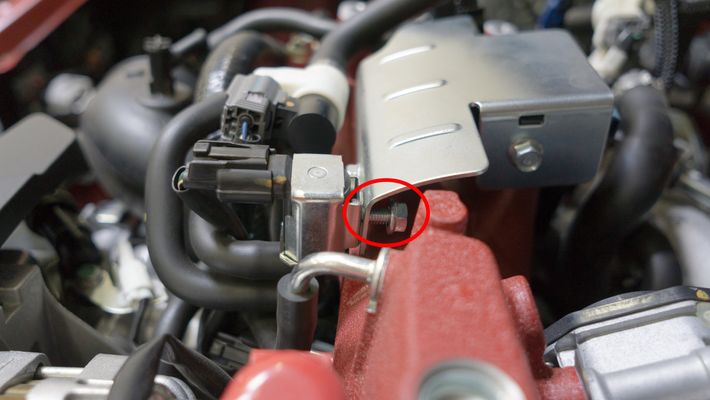
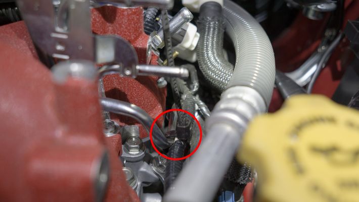
- Remove the 10mm bolt on the rear of the EVAP sensor.
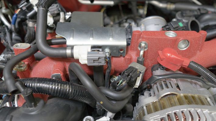
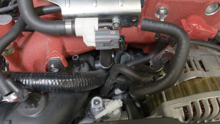
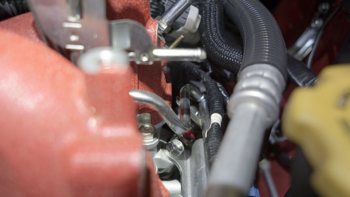
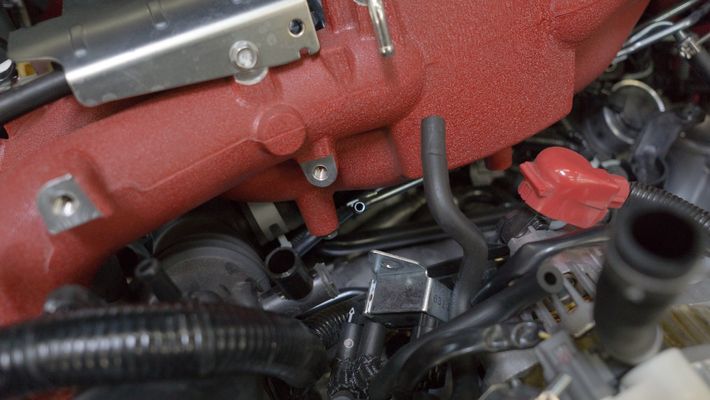
- Remove the intake manifold vacuum line.
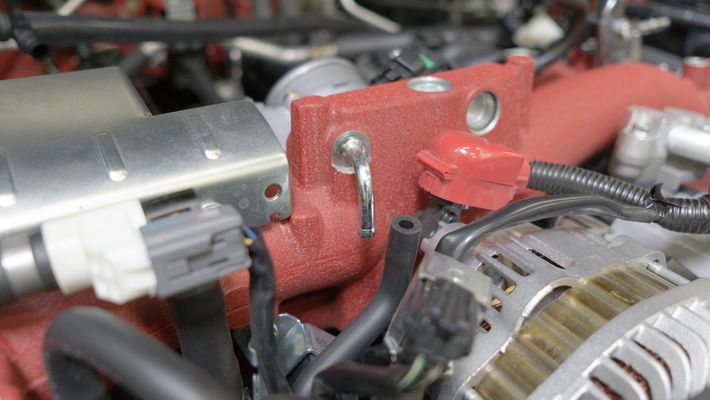
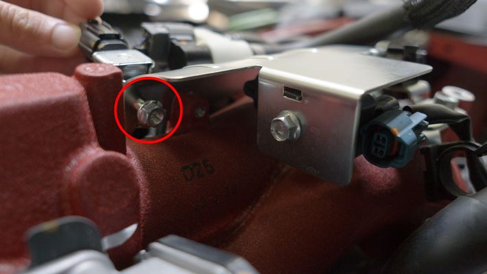
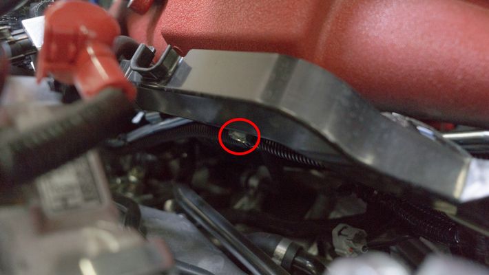
- Remove the 12mm bolt holding the purge valve on the intake manifold.
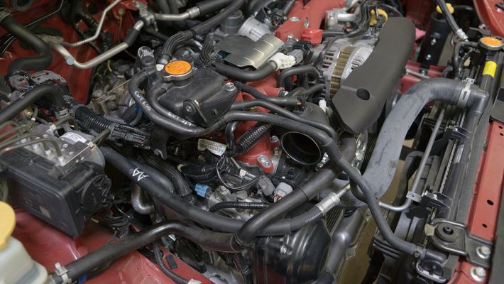
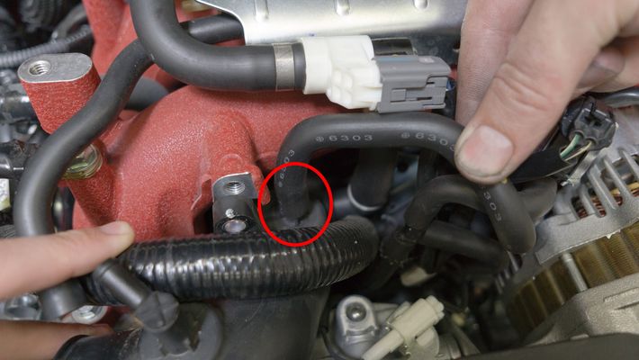
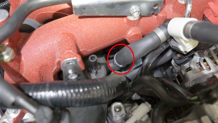
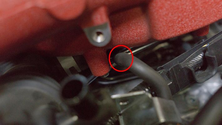
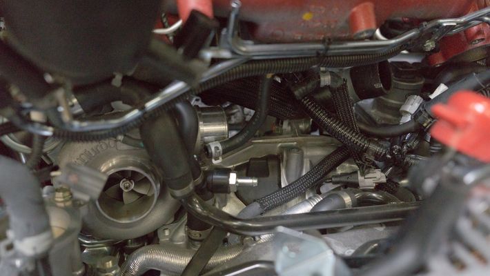
- Disconnect the 3/8" vacuum line from the top of the turbo inlet hose.
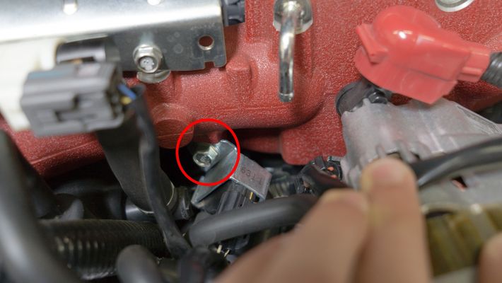
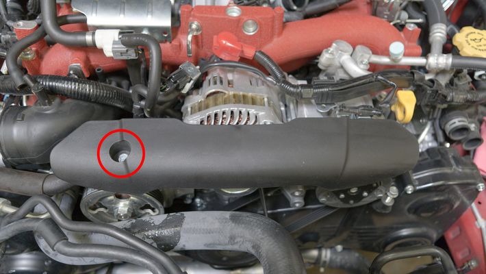
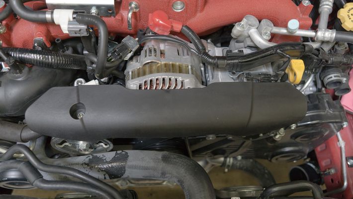
- Remove 10mm bolt securing the alternator cover. There is a push-type connector on the underneath the right-hand side.
- Remove the PCV hose from the turbo inlet hose. You may need to cut off a metal clamp that is installed from the factory.
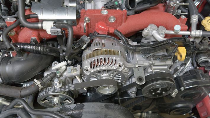
- Loosen the 10mm clamp securing the turbo silicone to the turbo.
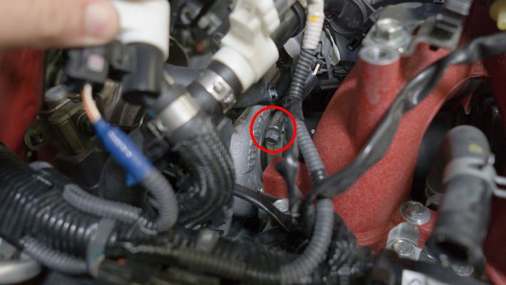
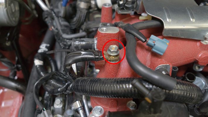
- Disconnect the 12mm bolt securing the ground.

- Remove the zip tie holding the wiring harnesses together.
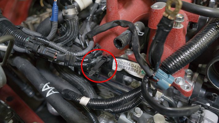
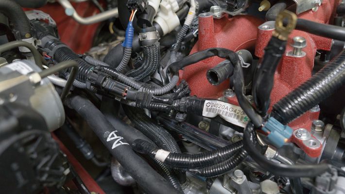
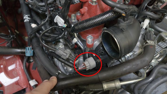
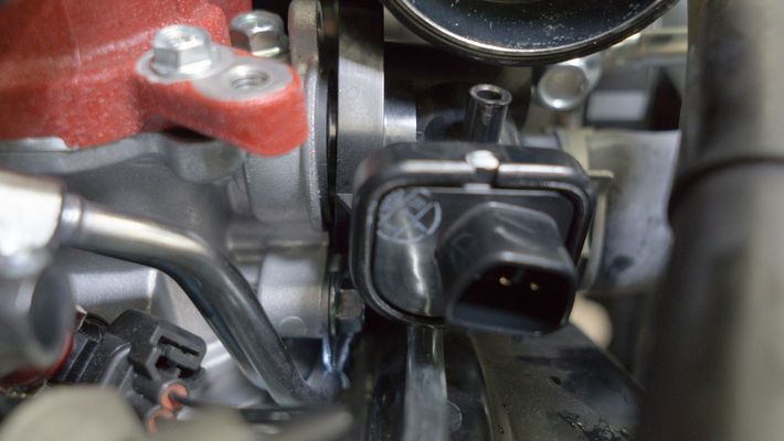
- Disconnect the MAP sensor, throttle position sensor wiring harness, and upper and lower coolant hoses.
- Disconnect the 12mm retainer bolt for the electrical harness on the back of the intake manifold.

Disconnect the fuel lines from the intake manifold.
We typically recommend marking the lines with some sort of tape or colored zip tie to ensure you put them back in the same place.
- Disconnect the brake booster hose and the fuel pressure regulator reference.
- Remove the zip tie holding the wiring harness to the fuel rail.
- Remove the 12mm bolt from the fuel rail bracket to the TGV.
- Remove the TGV electrical harness.
- Remove the (2) 10mm bolts holding the TGV to the manifold.
Gently and carefully remove the TGV from the manifold.
BE CAREFUL TO VERIFY THE POSITION OF THE GEARS AND DO NOT DAMAGE THE O-RING. It helps to take a picture in order to verify its orientation. or mark it using a marker. This needs to be back in the original orientation when you go to put it back together.
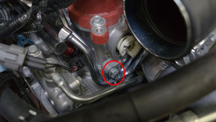
- Remove the 12mm bolt holding the fuel line to the manifold.
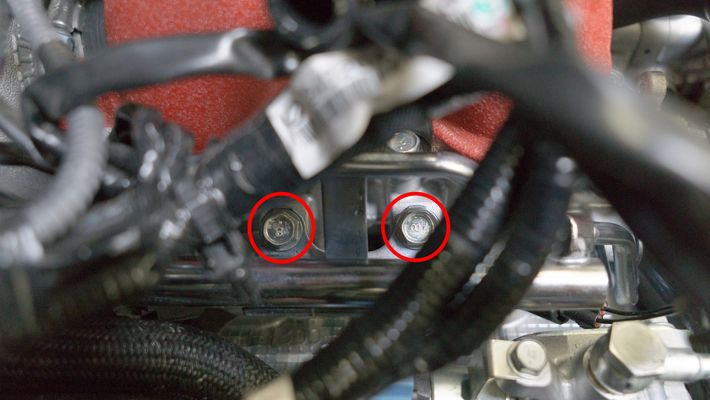
- Remove the (2) 12mm bolts holding the fuel rail on the passenger side.
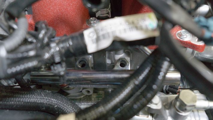
- Remove the (2) 12mm bolts holding the fuel rail on the driver's side.
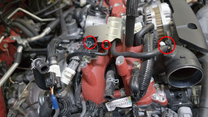
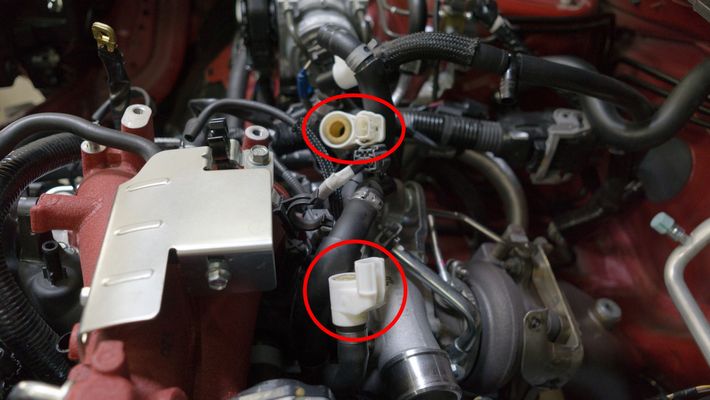
- Disconnect the (2) PCV hoses
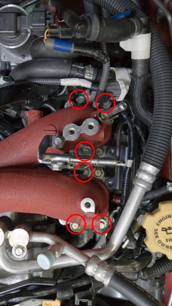
- Remove the (6) 10mm bolts securing the intake manifold on the passenger's side.
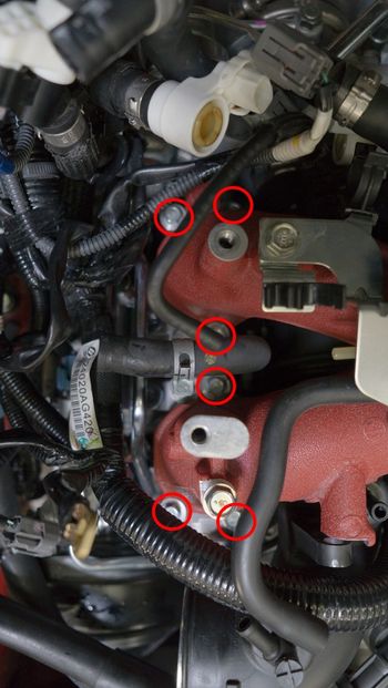
Remove the (6) 10mm bolts securing the intake manifold on the driver's side
After the bolts are loose, you can use a magnet to remove them easier.
Gently lift the fuel rail, pushing down on the injectors to keep them seated. You cannot completely remove the intake manifold yet. This step is for gaining clearance to the underside, so do not force it.
A small amount of fuel will spill, so it's a good idea to have a rag handy to catch it.
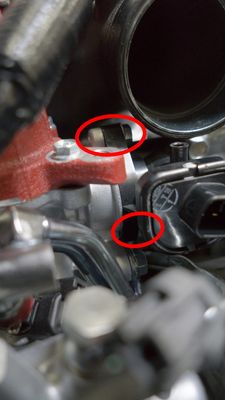
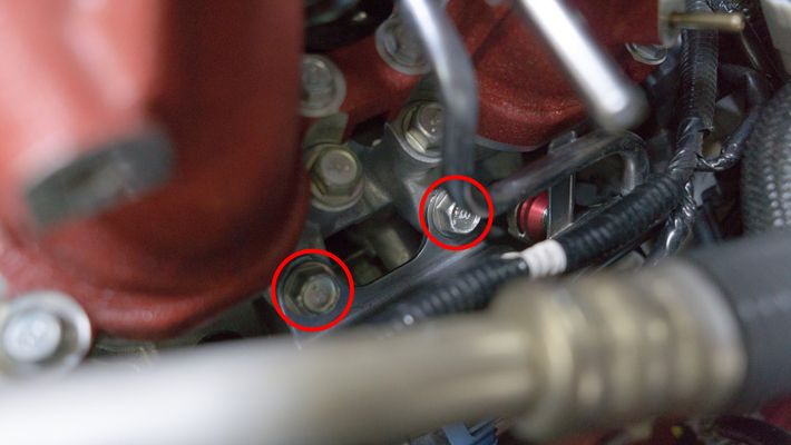
- After you've lifted the intake manifold slightly, there will be (2) 12mm bolts underneath that you need to remove. (1) is on the underside-middle, the other is on the underside-driver.
- Disconnect the vacuum line from the passenger side of the intake manifold.
- There is one remaining vacuum line that you will need to remove near the backside of the intake manifold.
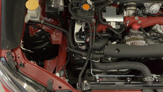
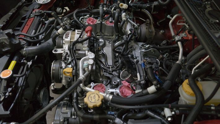
Gently remove the intake manifold. Be cautious of the TGV gears and the (2) intake manifold gaskets.NOTE: You may need to move the wiring harnesses around to allow clearance for the intake manifold.
Once removed, we recommend covering the exposed ports to prevent foreign material contamination.
Inlet Hose Installation
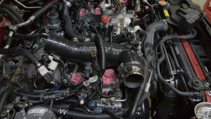
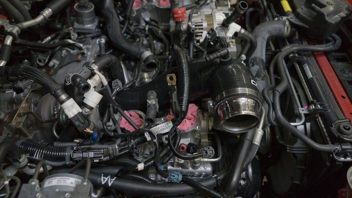
- Remove the OEM turbo inlet hose.
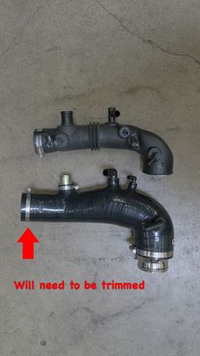
- Line up the COBB silicone inlet hose. Measure it for fit as it is slightly longer to accomodate a variety of turbochargers. You'll likely want to trim it as straight as possible using a razor blade or appropriate hose cutter. It's also suggested to cut it in small increments to avoid making it too short.
- Proceed in the reverse order to re-install your intake manifold and intake system.
- Refill your coolant to the appropriate level and follow the proper purging process to rid of any air in the system.
- We recommend conducting a pressurized smoke test to verify you have no leaks once everything is buttoned up.
- Done!
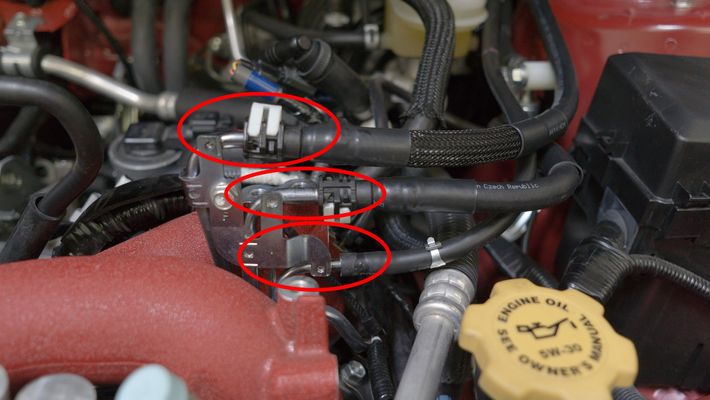
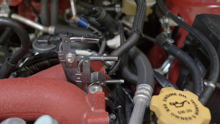
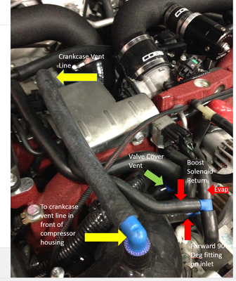
Turbo Inlet Vacuum Hose Placement Quick Reference Guide
STI Turbo Inlet Hose Placement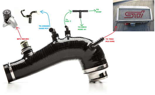
Links
COBB Product Install Instructions for Subaru Vehicles
Main Installation Instruction Repository for Subaru Parts
Calibration Map Notes for Subaru Vehicles
Link to Subaru Map Notes to see what map you should be on given the parts you've added
COBB Customer Support Web Support and Tech Articles: COBB Tuning Customer Support Center Email: support@cobbtuning.com Phone support available 9am to 6pm Monday-Thursday. 9am to 4pm Friday (CST) 866.922.3059 return to www.cobbtuning.comContact Us:
Copyright 2023 © COBB Tuning Products LLC. All Rights Reserved. | www.cobbtuning.com