Cobb Custom Features: GT-R Secondary/Staged Injection and Multi-Fuel Tuning Guide and Information
Intro:
With the introduction of the COBB Staged Injection and Multi-Fuel system, we've added a bunch of features, tables and monitors to allow you to tune the car with an extra 6 injectors that can supply additional fuel through either the stock fuel system, or through a secondary system. We also supply tables that allow you to run a different injector size from your primary set allowing you to achieve stock-like driveability and idle quality, with the fuel delivery available to make big power. The use of a secondary fuel system also allows you to take advantage of the software's ability to deal with multiple fuels and still achieve target air/fuel ratios even when using fuels with significantly different stoichiometric points like methanol.
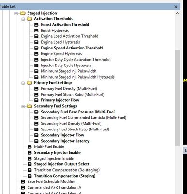
Staged Injection:
Tables:
Setup Tables:
Multi-Fuel Enable
This table will enable the ability to run a second fuel type through your staged injection system. Allowing the use of other fuels like methanol etc. in conjunction with a separate fuel for your primary system. The COBB Multi-Fuel system allows you to apply your own fuel density and stoichiometric ratio to the secondary fuel system to allow the appropriate amount of fuel to be delivered.
Values
A value of 1 in this table will enable the system, while a value of 0 will leave it disabled, allowing the staged injection system to run off of the primary fuel systems settings.
Additional Required Items for Use
A completely separate fuel system for the staged injection system consisting of a fuel cell/tank, pumps, fuel pressure regulator and fuel lines.
Tables activated and used by this system
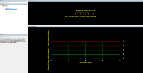
Secondary Injector Enable
This table will enable the ability to run a secondary set of injectors.
Values
A value of 1 in this table will enable the system, while a value of 0 will leave it disabled. When activated it will allow the staged injection system to operate in conjunction with the primary (stock) fuel system to achieve your targeted fueling.
Tables activated and used by this system
- Primary Fuel Density (Multi-Fuel)
- Primary Fuel Stoich. Ratio (Multi-Fuel)
- Boost Activation Threshold
- Boost Hysteresis
- Engine Load Activation Threshold
- Engine Load Activation Hysteresis
- Engine Speed Activation Threshold
- Engine Speed Activation Hysteresis
- Injector Duty Cycle Activation Threshold
- Injector Duty Cycle Hysteresis
- Minimum Staged Inj. Pulsewidth
- Minimum Staged Inj. Pulsewidth Hysteresis
- Primary Fuel Density (Multi-Fuel)
- Primary Fuel Stoich. Ratio (Multi-Fuel)
- Primary Injector Flow
- Secondary Fuel Base Pressure (Multi-Fuel)
- Secondary Fuel Commanded Lambda (Multi-Fuel)
- Secondary Fuel Density (Multi-Fuel)
- Secondary Fuel Stoich Ratio (Multi-Fuel)
- Secondary Injector Flow
- Secondary Injector Latency
- Transition Compensation (Staging)
- Transition Compensation (De-Staging)
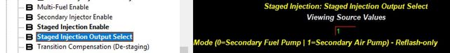
Staged Injection Output Select
This feature has been updated, and selecting the secondary air injection as an output is no longer available. This system will now only be activated through the secondary fuel pump output circuit.
Air injection output has been deprecated and is no longer able to be selected in the software.
This table selects the output for the secondary injection activation. Currently it is only able to go out through the secondary fuel pump circuit.
Activation Thresholds:
Calibration Note
We suggest setting activation and hysteresis values to avoid de-staging while remaining at high engine load. During de-staging fuel is stripped from the manifold walls upstream of the primary injectors, which doesn't occur in a smooth linear fashion. The result temporary fueling may be a concern while at high engine load, but is NOT a concern when the driver releases the throttle after a pull. During lift throttle, fuel cut will stop all injection, and the wall film from all injectors will be consumed uneventfully.
An example of activation settings which might induce the condition we are advising against would be: setting all activations very low, and using Minimum Staged Inj, Pulsewidth as the primary activator, with a small hysteresis. Pulsewidth generally follows the torque curve. If the torque curve tapers as the engine revs out, as many setups do, you may fall below Minimum Staged Inj, Pulsewidth and hysteresis, causing the system to de-stage at high RPM while at WOT.
Regardless of the activation thresholds you choose, using sufficient hysteresis values is another way to avoid destaging during pulls.
Another example of a way to avoid this would be using Injector Duty Cycle Activation Threshold as your primary activator, since duty cycle will continue to increase throughout the powerband. Keep in mind duty cycle will drop during high load gear changes, and set staging activations accordingly.
Boost Activation Threshold
Sets the manifold relative pressure threshold above which the secondary injection system will be allowed to activate.
NOTE: In order to activate the system all activation threshold limits will need to be met.
Boost Hysteresis
When Manifold Relative Pressure drops by this amount, the secondary injection system will be deactivated.
NOTE: In order to activate the system all activation threshold limits will need to be met.
Engine Load Activation Threshold
Sets the minimum engine load (Theoretical Pulsewidth) above which the secondary injection system will be allowed to activate.
NOTE: In order to activate the system all activation threshold limits will need to be met.

Engine Load Activation Hysteresis
Secondary injection will de-activate when theoretical pulsewidth drops by this amount under the "Engine Load Activation Threshold"
NOTE: In order to activate the system all activation threshold limits will need to be met.
Engine Speed Activation Threshold
Sets the minimum engine speed (RPM) above which the secondary injection system will be allowed to activate.
NOTE: In order to activate the system all activation threshold limits will need to be met.

Engine Speed Activation Hysteresis
Secondary injection will de-activate when engine speed drops by this amount under the "Engine Speed Activation Threshold"
Injector Duty Cycle Activation Threshold
Sets the minimum injector duty cycle (%) above which the secondary injection system will be allowed to activate.
NOTE: In order to activate the system all activation threshold limits will need to be met.
Injector Duty Cycle Hysteresis
Secondary injection will de-activate when injector duty cycle drops by this amount under the "Injector Duty Cycle Activation Threshold"

Minimum Staged Inj. Pulsewidth
Sets the minimum staged injection pulsewidth (ms) above which the secondary injection system will be allowed to activate. Use this threshold to ensure the system doesn't activate and run a very small injector pulsewidth. Value is in actual pulsewidth not effective, make sure it is set high enough that the injectors will not go below their minimum pulsewidth or into a non linear region of the primary or secondary injector. Safe values are generally 2-3ms at a minimum but will vary based on your injector choice.
NOTE: In order to activate the system all activation threshold limits will need to be met.
Minimum Staged Inj. Pulsewidth Hysteresis
Secondary injection will de-activate when "staged" injector pulsewidth drops by this amount under the "Minimum Staged Inj. Pulsewidth"
Primary Fuel Settings:
Primary Fuel Density (Multi-Fuel)
When running Multi-Fuel these values are used in the staged injection pulsewidth calcuation in order to account for differences in fuel density when using multiple fuel types. The "Stock" values in these tables represent the fuel density for flex fuel/ethanol varying from 0% ethanol content to 100% ethanol content.
Primary Fuel Stoich. Ratio (Multi-Fuel)
When running Multi-Fuel these values are used in the staged injection pulsewidth calcuation in order to account for differences in the stoichiometric ratio for the fuel being used when using multiple fuel types. The "Stock" values in these tables represent the fuel density for flex fuel/ethanol varying from 0% ethanol content to 100% ethanol content.

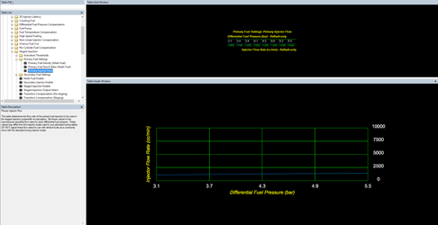
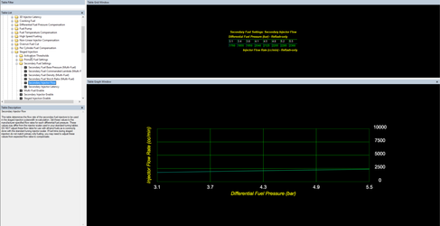
Primary Injector Flow
This table determines the flow rate of the primary fuel injectors to be used in the staged injection pulsewidth re-calculation. Set these values to the manufacturer specified flow rates for each differential fuel pressure. These values may differ from the injector scalar used in your standard tuning tables.
Note: DO NOT adjust these flow rates for use with ethanol fuels as is commonly done with the standard tuning injector scalar.
Secondary Fuel Settings:
Secondary Fuel Base Pressure (Multi-Fuel)
This value specifies the differential fuel pressure (base pressure) of the secondary fuel system and is used as the x-axis lookup value by the "Secondary Injector Flow" table.
Related Tables
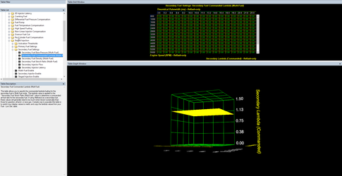
Secondary Fuel Commanded Lambda (Multi-Fuel)
This table allows you to specify the commanded lambda fueling for the secondary fuel in Multi-Fuel mode. This lambda value is applied to the "Secondary Fuel Stoich Ratio (Multi-Fuel)" value to determine a commanded air-fuel ratio for the secondary fuel. If using Methanol as a secondary fuel, these values will generally need to be much richer (lower numerically) than those for gasoline, ethanol, or race gas. A simple way to populate this table is to switch your display values to metric and copy the lambda values from your Fuel - Low Det. table.
Related Tables
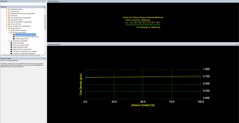
Secondary Fuel Density (Multi-Fuel)
This table is enabled when running Multi-Fuel mode. This value is used in staged injection pulsewidth calculations to account for fuel density differences between the primary and secondary fuels.
Values
Stock values populated in this table are for gasoline other common values you may want are
E85 - 0.782 g/cc
Methanol - 0.792 g/cc
Secondary Fuel Stoich Ratio (Multi-Fuel)
The value in this table is used in staged injection pulsewidth calculations in order to account for the difference in ideal air/fuel ratio (stoich point) between the primary and secondary fuels.
E85 - 9.765:1
Methanol - 6.45:1
Secondary Injector Flow
This table provides the flow rate used in the staged injection pulsewidth re-calculation for the secondary fuel system. Set these values to the manufacturer specified flow rates for each differential fuel pressure. These values may differ from the injector scalar used in your standard tuning tables.
Note: DO NOT adjust these flow rates for use with ethanol fuels as is commonly done with the standard tuning injector scalar. If fuel trims during staged injection do not match primary only fueling, you may need to adjust these values from expected flow rates to compensate.
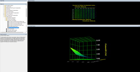
Secondary Injector Latency
This table specifies injector latency across battery voltage and differential fuel pressure for the secondary injectors. This table uses the primary fuel system fuel pressure unless Multi-Fuel is enabled. When Multi-Fuel is enabled, make sure your "Secondary Base Fuel Pressure (Multi-Fuel)" table value is set to the base fuel pressure for your secondary injectors as determined by the regulator when referenced to atmospheric pressure.
Transition Fueling:
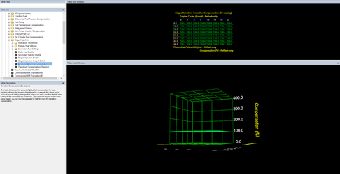
Transition Compensation (Staging)
This table determines the amount of global fuel compensation for each injection following the transition from staged to un-staged, this allows you to account for wall wetting changes that can cause a rich condition directly after turning off the secondary set of injectors. The x-axis is in engine cycles since going staged, you can log this parameter to help fine tune the transition compensation.
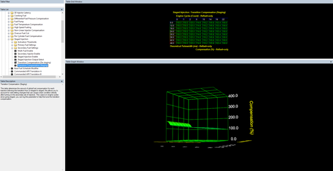
Transition Compensation (De-Staging)
This table determines the amount of global fuel compensation for each injection following the transition from un-staged to staged, this allows you to account for wall wetting changes that can cause a lean condition directly after turning on the secondary set of injectors. The x-axis is in engine cycles since going staged, you can log this parameter to help fine tune the transition compensation.
Monitors:
Fuel Pump (Sub) Status
Units: On (1) or Off (2)
A status flag for the secondary fuel pump where 1 equals active and 0 equals inactive. Helpful for tracking fuel pump transition as well as secondary injection activation when using the secondary fuel pump as the activation signal.
Inj. Duty Cycle
Units: % of time active
Measurement of injector duty cycle in percent of time active..
Inj. Duty Cycle (Staged)
Values: % of time active
Measurement of injector duty cycle for the secondary injection system in percent of time active.
Inj. Pulsewidth 1 Final (Post Compensation)
Units:Milliseconds
Final pulsewidth for the injector on cylinder one after all compensations.
Inj. Pulsewidth Cyl. 1
Units:Milliseconds
Measurement of actual pulsewidth on cylinder one.
Staged Injection Airmass Ratio
Units: %
Percentage of the airmass being combusted by fuel injected by the secondary injectors.
Staged Injection Corrected Lambda
Units: AFR/Lambda
When multi-fuel is enabled this value will represent the final closed loop lambda targeted based on the standard commanded lambda and staged injection secondary commanded lambda.
Staged Injection Cycle Counter
Units: Engine Cycles
Number of engine cycles that have taken place since the staged injection system has activated or deactivated.
Staged Injection Secondaries Active Status
Units: On (1) or Off (2)
A status flag for when the staged injection system is activated where 1 means the system is active and 0 means it is off.
Staged Injection Secondary Injector Latency
Units:Milliseconds
The current secondary injector latency as calculated from the Secondary Injector Latency table.
Staged Injection Secondary Lambda
Units: AFR/Lambda
When multi-fuel is enabled, this represents the commanded lambda used by the secondary injector fueling calculations as looked up in the Secondary Fuel Commanded Lambda (Multi-Fuel) table.
Staged Injection Staged Pulsewidth
Units: Milliseconds
Injector pulsewidth as it would be when secondary injectors are active, this value is calculated whether secondary injection is active or not.
Staged Injection Threshold Flags
Units:
| Value | Description |
|---|---|
| 01 | Engine Speed Threshold |
| 02 | Boost Threshold |
| 04 | Engine Load Threshold |
| 08 | Injector Duty Cycle Threshold |
| 16 | Minimum Staged Inj. Pulsewidth |
| ADD | Multiple Threshold |
Current status of all staged injection activation thresholds, when multiple thresholds have been exceeded their values are added together.
Staged Injection Transition Compensation
Units: %
Fuel compensation currently being applied by the staged injection transition compensation system, this value is pulled from either the Transition Compensation (Staging) or (De-staging) table.
How to Tune:
Mechanical and Electrical Systems Setup:
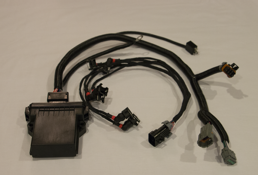
Set up the vehicle with primary and secondary injectors such that all mechanical systems are in place and ready to support 12 injector systems. There are currently two sources for injector driver hardware required for to support auxiliary injectors for GTR.
Visconti Tuning:
https://www.viscontituning.com/products/gtr-12-injector-conversion
Linney Tuning
http://www.linneytuning.com/product/asnu-12-injector-kit/
In order to install the 6 additional injectors you will need to do one of the following
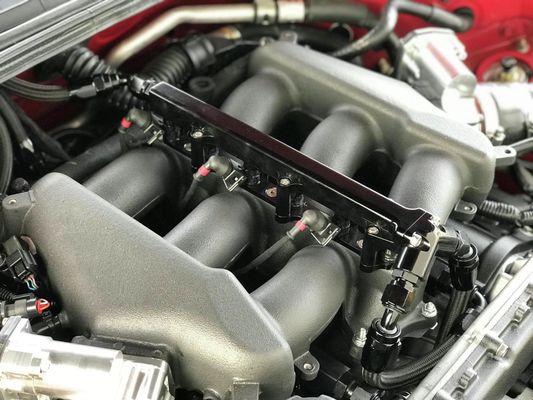
- Run an aftermarket 12 injector manifold such as Boost Logic OR AMS (these are expensive but support higher airflow for extremely high HP applications)
- Run a converted stock manifold with a 3rd fuel rail added that is purchased on a core return basis or done at a machine shop.
Accesstuner Calibration:
Tune with the Primary injectors only at first
Tuning process 1 (starting a brand new 12 injector tune):
- first tune the car on 6 injectors as normal.
- set up the fuel injectors in using "injector scalar" and "injector scalar flex fuel" as you normally would for a standard or a flex fuel tune.
- Tune the car using low ethanol and low boost so that fuel demand is low and can be satisfied by the primary injectors.
Example Files
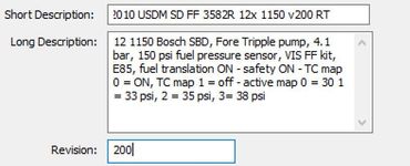
Map: 4900 2010 USDM SD FF 3582R 12x 1150 v100 RT.ptm
Datalog: v100 - running on 6 injectors.csv
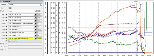
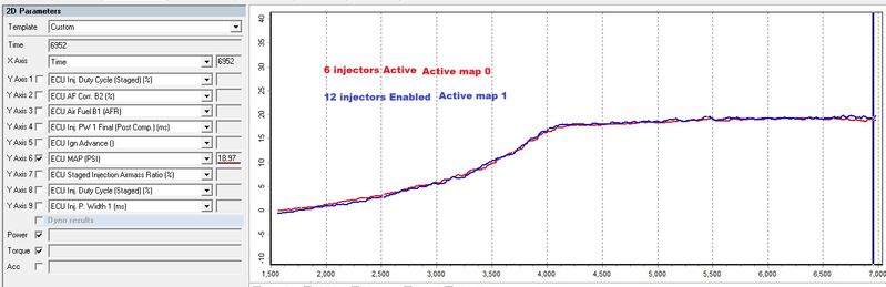
This data log shows this larger turbo car running E80 at wastegate boost. The car has great fuel trims and is otherwise completely tuned to run on 6 injectors using this calibration. However you can see here that the car is completely out of fuel running just one set of 1150cc injectors. Noted in the log you can see that the Injector Duty Cycle is 107%.
Double Check VE Table
The GTR is effectively tuned at this point as the VE table and other parameters are well matched for the vehicle but we cannot run more boost since the car is out of fuel. This is where the second set of injectors come in.
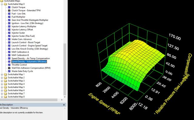
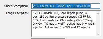
12- Injector setup
The screen shot to the right shows the highlighted table differences between the functional 12 injector file and the 6 injector calibration file. You'll now want to enable the secondary injection system using the Secondary Injector Enable
The first thing to set up is the Stage injection Activation Thresholds. In order to activate the secondary injectors ALL conditions in the activation thresholds must be met. For this calibration there are just 4 parameters that are raised minimally and therefore must be met in order to activate the secondary injectors.
This map is set up so that they will activate when.
- Boost - boost in this calibration must be above 5 psi
- Engine speed - engine speed must be above 2500 RPM
- Injector duty cycle - IDC must be above 25%
- Minimum staged pulse width. The minimum pulsewidth used once the secondary injectors are active must be at least 2 msec
Enable and Set up staged Injection Activation Triggers
Next we'll use the table Staged Injection Output Select to choose what source the ECU will use in order to enable the auxiliary injector driver. This example calibration uses the secondary air pump activation relay as the output to activate the auxiliary driver hardware.
Primary Injector Fuel Settings: Primary injector Flow and Latency
Next you'll want to set up the Primary Injector Flow and Secondary Injector Flow as a function of Fuel Pressure as well as the Secondary Injector Latency. While some injector data is available on our website here: GT-R Injector Data You may need to reach out to your manufacturer for data if your injectors are not covered.
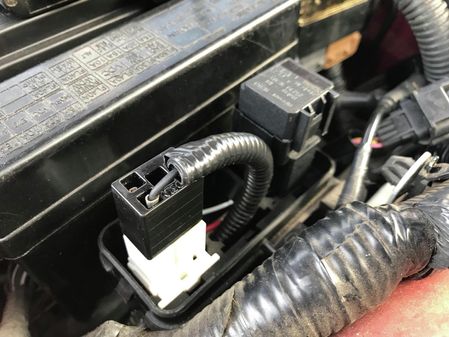
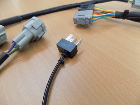
The Injector Driver hardware utilize a Plug and Play electrical connector to plug into the Air pump relay, or an extended wire so you can tie in to the secondary pump activation somewhere on the harness (commonly done near or at the pump)
Example Files
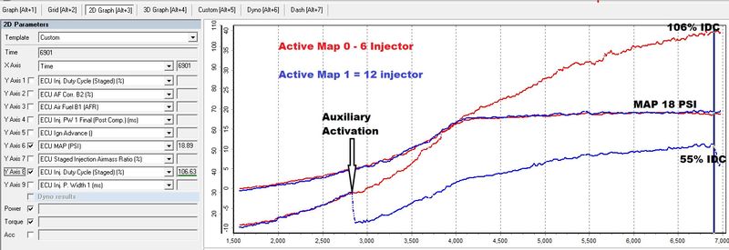
Running 12 Injectors
Tuning the Activation
Compare Injector Duty Cycle between the two options. With the same boost levels using the map 0 option (6 injectors - red) and active map 1 (12 injectors - blue). Of special note is that when using the 6 injector system Injector Duty Cycle (IDC) is 106%. This is slightly beyond the limit of 6 injectors with the current setup and running E80. When the same car is run on 12 injectors the IDC drops to ~55% (Blue). At this point you can now run more boost than previously since your injectors aren't needing to work as hard to accomplish the same power level as when utilizing only the primary fuel system.
Auxiliary Injection Activation linked to thresholds
Activation of auxiliary injection is linked to "activation thresholds". All activation thresholds must be met. On this calibration a boost pressure of 5 PSI and achieving an IDC of 25% on the primary (non-staged) fuel system of 25% are the limiting factors. Once these two thresholds are met, the total Injector open time is split between the primary and secondary injectors. You can see the IDC (green) immediately reduce to account for activating a second set of 6 injectors.
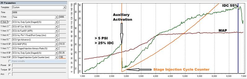
Total Injector open time decreases when auxiliary injectors are activated
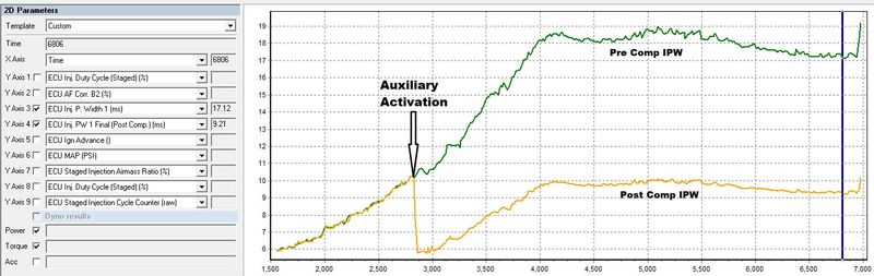
The total Injector open time (shown in yellow) decreases in proportion to the total injector flow after auxiliary injection is activation. The total injector pulse width prior to this compensation is calculating the required pulsewidth if only the 6 primary injectors are used.
Typically activating the auxiliary injection system is going to create a transitional lean condition. This is mostly due to the fact that the secondary injectors are located further away from the combustion chamber than the primary set. As a result, upon activation some of the fuel is delayed in reaching the cylinder, and in wetting the walls of the manifold. This fuel loss is seen as the lean transient shown on the graph in the circled area. You're able to solve this issue by using the Transition Compensation (Staging) table.
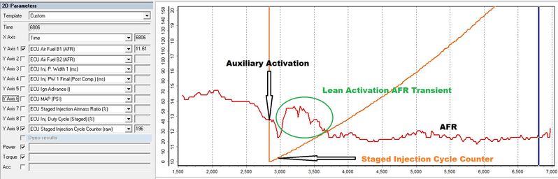
In order to add additional fuel to account for the loss at the time of activation, we use the Transition Compensation (Staging) table. This table is a function of load and a count of engine cycle's after the activation of the staged injection system. Staged Injection Cycle Counter. Adding fuel here allows us to smooth out the lean areas.
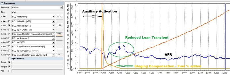
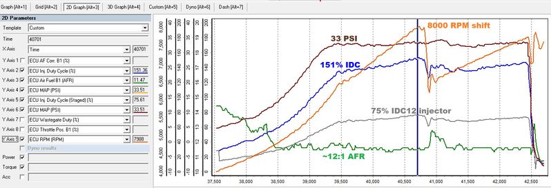
The car in these examples is making around 1250 HP at 33PSI of manifold pressure (seen in brown) and is only using 75% of it's total available fuel flow from the 12 injectors (shown by the Inj. Duty Cycle (Staged) % in gray). If we were running just the primary injectors you would be seeing an impossible injector duty cycle of 151% (blue).
Copyright 2023 © COBB Tuning Products LLC. All Rights Reserved. | www.cobbtuning.com