
SUBFMIC002BK and SUBFMIC002SL – COBB Subaru VA WRX Front Mount Intercooler Kit
VA WRX 2015 - 2020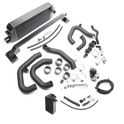
Congratulations on your purchase of the COBB Tuning VA WRX Front Mount Intercooler Kit! The following instructions will assist you through the installation process. Please read them BEFORE beginning the install to familiarize yourself with the steps and tools needed. If you feel you cannot properly perform this installation, we HIGHLY recommend you take the vehicle to a qualified and experienced automotive technician.
IMPORTANT! Installing this kit will require custom tuning or utilizing an appropriate Stage Power Package map if you have a matching mechanical configuration. Please consult with COBB or an authorized ProTuner in your area.
Parts List
- Hot Side Intercooler Piping
- (1) Upper intercooler pipe
(1) Lower intercooler pipe
(1) 2" - 2.5" silicone reducer
(1) 3" - 2.5" silicone reducer
(1) BPV recirculation 1” silicone coupler
(1) BPV to hot pipe 35mm silicone coupler
(2) #44 clamps
(1) #36 clamp
(2) #24 clamps
(2) #16 clamps
(1) #48 clamp
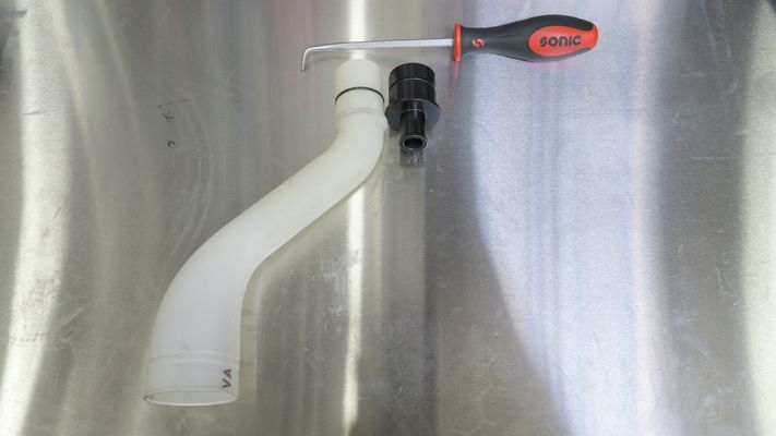
(1) 1” plastic elbow
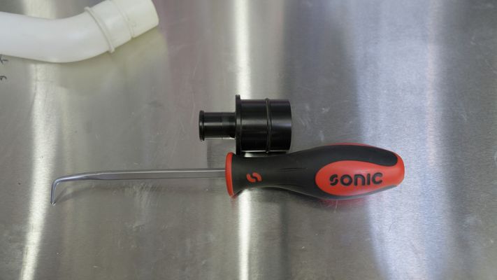
(1) crankcase vent hose adapter
(2) feet 0.5” diameter silicone hose
(4) feet 6mm vacuum hose
- (1) Upper intercooler pipe
- Cold Side Intercooler Piping
- (1) Upper intercooler pipe
(1) Middle intercooler pipe
(1) Lower intercooler pipe
(1) 2.75” - 2.5” silicone reducer
(2) 2.5” silicone coupler
(1) 3” - 2.5” silicone reducer
(2) #48 clamps
(6) #44 clamps
(1) Aluminium insert
(1) Rubber isolator
(1) M8x25 bolt
- (1) Upper intercooler pipe
- FMIC core
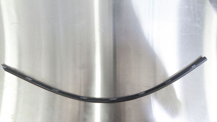
- Bumper beam
- Washer fluid reservoir silicone
- Washer fluid reservoir cap
- Washer fluid reservoir bracket
- 6mm flanged head bolt
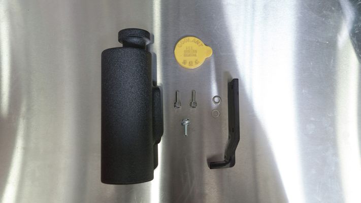
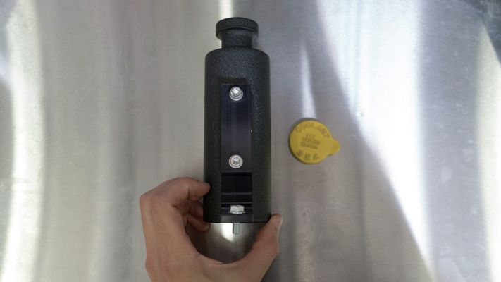
- Coolant reservoir
- (2) 6mm socket head cap screws with washer
- (1) flange head bolt
Tools Needed
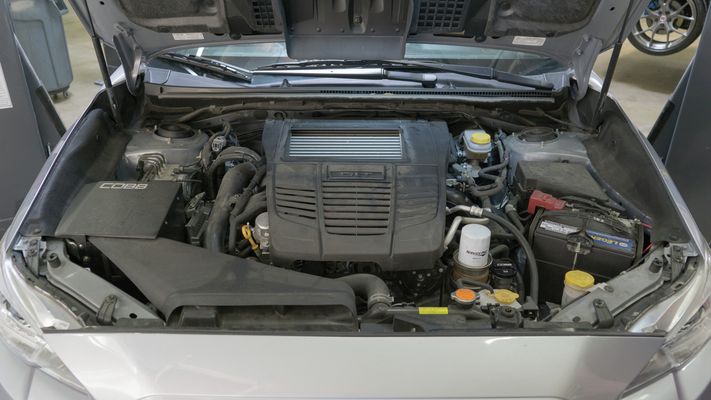
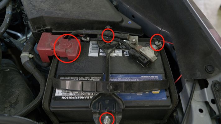
Removal of Intake
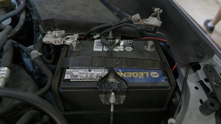
- Remove the battery cables, tie down, and battery using a 10mm socket.

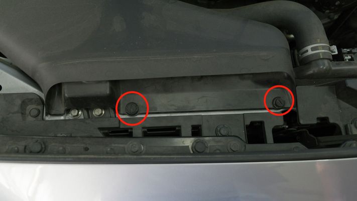
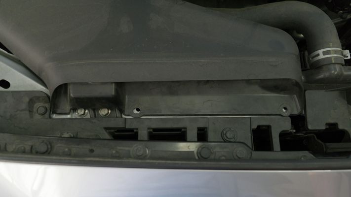
- Remove the OEM snorkel by popping out (2) flathead push-clips
- NOTE: The COBB FMIC is designed to work with the COBB SF Intake. We cannot guarantee fitment with other manufacturer's intake systems.

- NOTE: The COBB FMIC is designed to work with the COBB SF Intake. We cannot guarantee fitment with other manufacturer's intake systems.
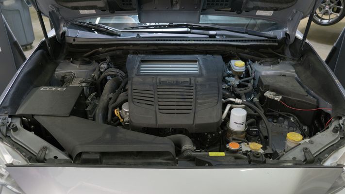
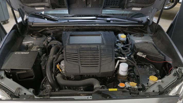
- Remove the plastic engine cover by popping out (2) flathead push-clips. Once the push-clips have been removed, you'll want to lift straight up from the underside of the engine cover.
Removal of Bumper
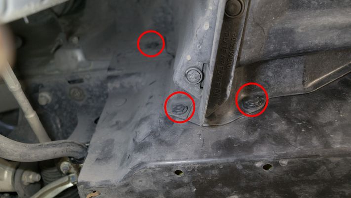
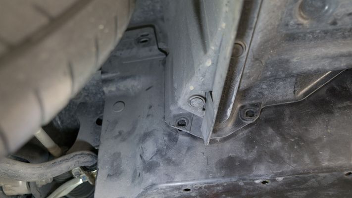
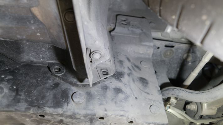
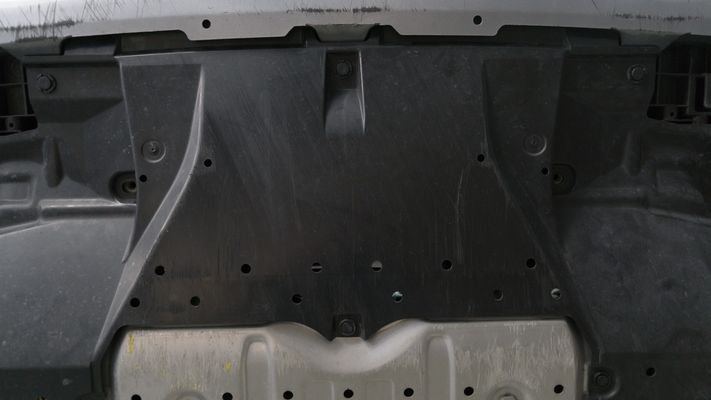
- Remove the undertray
- Release the (3) flathead push-clips from the passenger wheel well.
- Release the (3) flathead push-clips from the driver wheel well.
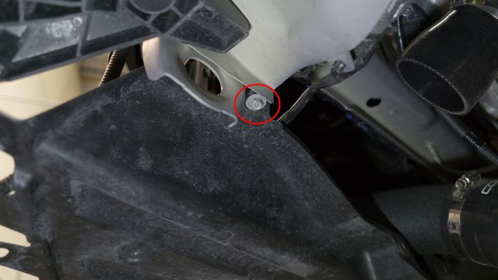
- Remove (2) 12mm bolts.
- Remove (7) plastic push type retainers.
- Remove the lower wheel well tray by unscrewing (1) Phillips head screw on the driver side.
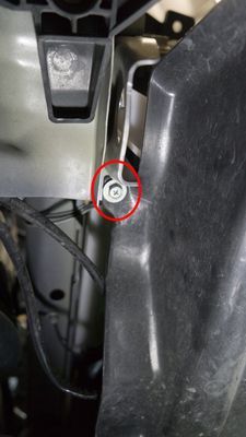
- Remove the lower wheel well tray by unscrewing (1) Phillips head screw on the passenger side.
- Release the (3) flathead push-clips from the passenger wheel well.
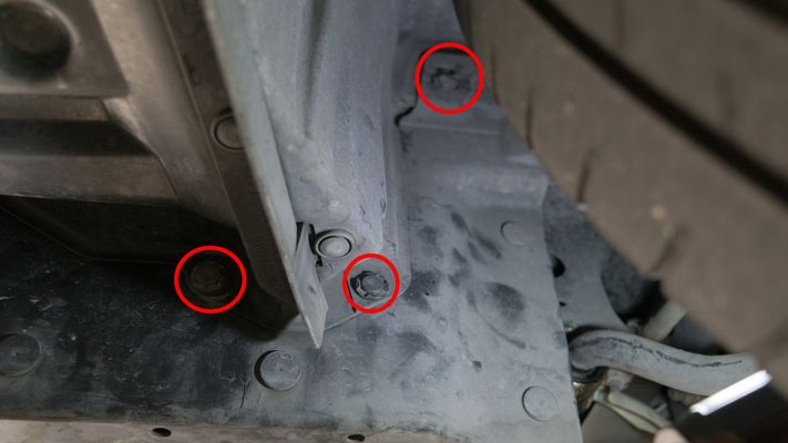
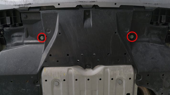
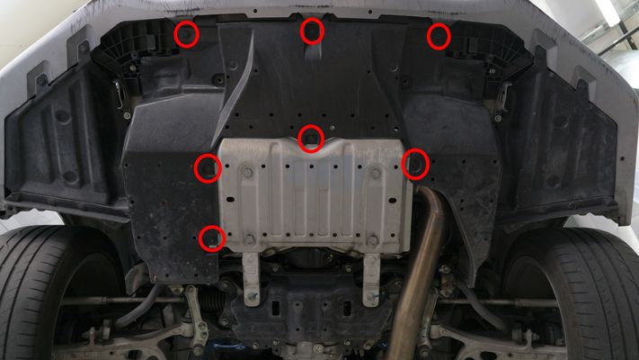
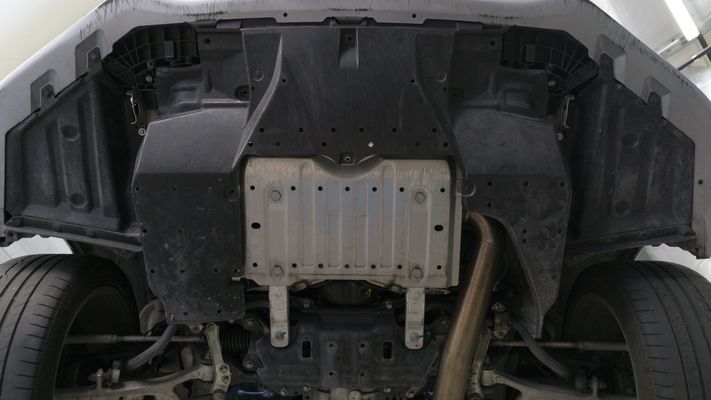
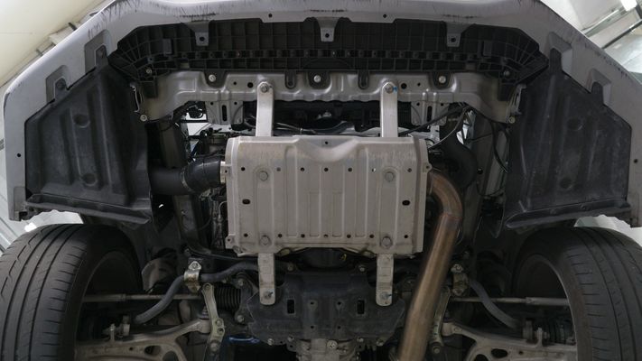
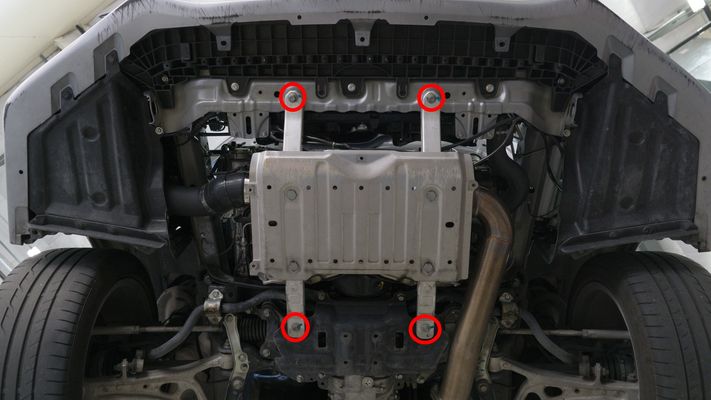
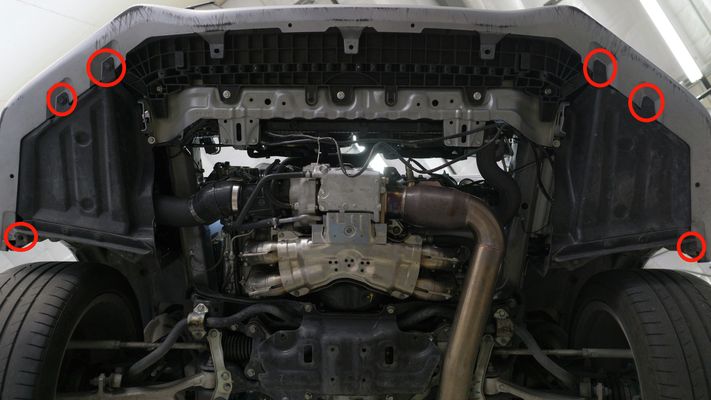
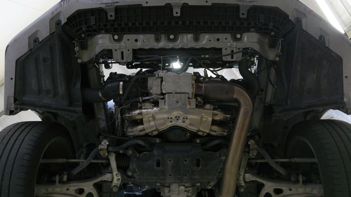
- Remove the skid plate by unbolting (4) 12mm bolts.
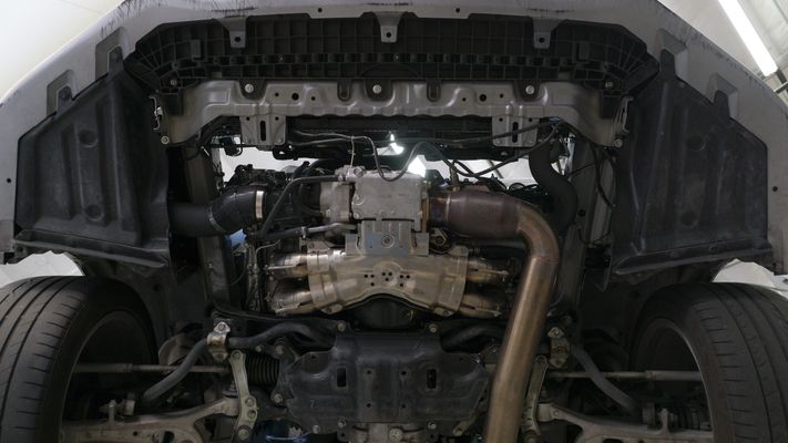
- Remove the front bumper.
- On the bottom of the bumper, remove the (6) push clips.
- Release (1) push clip from the drivers side wheel well.
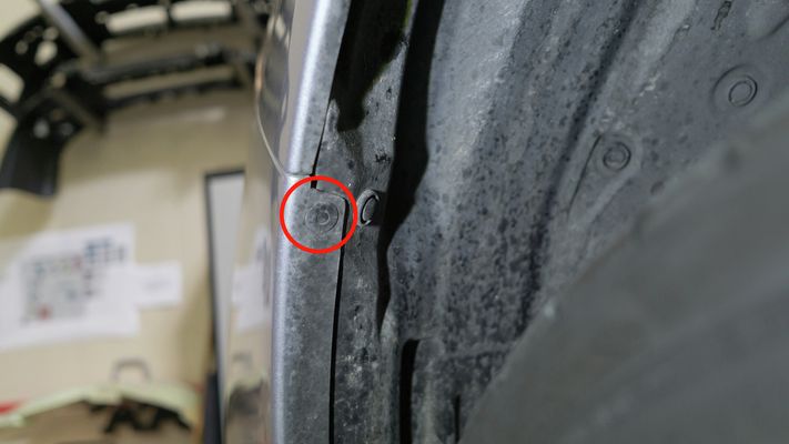
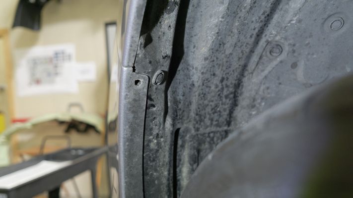
- Release (1) push clip from the passenger side wheel well.
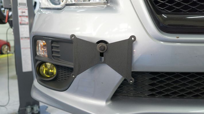
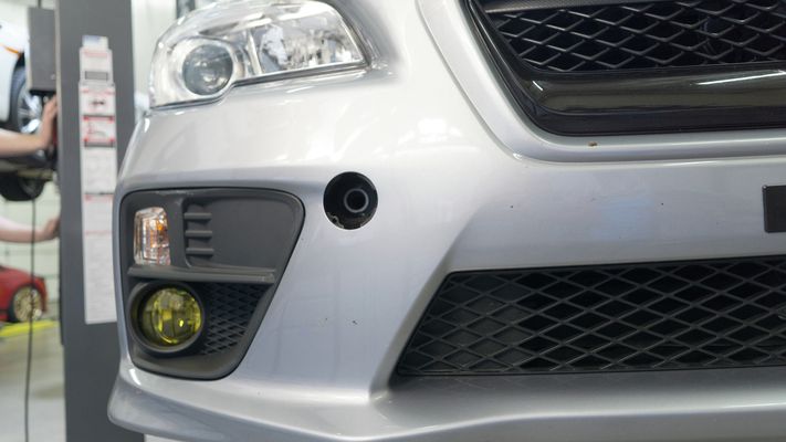
- If you have a front license plate relocation bracket installed to your front bumper, you will need to remove it at this point.
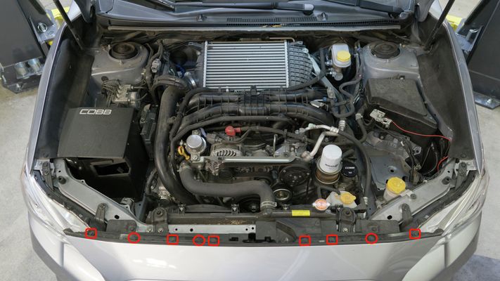
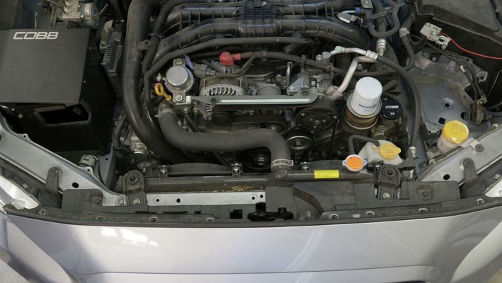
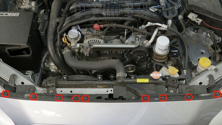
- On the top of the bumper, remove (3) push pins and (6) 10mm bolts
- Remove the black trim/weatherstripping.
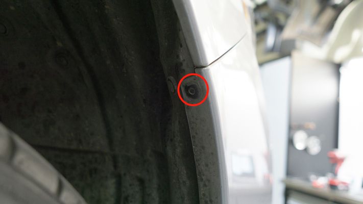
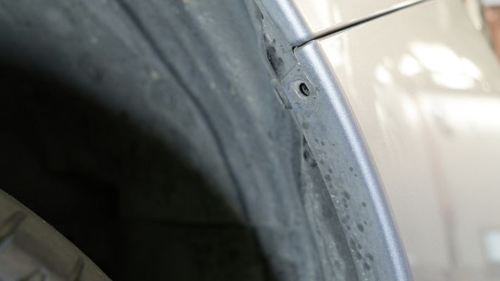
- Release the bumper pressure clips on the passenger side wheel arch by applying a small amount of outward pressure.
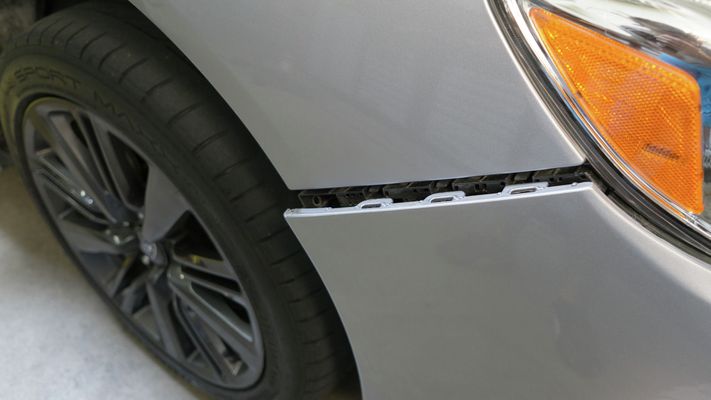
- Release the bumper pressure clips on the driver side wheel arch by applying a small amount of outward pressure.
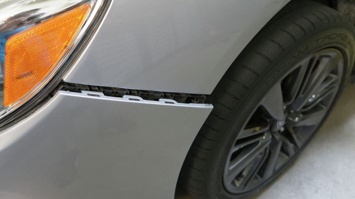
- Gently pull the bumper away from the car.
- NOTE: It helps to have (2) people to hold the bumper, but isn't necessary.
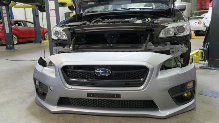
- NOTE: It helps to have (2) people to hold the bumper, but isn't necessary.
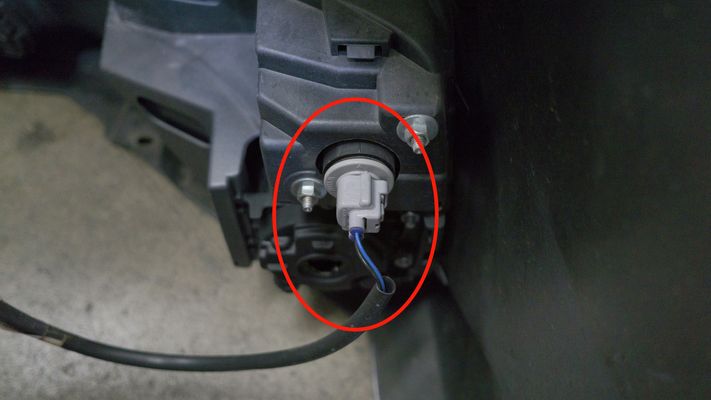
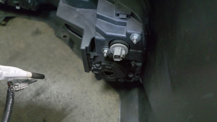
- As you remove the bumper, be wary of the foglight connectors. You should have enough length in the harness to gently set the bumper down while you disconnect the harness.
- Remove the foam insert.

- --- THIS STEP ONLY APPLIES TO THE 18 WRX —
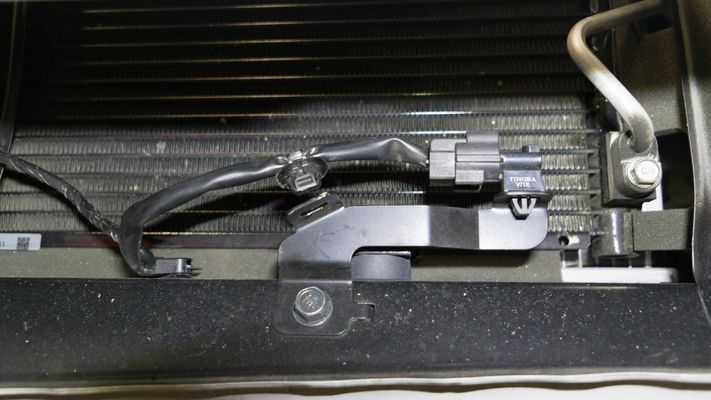
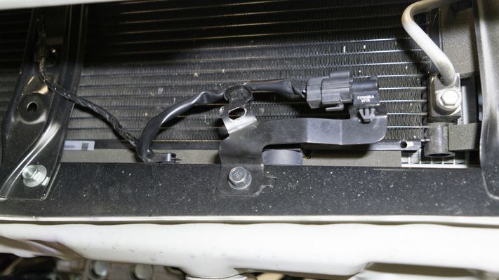
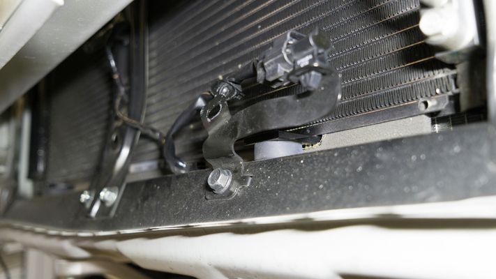
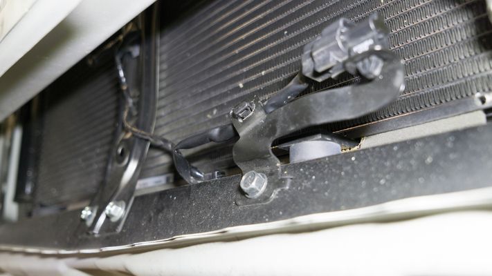
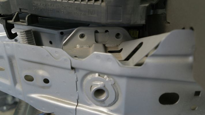
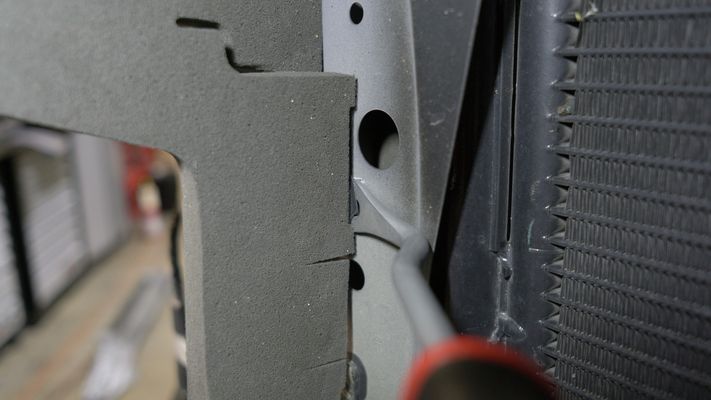
- Prior to installing the intercooler core, you will need to bend the ambient air temperature sensor bracket to allow clearance for the intercooler core. If you do not bend the bracket, you will need to trim the bumper accordingly.
- Prior to installing the intercooler core, you will need to bend the ambient air temperature sensor bracket to allow clearance for the intercooler core. If you do not bend the bracket, you will need to trim the bumper accordingly.
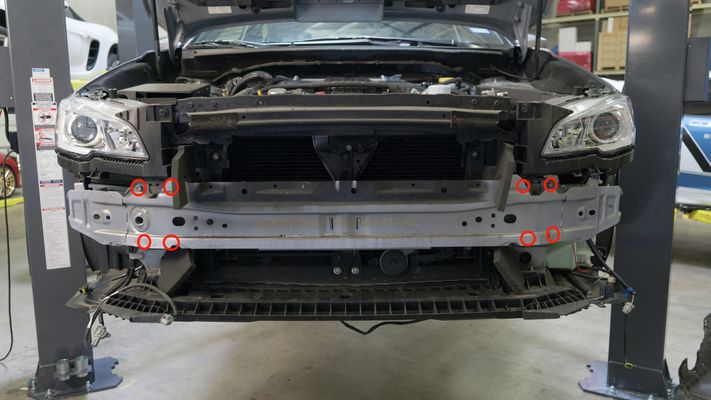
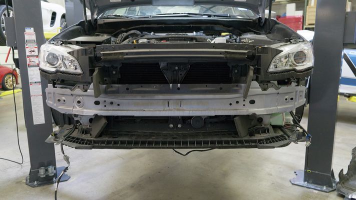
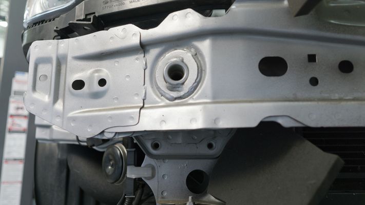
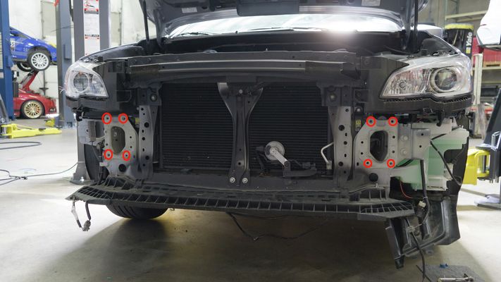
- Remove the bumper beam by unbolting (8) 12mm bolts. There will be (4) on each side.
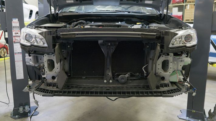
- Remove the foam insert by using a retainer clip remover tool.
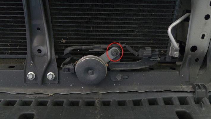
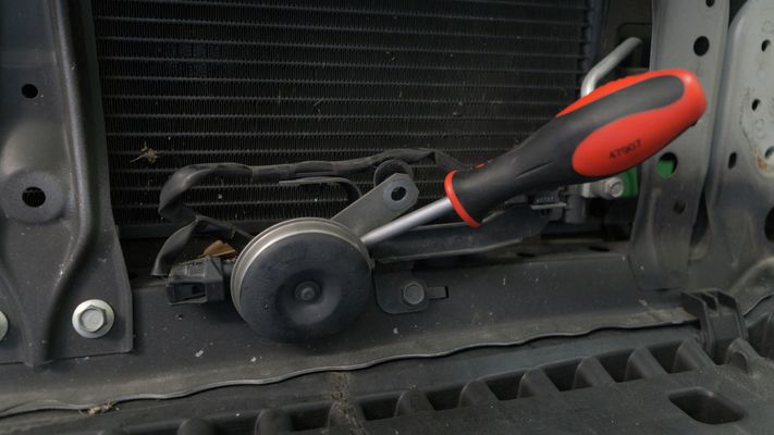
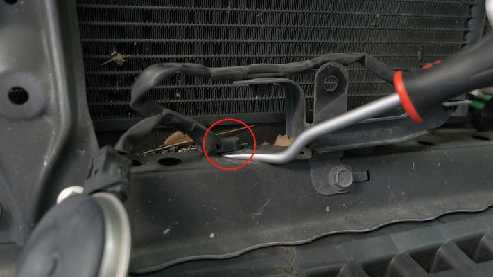
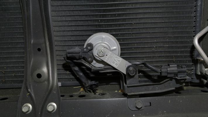
- Flip the horn orientation as depicted. You will need unbolt (1) 12mm bolt and release the retainer clip. Once released, you will flip the horn around and when bolted back up, the bolt will be facing the engine bay.
- On the bottom of the bumper, remove the (6) push clips.
Removal of TMIC
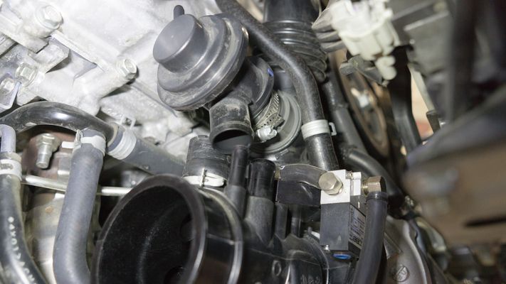
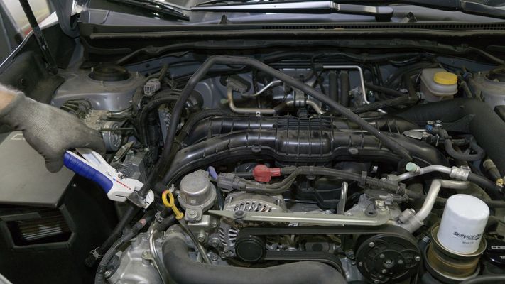
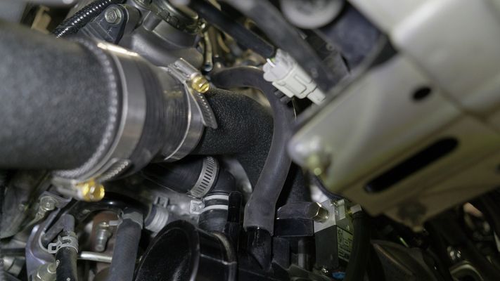
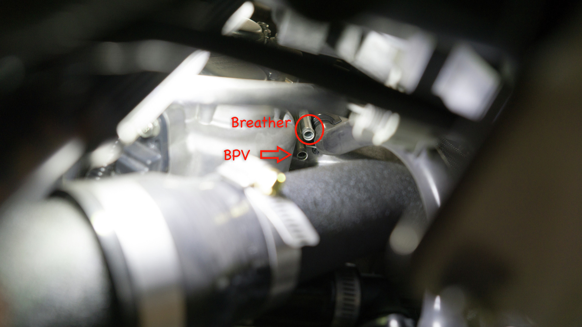
- Under the car, remove (2) breather lines from the intake tube.
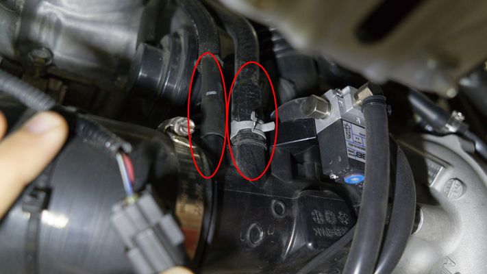
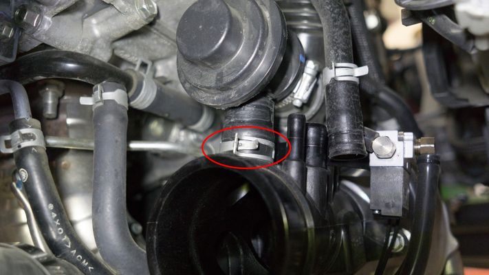
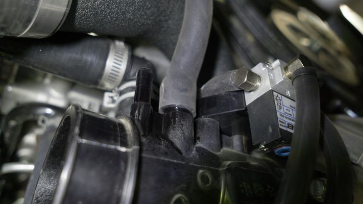
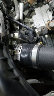
- Loosen the intake silicone clamp to allow access to the BPV.
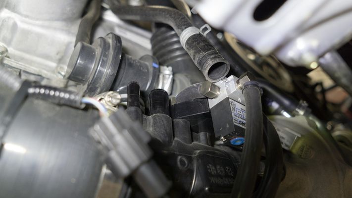
- Loosen the BPV to factory turbo inlet clamp.
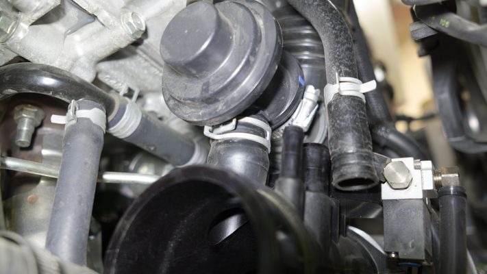
- Remove the vacuum hose to the BPV.
- Loosen the BPV to factory hot pipe clamp.
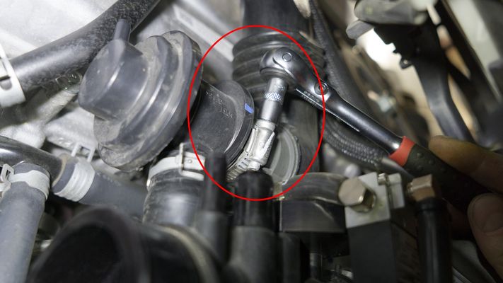
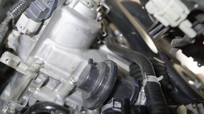
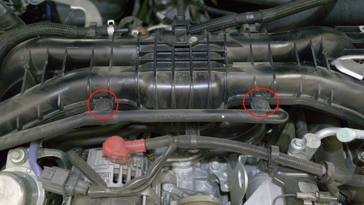
- Remove (2) 12mm bolts on the factory hot pipe to turbo. You will need a 6" extension for one of the bolts.
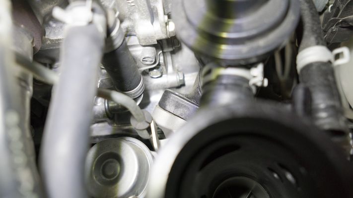
- Applying a small amount of pressure, remove the BPV from the turbo inlet.
- Pull the BPV away from the factory hot pipe.
- Loosen the clamp from the intercooler to hot pipe.
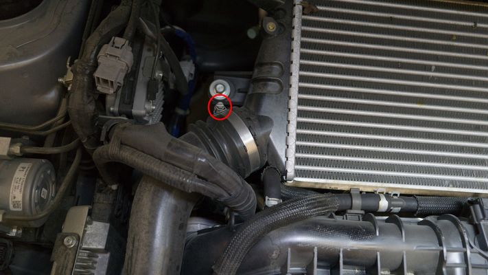

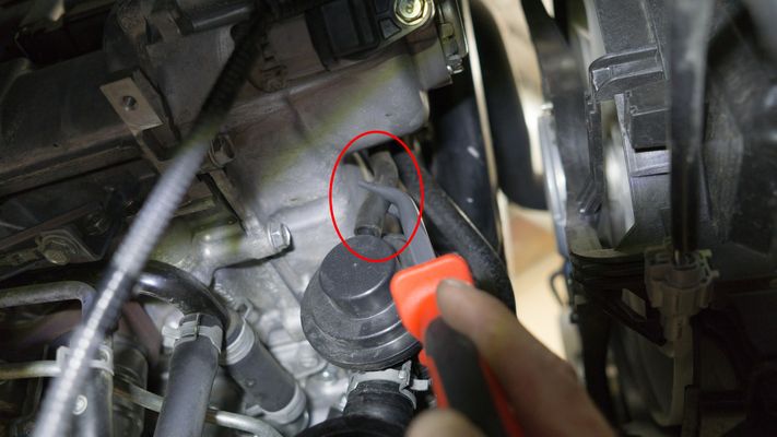
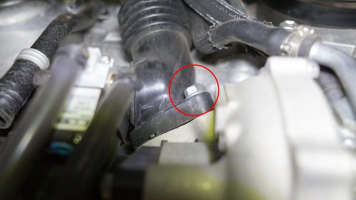
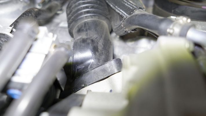
- Remove the hot side pipe. Be cautious of the retainer clip near the intake manifold.
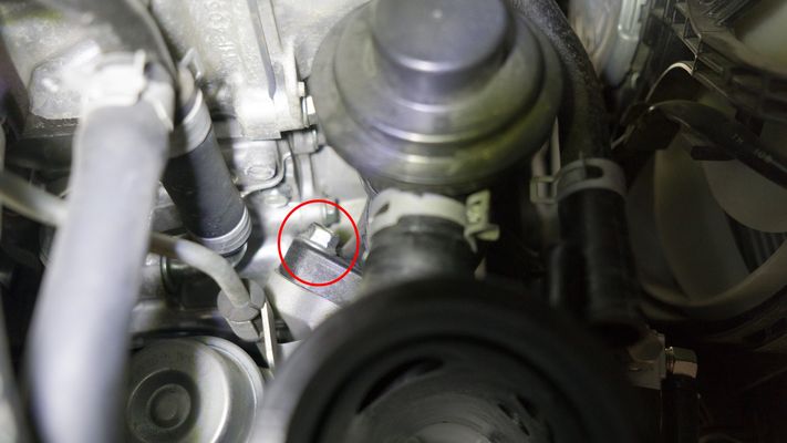
- Loosen the 8mm clamp on the right hand side of the intercooler.
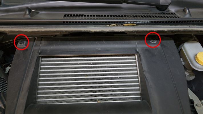
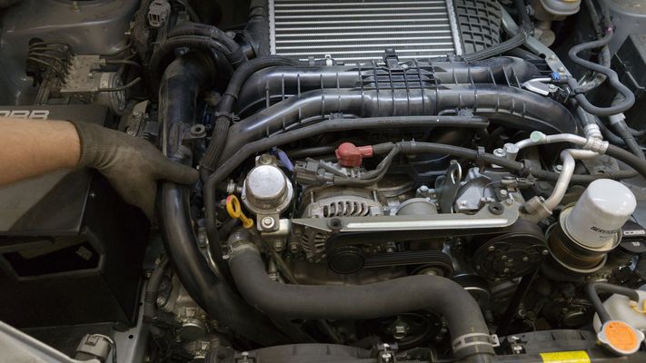
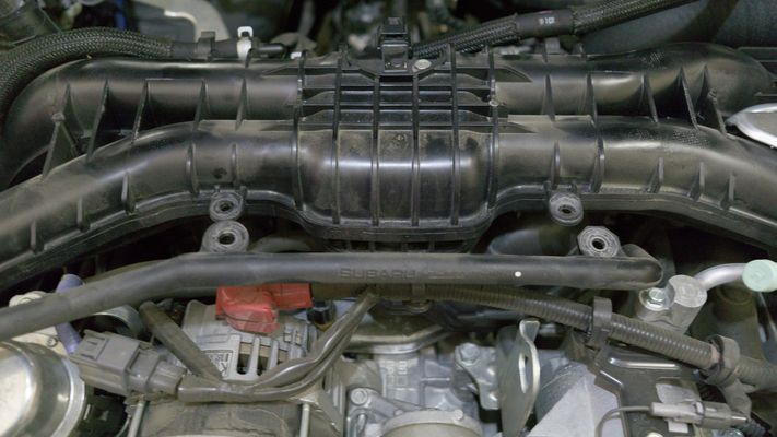
- Remove (4) 12mm bolts holding the intercooler down.
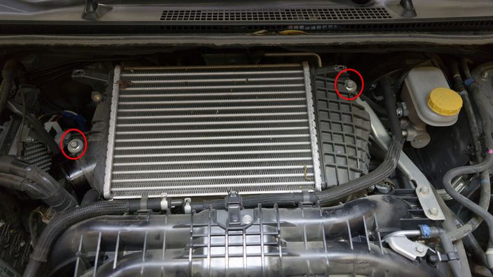
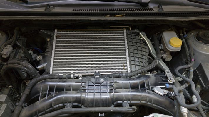
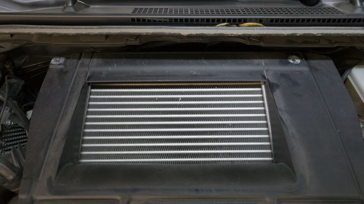
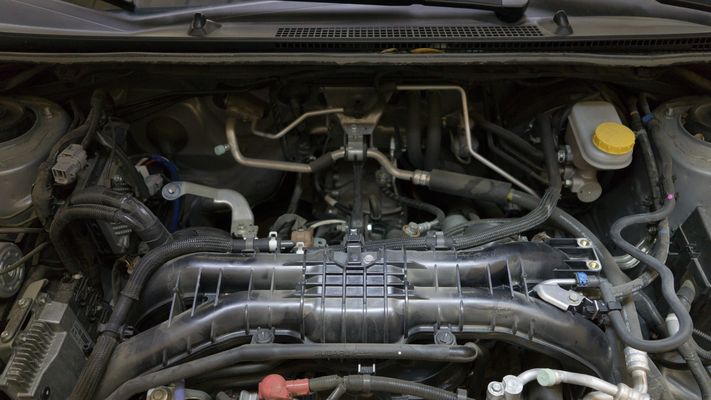
- The TMIC should easily lift away from the motor.
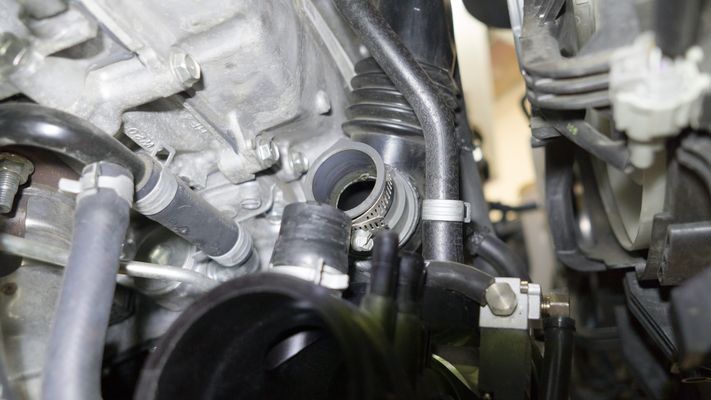
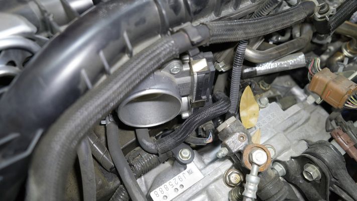
- Loosen the 8mm clamp on the throttle body coupler and remove the coupler..
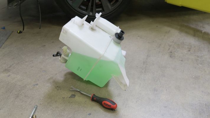
Removal of Washer Fluid Reservoir
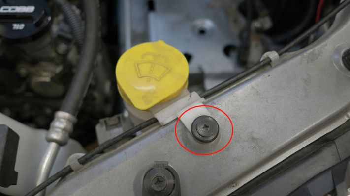
- On the top of the engine bay, near the washer fluid reservoir, remove (1) Phillips head screw.
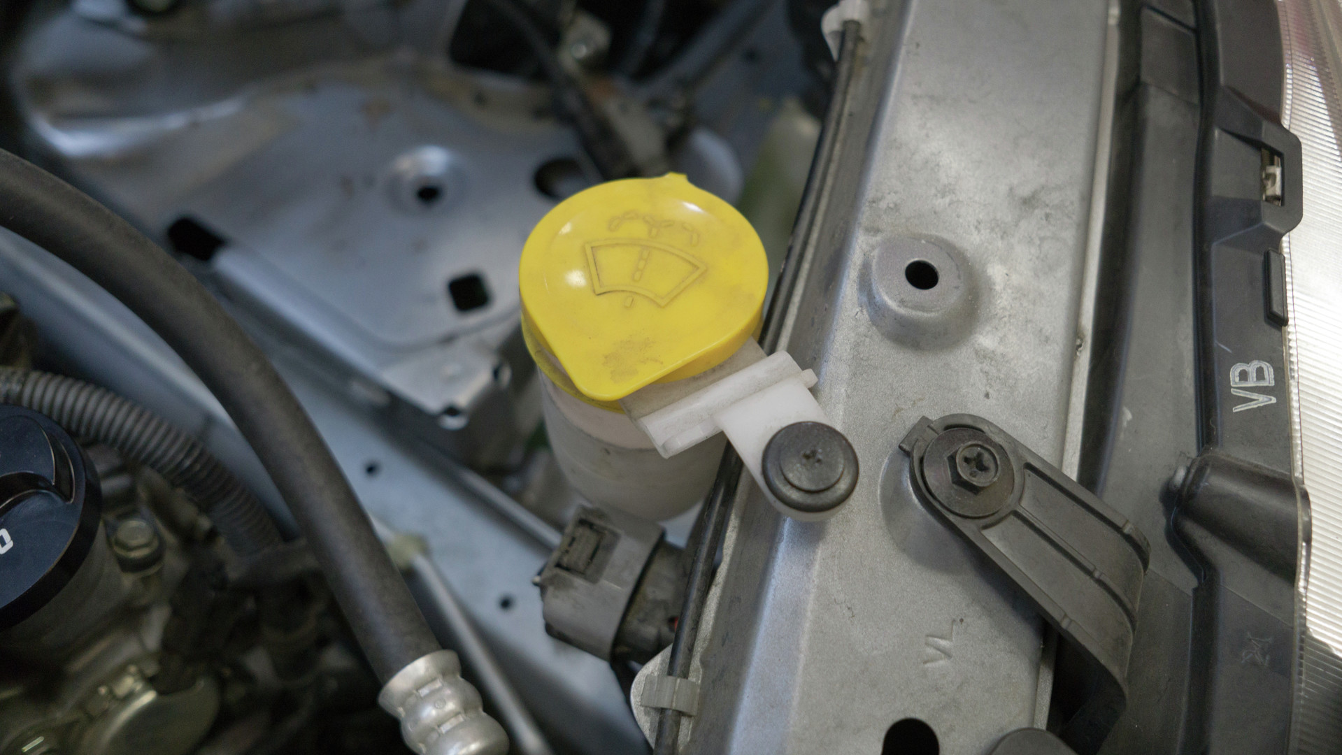
- Twist and remove the reservoir spout head.
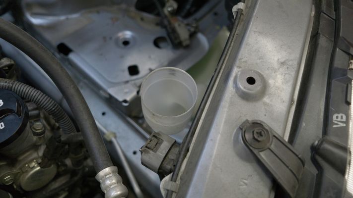
- Twist and remove the spout funnel.
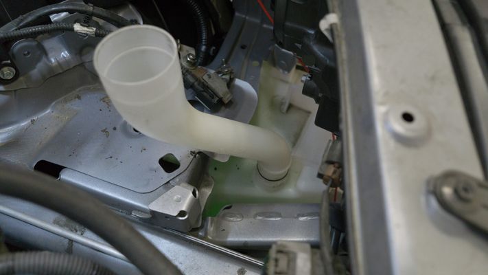
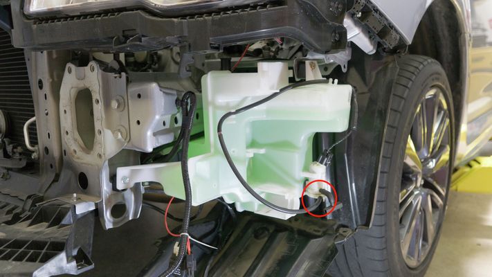
- From the side of the washer fluid reservoir, remove the vacuum hoses running to the windscreen washers.
- As soon as you remove the vacuum hose, fluid will start to drain. You'll want to plug the hole with either a 3/16" vacuum cap or similar.
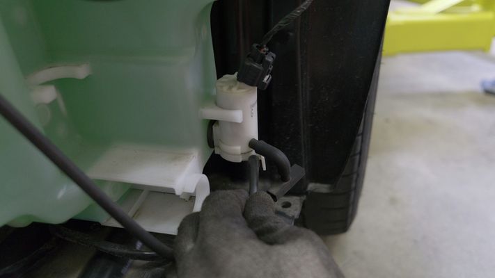
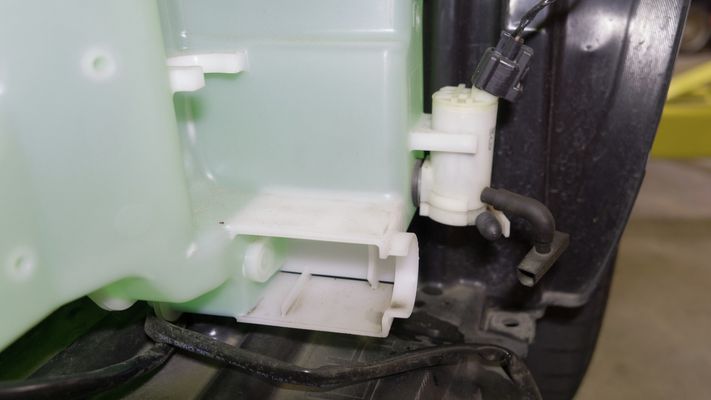
- As soon as you remove the vacuum hose, fluid will start to drain. You'll want to plug the hole with either a 3/16" vacuum cap or similar.
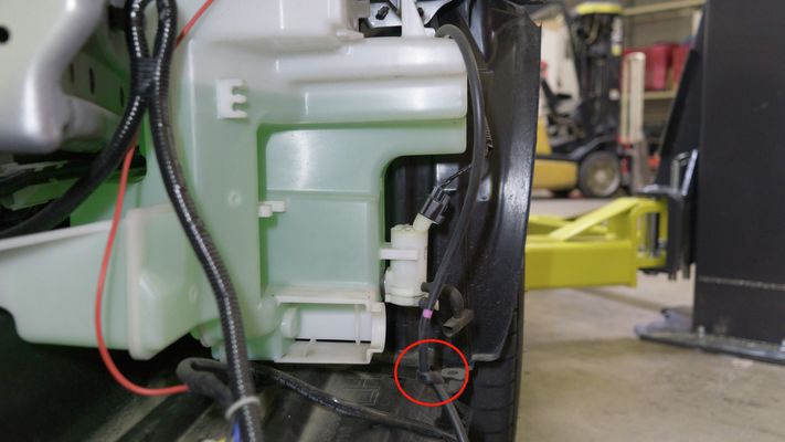
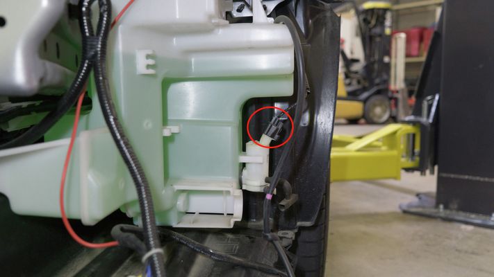
- Tie off or plug the windscreen washer vacuum hose.
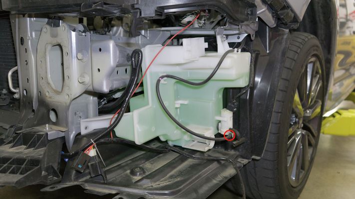
- Remove the electrical harness for the fluid washer.
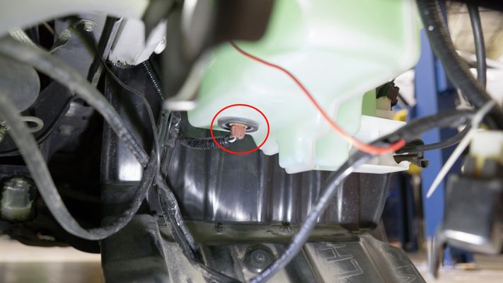
- Remove the washer fluid level sensor.
- Remove the electrical harness clip holding it to the reservoir.
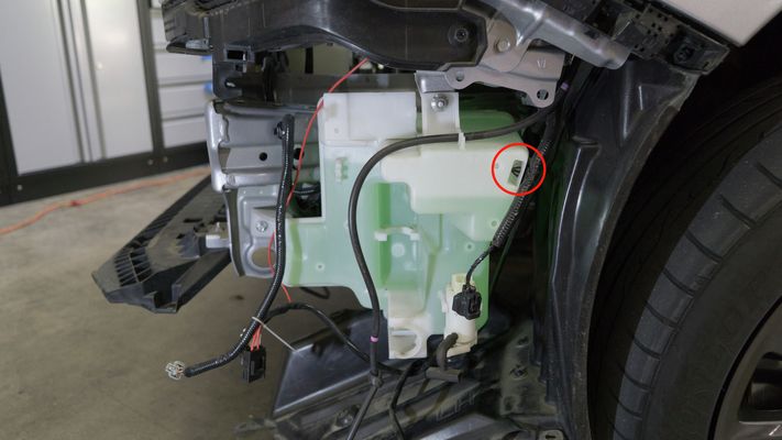
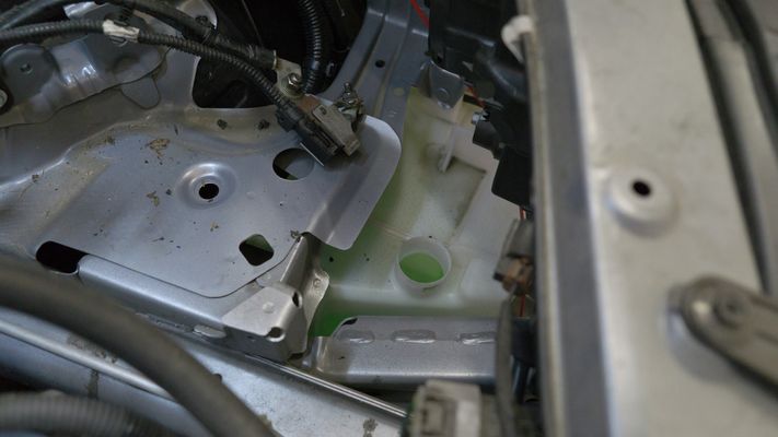
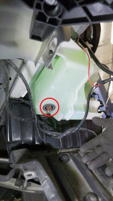
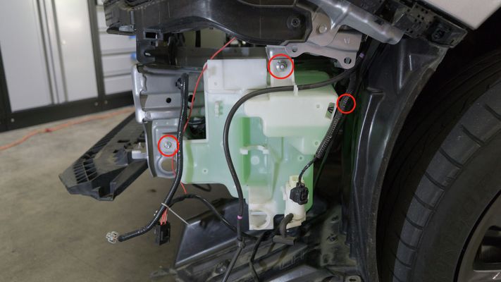
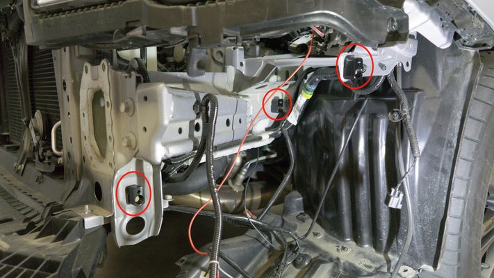
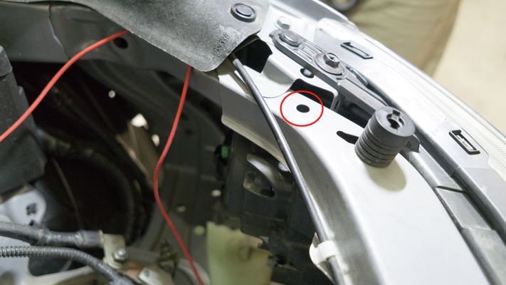
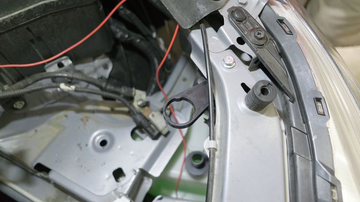
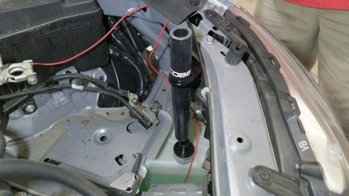
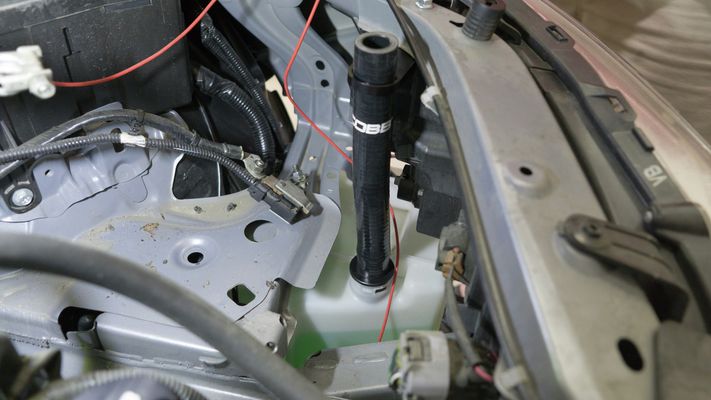
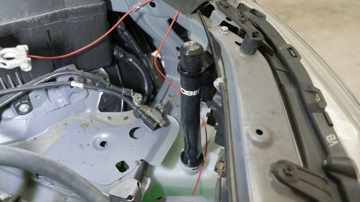
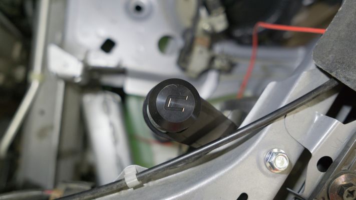
- Using a 12" extension, remove (3) 10mm bolts holding the reservoir to the chassis.
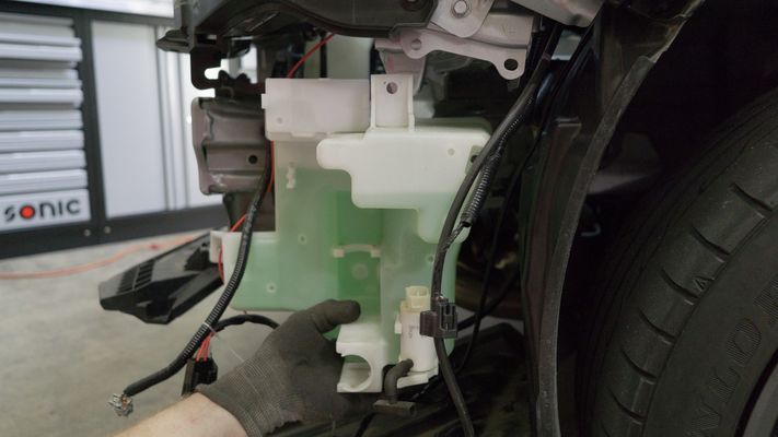
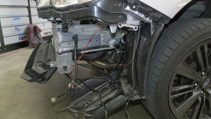
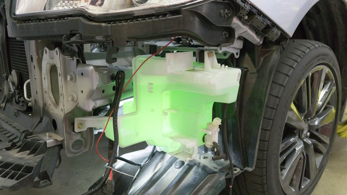
- Remove the washer fluid reservoir.
- Remove the o-ring from the previous spout and place it on the new washer fill hose tank adapter.
- Install the (3) provided spacers using the provided (2) M6x20mm flange head bolts and (1) M6x20mm flange head nut. Make certain to orient the spacer vertical with the empty thread slot on the top side.
- Install the washer fluid reservoir onto the spacers using the provided (2) 10mm bolts and (1) 10mm nut.
- Clip the washer fluid level sensor back in.
- Connect the washer fluid line back to the tank.
- Clip the washer fluid motor harness back in.

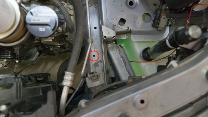
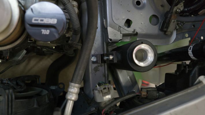
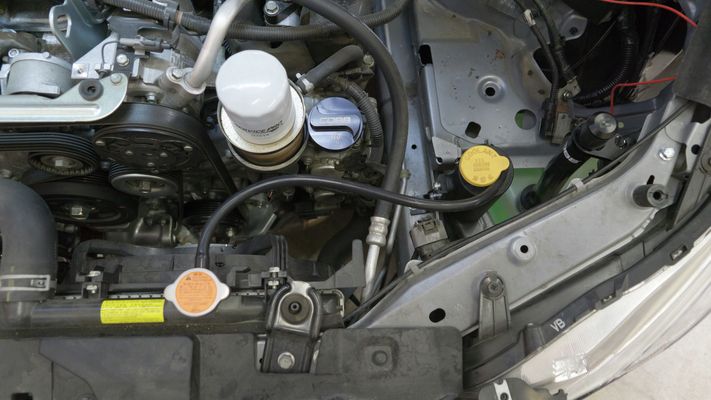
- Install washer fill bracket using the provided (1) 6mm flange head bolt.

- Slide the washer fill hose in until it meets the washer fluid inlet.
- Install washer fill hose on reservoir spout adapter.
- Top off reservoir with fluid.
- Install COBB washer fluid reservoir cap.
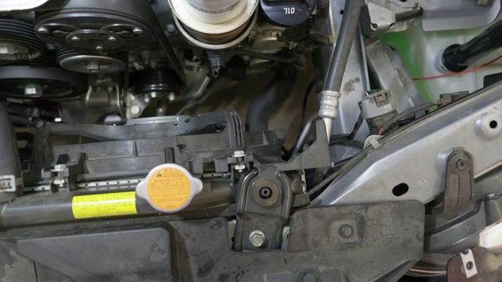
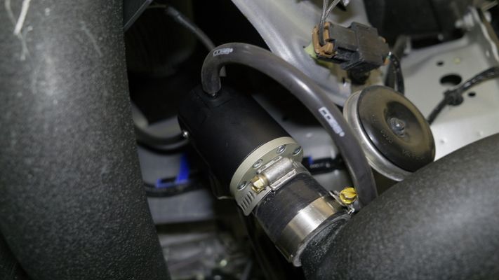
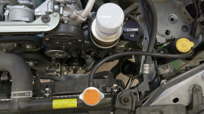
Remove Coolant Reservoir
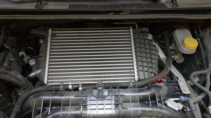
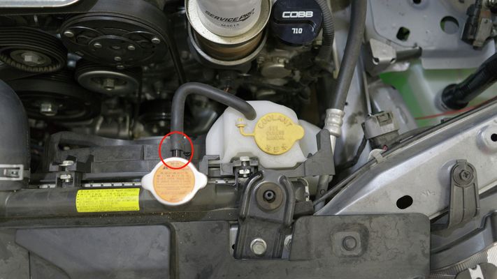
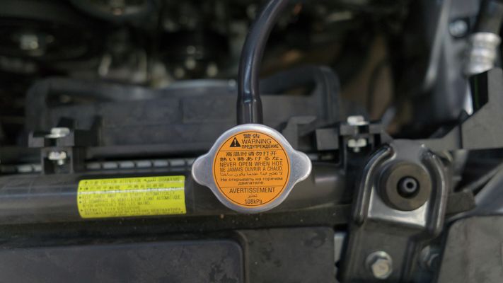
- Remove vacuum hose from the coolant reservoir to the radiator.
- NOTE: Make certain that the car is cool to the touch prior to doing this so as to ensure pressure has been discharged.
- NOTE: Make certain that the car is cool to the touch prior to doing this so as to ensure pressure has been discharged.
- Release the retaining clip for the reservoir assembly.
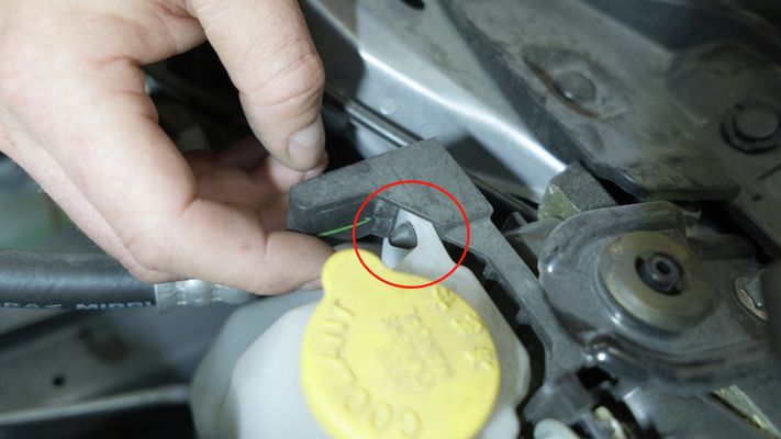
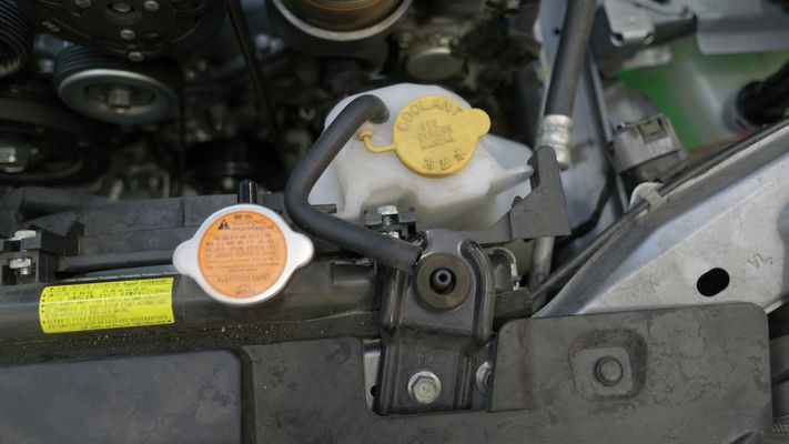
- Remove the entire coolant reservoir assembly.
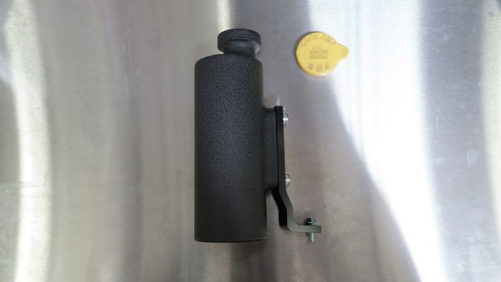
- Attach the coolant reservoir bracket to the coolant reservoir using the provided (2) 6mm socket head cap screws with washers and (1) flange head bolt.
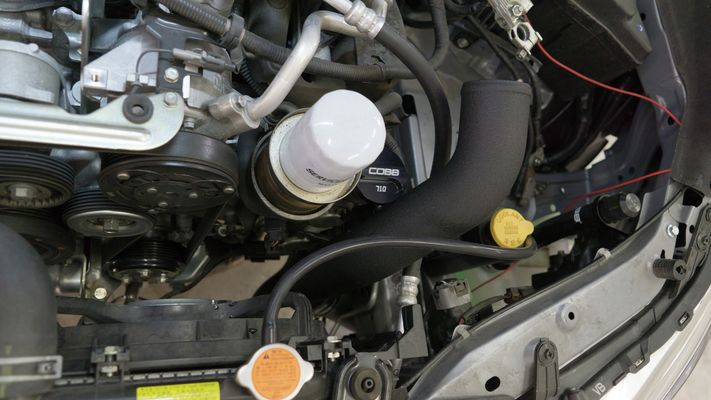
- Install the coolant reservoir in the engine bay.
- Cut the provided vacuum hose to 22" of length.
- Trim one edge of the vacuum hose to a 45 degree angle.

- Insert the angled tip of the vacuum hose through the top opening of the coolant reservoir until it touches the bottom.
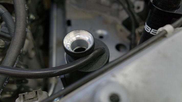
- Connect the opposite end of the vacuum hose to the radiator.
- Fill the coolant reservoir with coolant until it's 1/2-3/4 full.
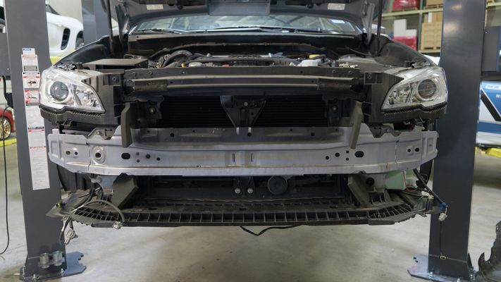
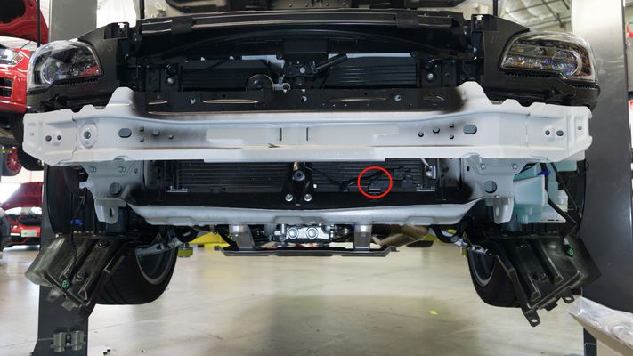
Install New Bumper Beam
- Install the new bumper beam to the FMIC core outside of the car.
- Using the provided hardware, bolt the bumper beam to the FMIC core. There will be (2) 12mm bolts and (2) 12mm nuts on each side.
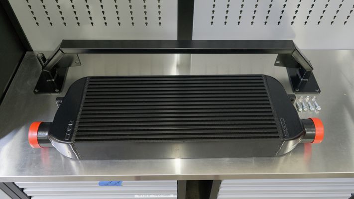
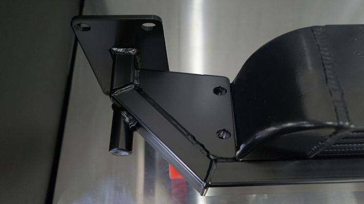

- Using the provided hardware, bolt the bumper beam to the FMIC core. There will be (2) 12mm bolts and (2) 12mm nuts on each side.
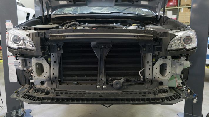
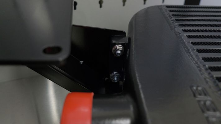
- Install the bumper beam with the attached FMIC to the car. You will be using the factory (4) 8mm bolts with 12mm heads on each side.
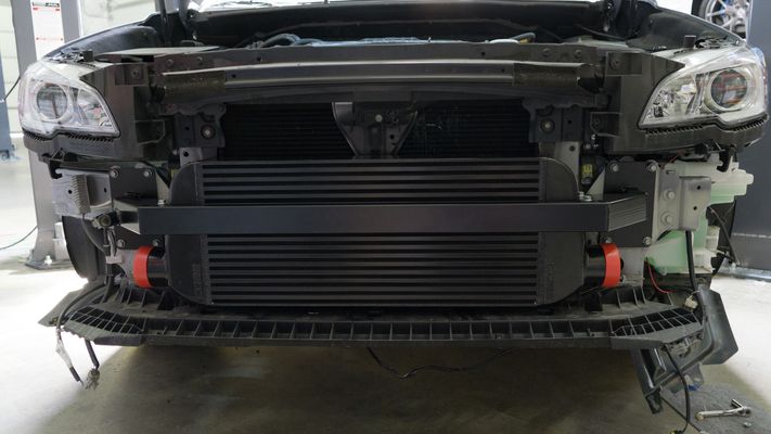
- If you wish to use the COBB logo stencil, now is a good time to paint your intercooler.
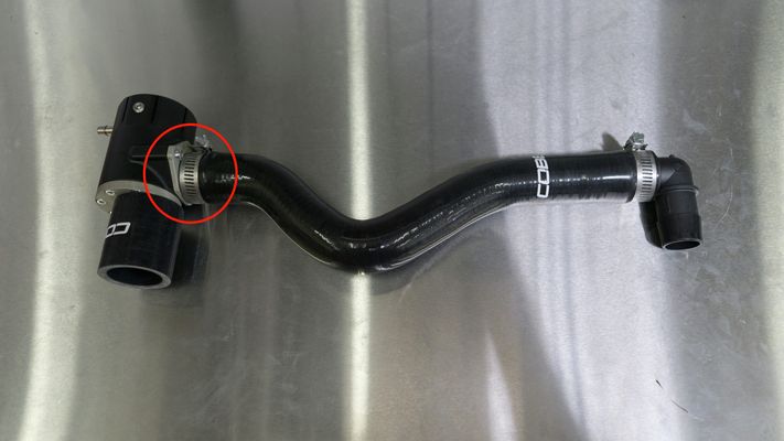
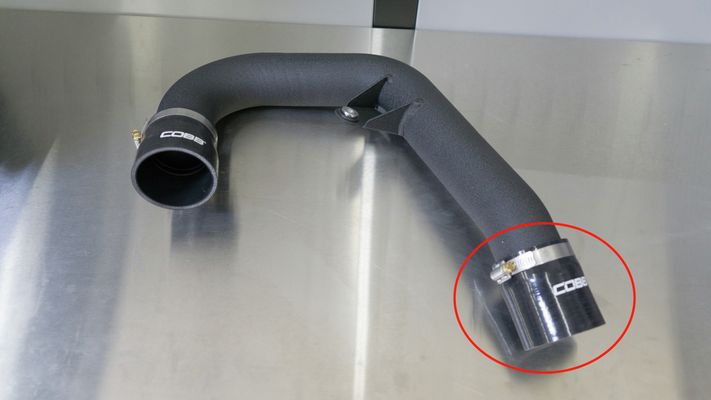
Install Hot Side Piping
(1) Upper intercooler pipe
(1) Lower intercooler pipe
(1) 2" - 2.5" silicone reducer
(1) 3" - 2.5" silicone reducer
(1) BPV recirculation 1” silicone coupler
(1) BPV to hot pipe 35mm silicone coupler
(2) #44 clamps
(1) #36 clamp
(2) #24 clamp
(2) #16 clamp
(1) #48 clamp
(1) 1” plastic elbow
(1) crankcase vent hose adapter
(2) feet 0.5” diameter silicone hose
(4) feet 6mm vacuum hose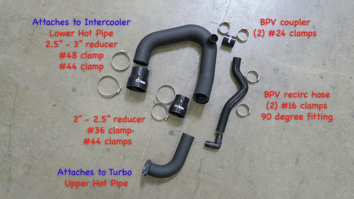
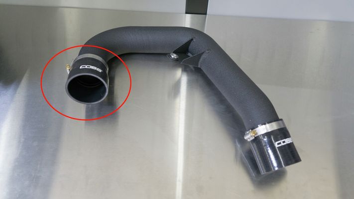
- Transfer the o-ring from the OEM charge pipe to the COBB upper intercooler pipe.
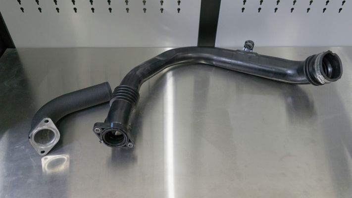
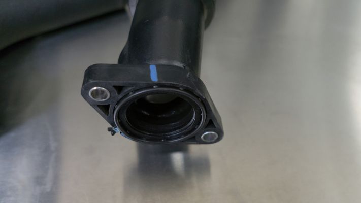
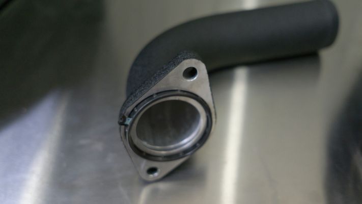
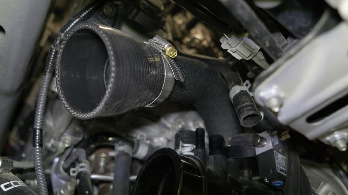
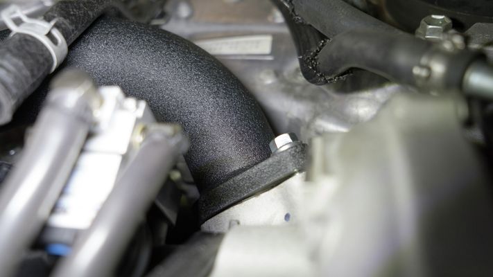
- Attach the 2.5" - 2" silicone reducer to the upper intercooler pipe using a #36 clamp. Then secure the upper hot pipe to the turbo with (2) M8x25mm flanged bolts.
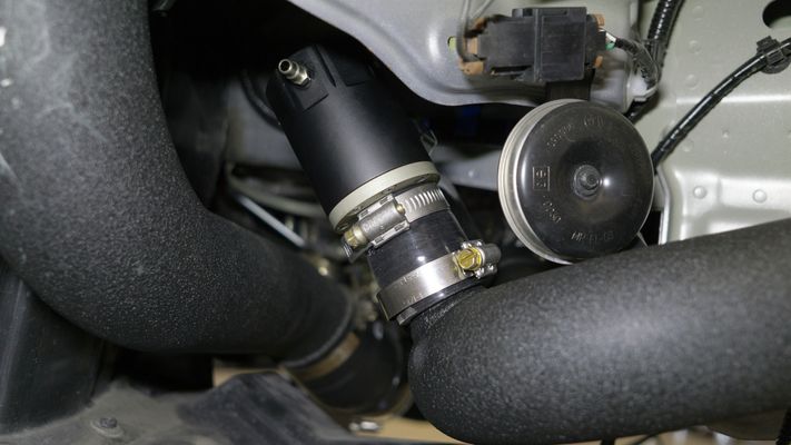
- Attach the BPV recirculation silicone to the BPV using #16 clamp.
- Attach the BPV recirculation silicone to the 1” 90 degree fitting using a #16 clamp.
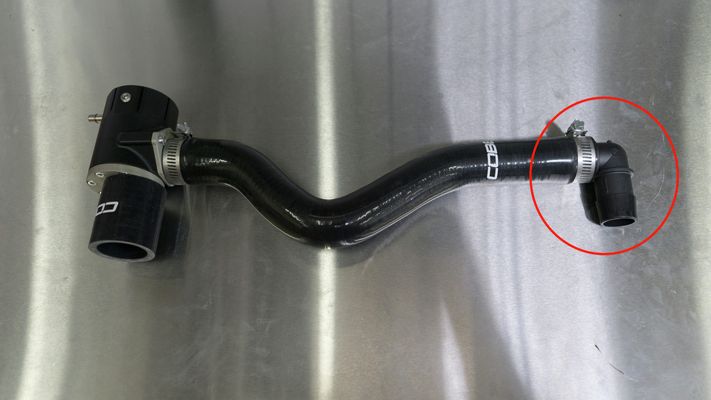
- Attach the BPV coupler to the BPV using a #24 clamp.
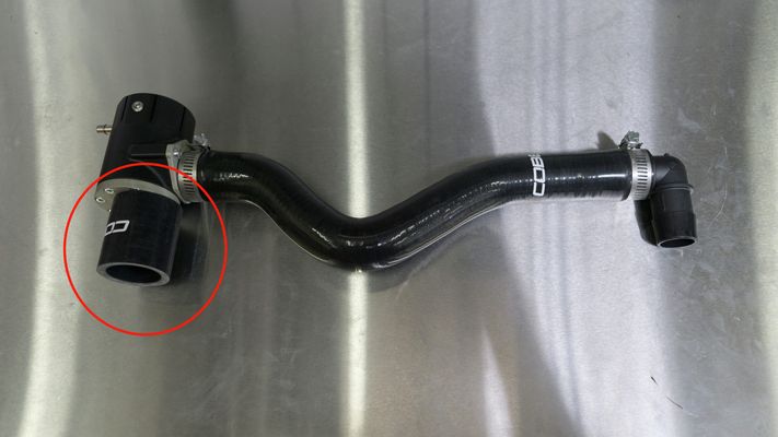
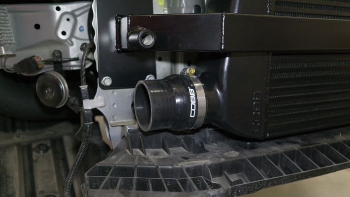
- Attach a 3" - 2.5" silicone reducer to the intercooler using a #48 clamp.
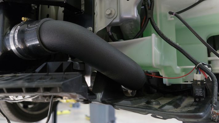
- Attach the lower intercooler pipe to the intercooler using a #44 clamp.
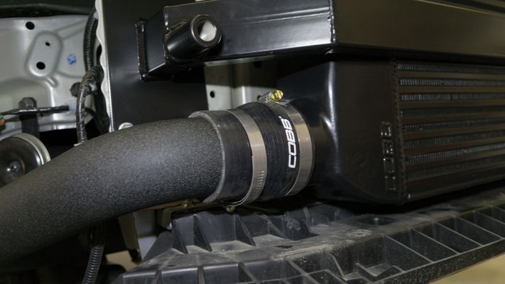
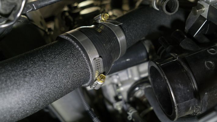
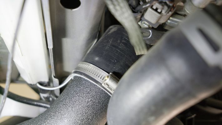
- Attach the lower intercooler pipe to the BPV coupler using a #36 clamp.
- Attach the lower intercooler pipe to the upper intercooler pipe using a #36 clamp.
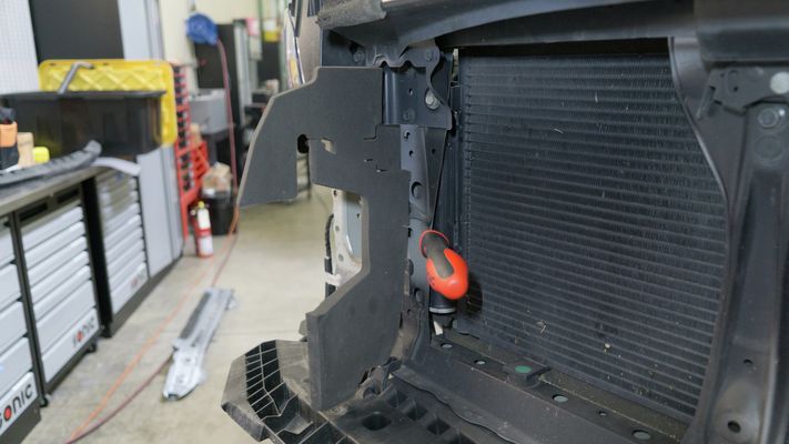
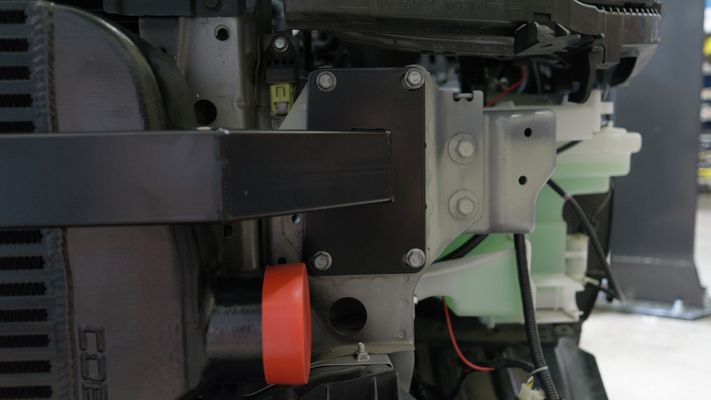
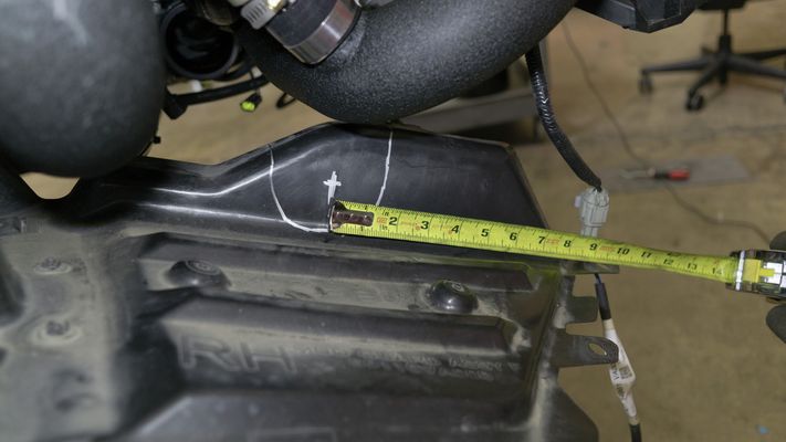
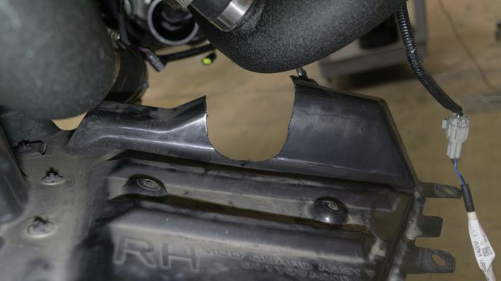
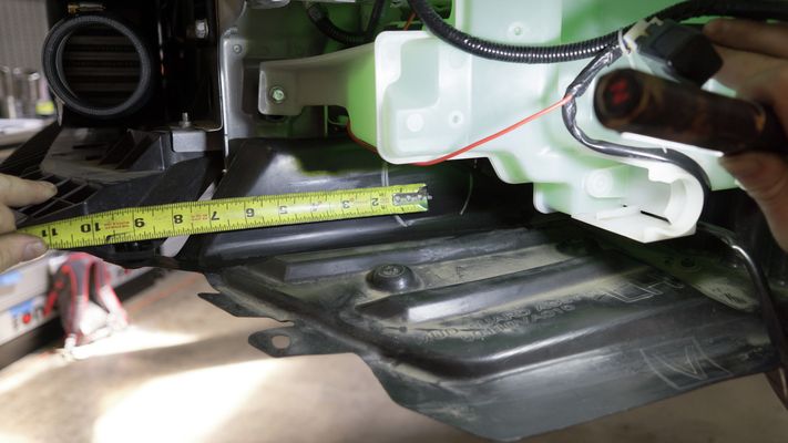
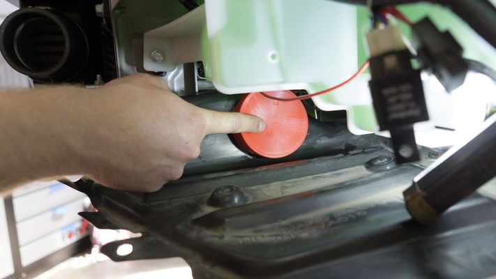
- Measure about 9.5” from the front screw that holds the wheel well tray on. You can then use the orange intercooler end tank cap to trace a cutout from the middle of the mark. Cut out the traced section from the tray.
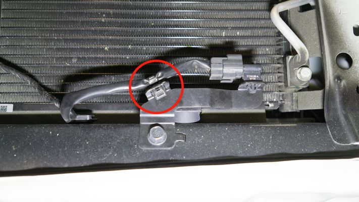
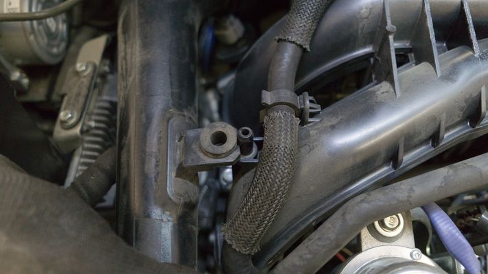
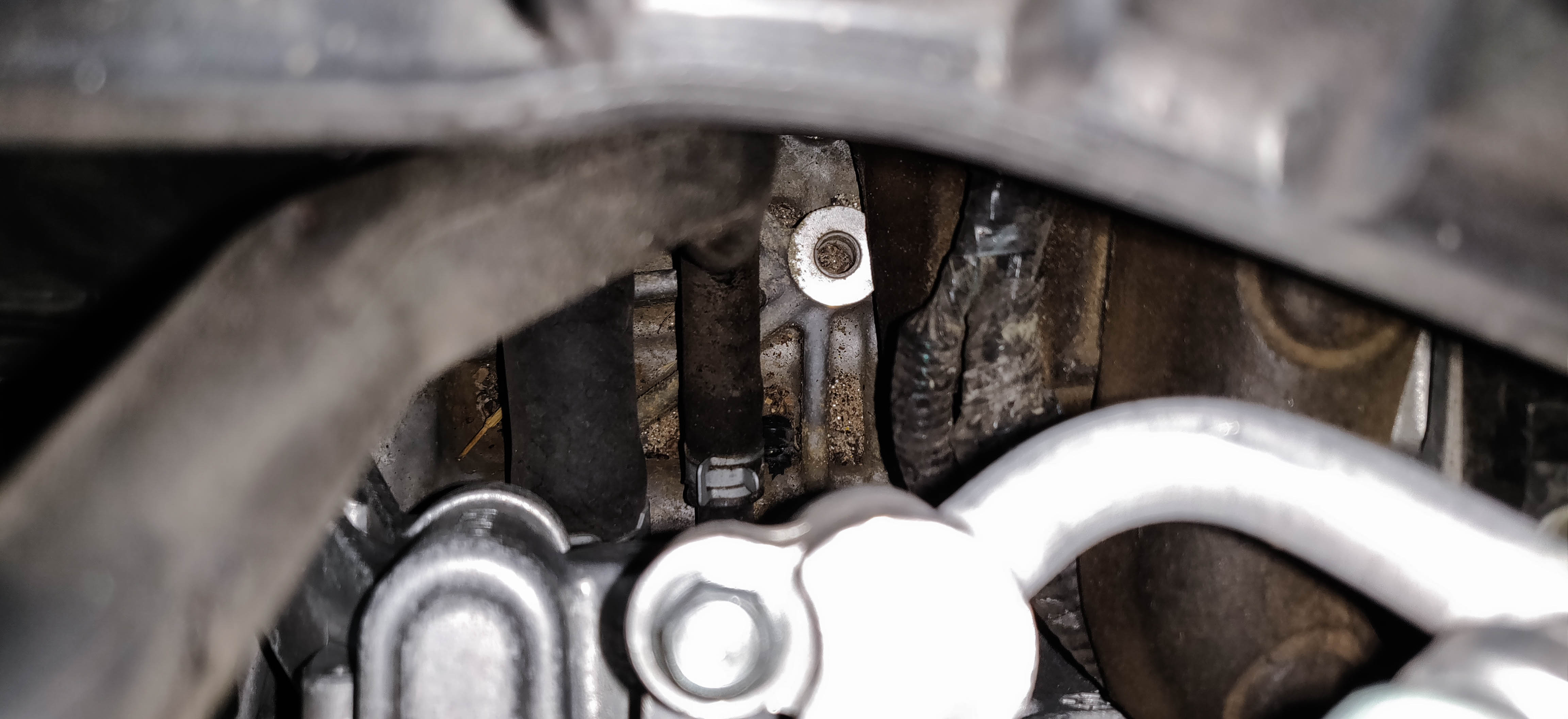
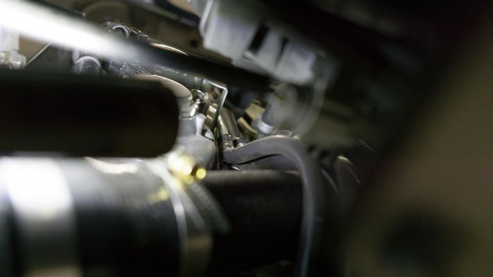
- Release the breather hose by removing the (2) plastic Phillips head push pins.
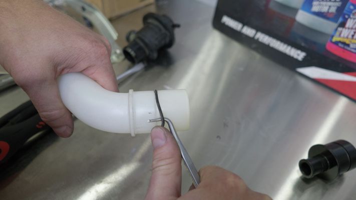
Cut the breather hose so it’s in line with the adjacent hardline (helps to mark it with a silver Sharpie or similar).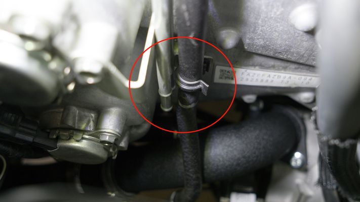
Insert the crankcase vent hose adapter.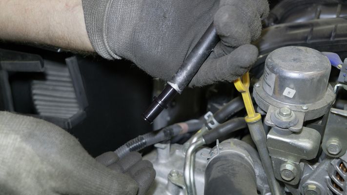
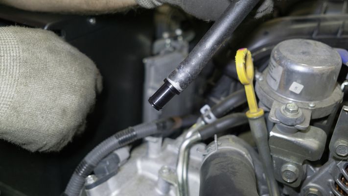
Cut a 9.5” length of silicone hose. - Attach the cut hose to the crankcase vent hose and turbo inlet.
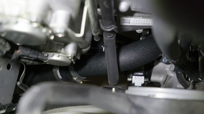
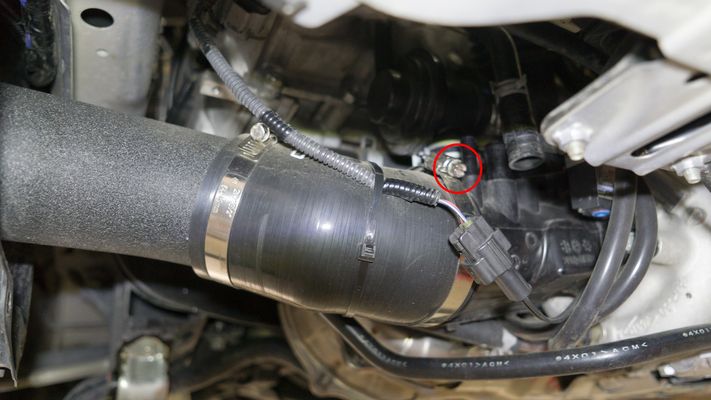
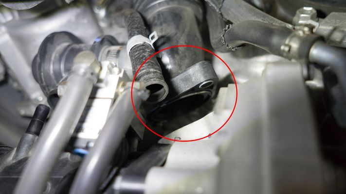
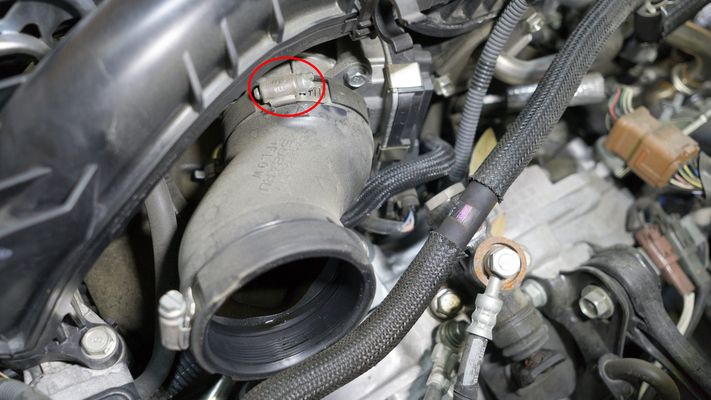
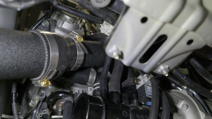
 Unhook the tube from the turbo inlet side and the connector underneath the AC Compressor. On the 18+ models you'll need to undo the electrical connection and remove the sensor assembly from the inlet with the hose. Removing the hose clamp from the side with the AC is sometimes easier to cut the rubber out from under the permanent metal ring, then remove the ring after the hose is out.
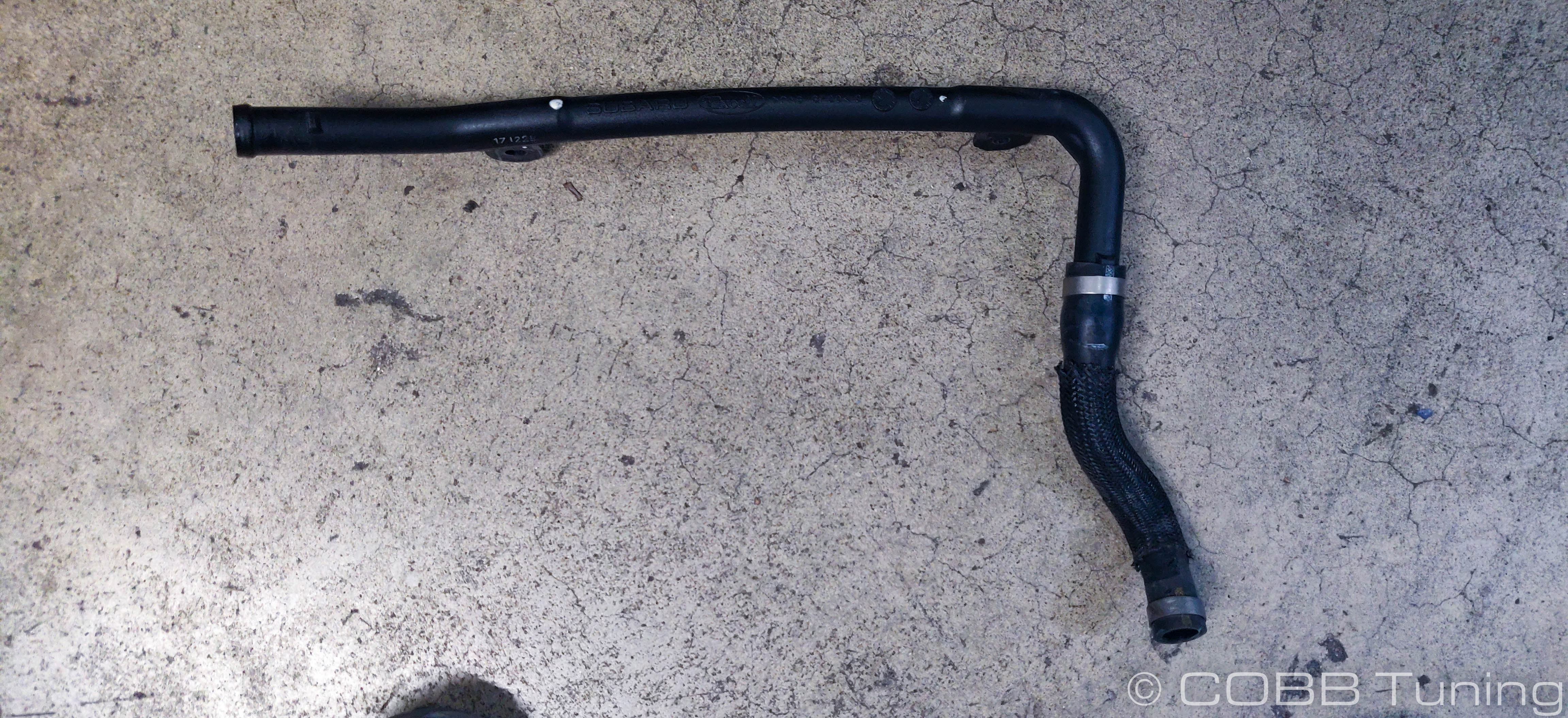
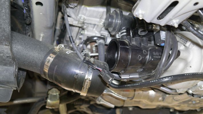
- Using the supplied silicon hose and the factory clamps, connect one end of the hose underneath the AC compressor, and run the other line to the turbo inlet. On 18+ models install the white blow-by sensor into the length of hose before installing it on the inlet.


- Cut a 10” length of silicone hose.
- Attach the cut hose to the respective breather locations. Be careful not to mix up the BPV reference.
- Cut 25” of 6mm vacuum hose.
- Attach the vacuum hose to the BPV from the hard line.
- Tighten all clamps.
Install Cold Side Intercooler Piping
(1) Upper intercooler pipe
(1) Middle intercooler pipe
(1) Lower intercooler pipe
(1) 2.75” - 2.5” silicone reducer
(2) 2.5” silicone coupler
(1) 3” - 2.5” silicone reducer
(2) #48 clamps
(6) #44 clamps
(1) Aluminium insert
(1) Rubber isolator
(1) M8x25 bolt

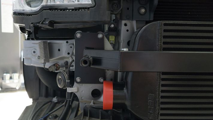
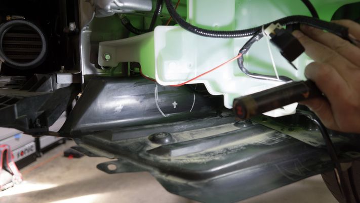
- Measuring about 7.5” from the front screw that holds the wheel well tray to the front of the car, place the orange intercooler inlet cap over the center of the mark. Trace the cap and cut out the marked hole.
- Attach the 3" - 2.5" silicone reducer to the intercooler using a #48 clamp.
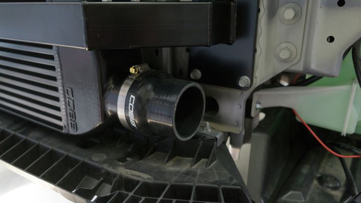
- Attach the lower intercooler pipe using a #44 clamp.
- Attach a 2.5” silicone coupler to the lower intercooler piping using a #44 clamp.
- Attach the middle intercooler pipe using a #44 clamp.
- Attach a 2.5” silicone coupler to the upper intercooler pipe using a #44 clamp.
- Attach a 2.75" - 2.5" silicone reducer to the upper intercooler pipe using a #44 clamp.
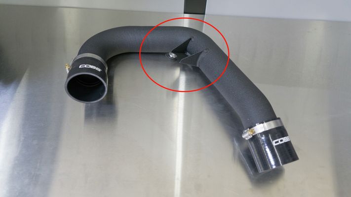
- Insert the rubber isolator into the upper intercooler bracket and then insert the aluminum insert.
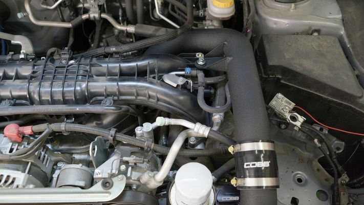
- Attach the assembled upper intercooler pipe to the throttle body and middle intercooler piping. Use a #44 clamp on the side attaching to the middle intercooler piping and a #48 clamp on the side attaching to the throttle body.

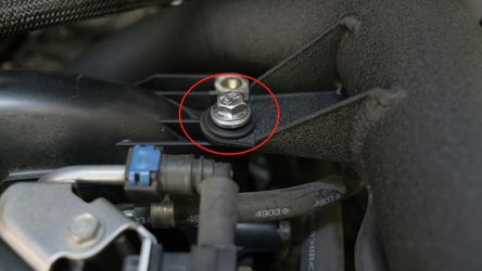
- Attach the upper intercooler bracket using the provided M8x25 bolt.
- Tighten all clamps.
Trim Undertray
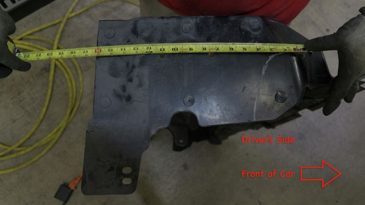
- Each application will be slightly different, but as a rule of thumb, measure and trim on the driver side of the undertray, as pictured.
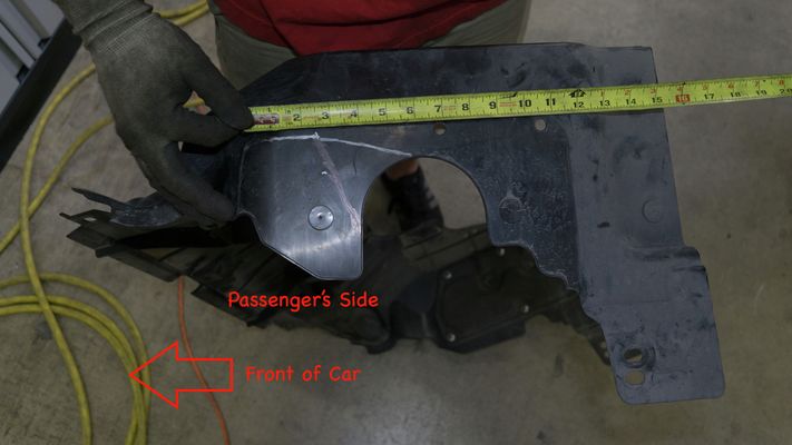
- Measure and trim on the passenger side of the undertray, as pictured.
Reinstall Bumper
- Gently set the bumper in front of the car.
- Reconnect the fog light connectors.
- Gently line up and attach the bumper back to the body.
- Note: Be careful of the pressure clips on the edges of the bumper so as to not scratch your wheel arches.
- Note: Be careful of the pressure clips on the edges of the bumper so as to not scratch your wheel arches.
- Replace the black trim/weatherstripping on top of the bumper in the engine bay.
- Insert (3) push pins and (6) 10mm bolts.
- Insert (1) push clip on the driver side wheel well.
- Insert (1) push clip on the passenger side wheel well.
- On the bottom of the bumper, insert the (6) push clips.
- Install the skid plate by bolting (4) 12mm bolts.
- Install the undertray.
- Secure the lower wheel well tray by screw (1) Phillips head screw on the passenger side.
- Secure the lower wheel well tray by screw (1) Phillips head screw on the driver side.
- Insert (7) plastic push type retainers.
- Secure the (2) 12mm bolts.
- Insert the (3) flathead push-clips from the driver wheel well.
- Insert the (3) flathead push-clips form the passenger wheel well.
- Secure the lower wheel well tray by screw (1) Phillips head screw on the passenger side.
Final Verification
- Confirm that all clamps are tight.
- Conduct a pressurized smoke test to look for any leaks.
- Flash the appropriate map for your new modification.
- Enjoy!
Links
Subaru Installation Instructions
Main Installation Instruction Repository for Subaru Parts
Link to Subaru Map Notes to see what map you should be on given the parts you've added
| Insert excerpt | ||||||
|---|---|---|---|---|---|---|
|