 Image Removed
 Image Removed
...
Image Added
Image Added
Ford EcoBoost Speed Density Guide
Version 1.0
5/4/17
Introduction
Note: This guide covers CCF Speed Density for the Ford EcoBoost engines.
| Anchor |
|---|
| _Toc311462507 |
|---|
| _Toc311462507 |
|---|
|
| Anchor |
|---|
| __RefHeading__3524_178852463 |
|---|
| __RefHeading__3524_178852463 |
|---|
|
OverviewThe CCF Speed Density feature is a powerful yet easy-to-use solution that brings simplified Speed Density tuning into the Ford engine control unit (ECU) and can be used to entirely replace the existing factory SD models. It is highly customizable and includes features such as real-time tuning to aid in a speedy and efficient tuning process.
| Anchor |
|---|
| _Toc311462508 |
|---|
| _Toc311462508 |
|---|
|
| Anchor |
|---|
| __RefHeading__3526_178852463 |
|---|
| __RefHeading__3526_178852463 |
|---|
|
UsesCCF Speed Density (SD) has a number of potential uses that can improve the tuning capability for particular set-ups:
...
| Anchor |
|---|
| _Toc311462509 |
|---|
| _Toc311462509 |
|---|
|
| Anchor |
|---|
| __RefHeading__3528_178852463 |
|---|
| __RefHeading__3528_178852463 |
|---|
|
Supported Vehicles ListThe following vehicles designed for and sold in all regions unless otherwise noted are supported:
...
| Anchor |
|---|
| _Toc311462510 |
|---|
| _Toc311462510 |
|---|
|
| Anchor |
|---|
| __RefHeading__3530_178852463 |
|---|
| __RefHeading__3530_178852463 |
|---|
|
Glossary of Acronyms- ECT = Engine Coolant Temperature
- ECU = Engine Control Unit
- CAT = Charge Air Temperature
- MCT = Manifold Charge Temperature
- IC = Intercooler
- MAP = Manifold Absolute Pressure
- RPM = Revolutions Per Minute (referring to engine speed)
- SD = Speed Density
- VE = Volumetric Efficiency
- WBO2 Sensor = Wideband Oxygen Sensor
| Anchor |
|---|
| _Toc311462511 |
|---|
| _Toc311462511 |
|---|
|
| Anchor |
|---|
| __RefHeading__3532_178852463 |
|---|
| __RefHeading__3532_178852463 |
|---|
|
FeaturesThe following is a list of the key features of CCF Speed Density (SD):
...
| Anchor |
|---|
| _Toc311462512 |
|---|
| _Toc311462512 |
|---|
|
| Anchor |
|---|
| __RefHeading__3534_178852463 |
|---|
| __RefHeading__3534_178852463 |
|---|
|
Hardware RequirementsThe following minimum hardware requirements must be met in order to use the SD feature:
...
| Anchor |
|---|
| _Toc311462513 |
|---|
| _Toc311462513 |
|---|
|
| Anchor |
|---|
| __RefHeading__3536_178852463 |
|---|
| __RefHeading__3536_178852463 |
|---|
|
Warnings| Anchor |
|---|
| _Toc311462514 |
|---|
| _Toc311462514 |
|---|
|
| Anchor |
|---|
| __RefHeading__3538_178852463 |
|---|
| __RefHeading__3538_178852463 |
|---|
|
OFF-ROAD USE ONLYSome or all of the features and modifications discussed in this guide may not be legal to use outside of off-road racing applications. Always consult local, state and federal laws to determine what is legal for your particular situation.
| Anchor |
|---|
| _Toc311462515 |
|---|
| _Toc311462515 |
|---|
|
| Anchor |
|---|
| __RefHeading__3540_178852463 |
|---|
| __RefHeading__3540_178852463 |
|---|
|
READ ALL DOCUMENTATION BEFORE TUNINGCCF SD for Ford has been designed with the purpose of coming up with the best implementation for the unique attributes of the Ford ECU, while allowing for an easy and simplified conversion from the OEM SD models. CCF SD is not like other SD systems that you may be familiar with, including even COBB implementations for other platforms. As such, it is critical that you read through this guide and understand how CCF SD for EcoBoost works before attempting to tune. If you have any questions, we are always willing to help.
| Anchor |
|---|
| _Toc311462516 |
|---|
| _Toc311462516 |
|---|
|
| Anchor |
|---|
| __RefHeading__3542_178852463 |
|---|
| __RefHeading__3542_178852463 |
|---|
|
SD IS NOT FOR INEXPERIENCED FORD TUNERSThere are many unique qualities to Ford ECU logic that can make it challenging for someone new to the platform. If you are new to Ford tuning, it is recommended that you first become proficient at tuning OEM stock turbo set-ups before tackling SD tunes. OEM tuning can be much more forgiving to mistakes than SD tuning.
| Anchor |
|---|
| _Toc311462518 |
|---|
| _Toc311462518 |
|---|
|
| Anchor |
|---|
| __RefHeading__3546_178852463 |
|---|
| __RefHeading__3546_178852463 |
|---|
|
MANIFOLD PRESSURE SENSOR CHECK ENGINE LIGHT ERRATIC LOAD CALCULATIONAny diagnostic trouble code (DTC) related to the manifold pressure sensor will cause the Ford ECU to revert to the OEM tables (as a failsafe). This can result in an erroneous load calculation if the OEM calibrations settings were not altered. If this occurs when the vehicle is accelerating, a lean condition and incorrect timing can result. It will also likely cause the engine to eventually stall. If there is the possibility that any of the MAP sensor related DTCs (P0068, P0107, or P0108) could be triggered, it is critical that those DTCs are disabled in the tune. The installation of an aftermarket MAP sensor (required for SD if the factory MAP sensor is not sufficient) will make it more likely for these DTCs to be triggered, even though there may be nothing wrong with the sensor itself. Please see "Tuning SD – Initial Map Configuration" section for more details.
| Anchor |
|---|
| _Toc311462519 |
|---|
| _Toc311462519 |
|---|
|
| Anchor |
|---|
| __RefHeading__3548_178852463 |
|---|
| __RefHeading__3548_178852463 |
|---|
|
ENGINE HARDWARE CHANGES MAY REQUIRE A RE-TUNE FOR SDIt is important to understand that after the SD tune is complete for a given car, any further changes to engine hardware that impacts airflow efficiency in or out of the engine can potentially require tweaking or re-tuning of the VE table to avoid fueling/timing issues (due to incorrectly calculated SD load). Additionally, mechanical issues, such as intake/exhaust leaks, and issues related to the aging of the motor, such as combustion deposits and loss of compression, can also impact actual VE. It is highly recommended that a permanent wideband o2 sensor and gauge is installed in the vehicle and that the driver understands how to read the gauge and determine what is normal for their tune.
| Anchor |
|---|
| _Toc311462520 |
|---|
| _Toc311462520 |
|---|
|
| Anchor |
|---|
| __RefHeading__3550_178852463 |
|---|
| __RefHeading__3550_178852463 |
|---|
|
POTENTIAL RISKS FOR SD WITH A HEAT SOAKED CAT SENSORAny SD calculation, including CCF SD, requires an input for cylinder charge temperature, which is critical to the determination of accurate aircharge via SD. The estimation of cylinder change temperature is accomplished for CCF SD via the CAT sensor input. Generally, when the CAT sensor is in the recommended location (post-IC), the vehicle is moving and the driver is on the throttle, the CAT input can be a fairly reliable representation of actual cylinder charge temp. However, when the vehicle is sitting still (or at low speeds) and the driver is off the throttle (or low throttle), or the vehicle has been sitting with the engine off and a hot engine bay for a period of time, there is the potential for the CAT sensor to become heat soaked. That is, the sensor now reads higher than the actual intake air temp. When SD is active, this would cause the calculated SD aircharge (as well as load) to be lower than it should be, causing the car to run lean (and with generally more timing advance). This effect may subside after the vehicle gets moving and throttle (as well as MAP) increases, but it will generally not be an instantaneous improvement. Knowing this, we have implemented the In-Cylinder MCT Compensation feature so these conditions can be accommodated. Please make sure to take advantage of this feature to avoid heat soak based issues.
| Anchor |
|---|
| _Toc311462521 |
|---|
| _Toc311462521 |
|---|
|
| Anchor |
|---|
| __RefHeading__3552_178852463 |
|---|
| __RefHeading__3552_178852463 |
|---|
|
SD Installation StepsBefore tuning with SD, you'll first need to update your Accesstuner software and Accessport firmware to versions compatible with the SD feature as follows. Always make sure to periodically check for future updates.
...
- You may now either open your existing map or simply use the default stock mapping in Accesstuner. Make any initial changes to this map that you wish to start from for SD (see "Tuning SD – Initial Map Configuration" later in this document).
- Save your map. This map will now have the SD feature.
- Reflash the new SD map to the car via the Accessport or.
- The car is now ready to be tuned via SD.
SD Basics
| Anchor |
|---|
| _Toc311462522 |
|---|
| _Toc311462522 |
|---|
|
| Anchor |
|---|
| __RefHeading__3554_178852463 |
|---|
| __RefHeading__3554_178852463 |
|---|
|
What is Speed Density?The Ford ECU, as well as any engine management solution, needs to determine the mass of air entering the engine in order to determine the correct amount of fuel to inject for a given desired fueling target. With the Ford ECU, it is represented in terms of cylinder airmass (lbm/event), which, along with engine speed (RPM), is used to determine load (%). For the Ford ECU, load is not only used to determine the proper injector pulse width, but also the desired fueling/timing targets. The modern factory EcoBoost determines aircharge via the manifold absolute pressure (MAP) sensor and pre-calibrated computer modeling.
...
| Anchor |
|---|
| _Toc311462523 |
|---|
| _Toc311462523 |
|---|
|
| Anchor |
|---|
| __RefHeading__3556_178852463 |
|---|
| __RefHeading__3556_178852463 |
|---|
|
What is Volumetric Efficiency?Simply put, it is the amount of air inducted into the engine relative to the engine's displacement. An engine is essentially an air pump and volumetric efficiency (VE) defines how efficient that process is. A volumetric efficiency of 100% would indicate that the amount of air inducted is the same as the engine displacement (at standard conditions) for a given engine cycle. If all engines always operated at 100% VE, there would be no need to account for VE in determining the SD aircharge. But, this is far from the case.
...
| Anchor |
|---|
| _Toc311462524 |
|---|
| _Toc311462524 |
|---|
|
| Anchor |
|---|
| __RefHeading__3558_178852463 |
|---|
| __RefHeading__3558_178852463 |
|---|
|
Volumetric Efficiency TableThe VE table is the primary means by which an SD tune is accomplished for a given car. Once tuned, changes to engine hardware and/or mechanical/aging issues that arise (as described in the section above) may require re-tuning of the VE table. What areas of the table that need to re-tuned or tweaked is going to depend on the change itself and how it impacts actual VE across a range of MAP and RPM.
...
| Anchor |
|---|
| _Toc311462525 |
|---|
| _Toc311462525 |
|---|
|
| Anchor |
|---|
| __RefHeading__3560_178852463 |
|---|
| __RefHeading__3560_178852463 |
|---|
|
SD ActivationCCF SD is optional!
To use the system simply turn it on in the calibration using the Master Switch (Speed Density).
...
| Anchor |
|---|
| _Toc311462526 |
|---|
| _Toc311462526 |
|---|
|
| Anchor |
|---|
| __RefHeading__3562_178852463 |
|---|
| __RefHeading__3562_178852463 |
|---|
|
Tuning SD – Mechanical ConfigurationBefore jumping in and starting tuning, make sure the car meets the minimum hardware requirements outlined in the "Hardware Requirements" section found earlier in this document. Failure to do so can result in an inconsistent tune as well as potential engine damage.
| Anchor |
|---|
| _Toc311462527 |
|---|
| _Toc311462527 |
|---|
|
| Anchor |
|---|
| __RefHeading__3564_178852463 |
|---|
| __RefHeading__3564_178852463 |
|---|
|
Tuning SD – Getting Started- Installing SD – Make sure an SD map has been reflashed to the car's ECU and you have the latest SD-capable software and firmware updates as outlined in the "SD Installation" section earlier in this document.
- Opening Map – Run the Accesstuner software and select the ECU of the car you are tuning. Open the SD map you reflashed to the vehicle.
| Anchor |
|---|
| _Toc311462528 |
|---|
| _Toc311462528 |
|---|
|
| Anchor |
|---|
| __RefHeading__3566_178852463 |
|---|
| __RefHeading__3566_178852463 |
|---|
|
Tuning SD – Initial Map Configuration| Anchor |
|---|
| _Toc311462529 |
|---|
| _Toc311462529 |
|---|
|
| Anchor |
|---|
| __RefHeading__3568_178852463 |
|---|
| __RefHeading__3568_178852463 |
|---|
|
Airflow and Load LimitsBecause most of the factory logic is retained for CCF SD, factory limits that cap airflow and load are still applied. While not critical that these limits are raised for your tune, be aware that throttle closures will occur if they are hit. This is true regardless of whether CCF SD is enabled or not.
| Anchor |
|---|
| _Toc311462530 |
|---|
| _Toc311462530 |
|---|
|
| Anchor |
|---|
| __RefHeading__3570_178852463 |
|---|
| __RefHeading__3570_178852463 |
|---|
|
Manifold Pressure Sensor Diagnostic Trouble CodesIf a check engine light is set related to the manifold absolute pressure (MAP) sensor, the ECU will switch to the OEM speed density tables.
...
| Anchor |
|---|
| _Toc311462532 |
|---|
| _Toc311462532 |
|---|
|
| Anchor |
|---|
| __RefHeading__3574_178852463 |
|---|
| __RefHeading__3574_178852463 |
|---|
|
Conservative Fuel and Timing MapsIt is important to consider using conservative fuel and timing maps during the initial SD tuning phase. When starting your tune, the VE table will not be perfect until you've had a chance to dial it in. While you are tuning the table, any error from actual VE will not only result in the incorrect fueling, but also the incorrect load values. If the VE for a given cell in your table is less than actual VE, this will result in load that is less than actual load. Because the timing tables use load as an input, the timing advance will generally be higher than intended in this case. This issue would also impact the cam timing (VCT) tables as well as any other table that uses load as an input. If the VE for a given cell in your VE table is greater than actual VE, the opposite will occur, where load will be greater than actual. This is why you generally want to bias your VE values to a higher estimation of VE when starting out, rather than a lower one.
| Anchor |
|---|
| __RefHeading__4641_303041327 |
|---|
| __RefHeading__4641_303041327 |
|---|
|
| Anchor |
|---|
| __RefHeading__3576_178852463 |
|---|
| __RefHeading__3576_178852463 |
|---|
|
Fuel| Anchor |
|---|
| _Toc311462533 |
|---|
| _Toc311462533 |
|---|
|
Injector Scale and LatencyTuning for new injectors for CCF SD is no different than the factory process. As such, you will need to make sure your fuel injector settings are tuned correctly prior to tuning with SD. If you are changing injectors at the same time as changing over to SD, you'll need to at least make sure that you have reasonable starting values for the new injectors.
| Anchor |
|---|
| _Toc311462534 |
|---|
| _Toc311462534 |
|---|
|
| Anchor |
|---|
| __RefHeading__3578_178852463 |
|---|
| __RefHeading__3578_178852463 |
|---|
|
Engine DisplacementCCF SD uses engine displacement as one of the inputs to the SD airmass calculation. As such, this requires that you input the correct displacement of the motor you are tuning via the Engine Displacement (Standardized Air Charge) table in the COBB Custom Features → Speed Density group. This should be the closest value (in liters) to the car's actual engine displacement for a single cylinder. The default value varies by application but is derived from the OEM calibration settings. Also note, changing values in this table will also show a change to the Standardized Air Charge (in the OEM Speed Density Tables group) as it's a converted representation of the same table. The final displacement will show when viewing the Engine Displacement realtime table, and can be modified to fine tune displacement as needed (remember to populate the final version divided by the number of cylinders).
| Anchor |
|---|
| _Toc311462535 |
|---|
| _Toc311462535 |
|---|
|
| Anchor |
|---|
| __RefHeading__3580_178852463 |
|---|
| __RefHeading__3580_178852463 |
|---|
|
VE Table Axis ScalingThe default values for the MAP axis of the VE table is in 2.23 psia steps up to a maximum of 44.7 psia and the default values for the RPM axis is in 400 RPM steps up a max of 8000 RPM. You need to make sure that the maximum values are enough for the max MAP and RPM that the motor will likely see. When either RPM or MAP exceeds their corresponding max axis values, the ECU will continue to use the VE values in the last row (or column). If you need to make a change, simply re-scale the axis values in realtime and reflash those changes to the ECU when finished. Keep in mind that the MAP axis is in units of manifold absolute pressure, not relative pressure. If you wish to determine the corresponding relative pressure values (for reference) simply subtract your barometric pressure from MAP. The barometric pressure can be read via the Barometric Pressure monitor. If you are at/near sea level (barometric pressure around 14.7 psi) and you wish to quickly determine the relative pressure in your head, simply subtract 15 psi from the MAP axis value you are looking at (for example, 30 psia – 15 psi = 15 psig). This will give you a quick approximation when you wish to think in terms of relative pressure.
| Anchor |
|---|
| _Toc311462536 |
|---|
| _Toc311462536 |
|---|
|
| Anchor |
|---|
| __RefHeading__3582_178852463 |
|---|
| __RefHeading__3582_178852463 |
|---|
|
Reflash ChangesMake sure you save this map with the initial changes and reflash to the car before continuing with the tune.
| Anchor |
|---|
| _Toc311462537 |
|---|
| _Toc311462537 |
|---|
|
| Anchor |
|---|
| __RefHeading__3584_178852463 |
|---|
| __RefHeading__3584_178852463 |
|---|
|
Tuning SD – Starting Values for the VE TableThe default values for the VE table are set to 100% across the entire table. This is not meant to be a starting point to run the vehicle in SD tune. Instead, you'll want to consider coming up with initial values in the VE table that are reasonable enough to run the car in SD. The following gives suggestions on how to proceed with various scenarios.
| Anchor |
|---|
| _Toc311462538 |
|---|
| _Toc311462538 |
|---|
|
| Anchor |
|---|
| __RefHeading__3586_178852463 |
|---|
| __RefHeading__3586_178852463 |
|---|
|
Using the OEM model as a referenceIf the car runs well enough with the OEM tables, you can use the (SD) Estimated VE (OEM) monitor to aid in determining starting values for your VE table. If there are issues with the accuracy of the OEM calibration settings, or problems with the CAT sensor, MAP sensor, and/or engine displacement inputs, this will impact the accuracy of the (SD) Estimated VE (OEM) monitor.
...
| Anchor |
|---|
| _Toc311462539 |
|---|
| _Toc311462539 |
|---|
|
| Anchor |
|---|
| __RefHeading__3588_178852463 |
|---|
| __RefHeading__3588_178852463 |
|---|
|
Starting from scratchIf the OEM tables are not properly calibrated and the vehicle configuration drastically varies from stock, then there is not a means to directly estimate VE for a given car. Over time, however, you will see specific patterns in the VE table for cars you've tuned (for a given set of mods) and setting up a reasonable starting VE table for similar vehicles will not be difficult. If you have no frame of reference, however, you can start with some general guidelines. The default values in the VE table will be 100% for all cells. This will be generally too high in the lift-throttle, idle, and cruise areas (i.e. much too rich). Generally speaking, you may see more like 50%-60% in lift-throttle/idle areas and 60%-80% in cruise areas. Moderate boost may be in the 80%-90% range. Higher boost may be in the 90% to over 100% range. To stay on the conservative side of things with your starting VE table, you want to bias your estimate towards higher values rather than lower. This will reduce the chance of a lean condition when the table VE is less than actual VE. This is especially critical at higher boost where a lean condition (and greater timing advance) due to lower than actual load would be more of a problem.
| Anchor |
|---|
| _Toc311462540 |
|---|
| _Toc311462540 |
|---|
|
| Anchor |
|---|
| __RefHeading__3590_178852463 |
|---|
| __RefHeading__3590_178852463 |
|---|
|
Tuning SD – The Tables| Anchor |
|---|
| _Toc311462541 |
|---|
| _Toc311462541 |
|---|
|
| Anchor |
|---|
| __RefHeading__3592_178852463 |
|---|
| __RefHeading__3592_178852463 |
|---|
|
"Volumetric Efficiency" Table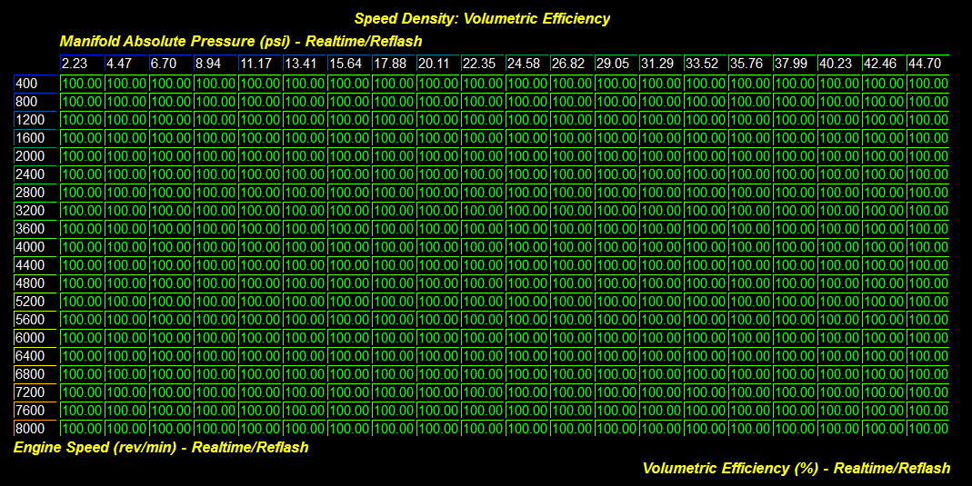
The Volumetric Efficiency table is the primary means by which the SD tune is accomplished. Once you have your starting values configured for this table (as described in the previous section), you can get to the actual tune. You'll need to make sure the SD master switch is enabled and that the car is at operating temperature. As you hit the MAP/RPM area corresponding to a given cell, if your wideband o2 (wbo2) sensor reads richer than what the ECU is targeting, you reduce VE for that cell. If your wbo2 sensor reads leaner than what the ECU is targeting, you increase VE for that cell. You continue this process until you've dialed in as much of the VE table as you can.
...
| Anchor |
|---|
| _Toc311462542 |
|---|
| _Toc311462542 |
|---|
|
| Anchor |
|---|
| __RefHeading__3594_178852463 |
|---|
| __RefHeading__3594_178852463 |
|---|
|
"VE Compensation (MCT Pivot)"
Like the VE table, the VE Compensation (MCT Pivot) table is another critical component of the SD aircharge calculation. In order for our SD aircharge to be accurate, we not only need to know MAP, RPM, VE, and engine displacement, but we also need to know the temperature of the cylinder charge. Without this input and its corresponding correction, any given cell in our VE table would only be valid at the charge temperature in which it was tuned. Without this correction, if the cylinder charge temp dropped from our tuned charge temp, we would go lean and if it went up, we would go rich.
...
| Anchor |
|---|
| _Toc311462542 |
|---|
| _Toc311462542 |
|---|
|
| Anchor |
|---|
| __RefHeading__3594_178852463 |
|---|
| __RefHeading__3594_178852463 |
|---|
|
"In-Cylinder MCT Compensation"
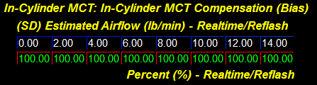
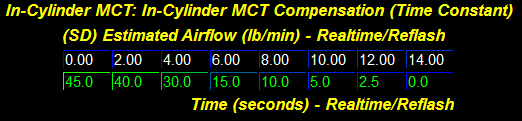
The other scenario in which the CAT reading may differ markedly from actual charge temperature is when the CAT sensor becomes heat-soaked. What happens is that the sensor itself absorbs heat from the surrounding air and intake piping and reads a temperature higher than the actual temperature of the aircharge. Generally, this effect is progressively more pronounced at lower MAP/airflow and therefore you may be more likely to see it in conditions such as stop and go driving, extended idling, or a hot restart. Because the CAT reading is higher than the charge temperature, this would cause the aircharge calculation to be less than actual and you would end up going lean (as well as causing potentially more timing advance). When MAP/airflow does increase, the heat soak effect of the sensor does not instantaneously diminish, so the heat soaked reading may continue at higher MAP for a period of time. This may present a problem if, for example, the car is subject to high loads (such as wide open throttle) soon after heat-soak of the sensor sets in. For these reasons, we have added a way to bias the charge air temperature with engine coolant temperature in a means to estimate the in-cylinder charge temperature.
...
Here is how the math for this works (note the filter is not shown here but is present):
| Mathblock |
|---|
| host | Confluence:6334724835 |
|---|
| alignment | left |
|---|
|
(SD)\ MCT\ Final=((CAT - ECT) * BIAS) + ECT |
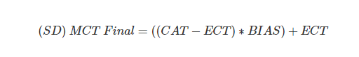 Image Added
Let's run an example, current Charge Air Temperature is 128 deg. F and Coolant Temperature is 205 deg. F, the Bias request is 80%.
...
| host | Confluence:6334724835 |
|---|
| alignment | left |
|---|
...
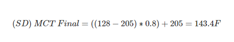 Image Added
Keep in mind though that the heat soaked CAT reading can potentially occur even at colder temps. For example, the charge temperature may be 40 deg. F and the CAT reading is 60 deg. F. This would still be a heat soak scenario (although one which would be difficult to account for) even though the temperatures are relatively mild. Be sure to adjust these tables accordingly to prevent this phenomenon from becoming an issue.
| Anchor |
|---|
| __RefHeading__3596_178852463 |
|---|
| __RefHeading__3596_178852463 |
|---|
|
| Anchor |
|---|
| _Toc311462543 |
|---|
| _Toc311462543 |
|---|
|
"VE Compensation (Base)" Table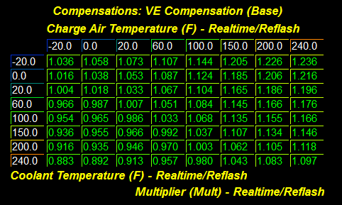
It is typically not necessary to tune the VE Compensation (Base) table as far as the ideal gas law and our SD aircharge calculation is concerned. The default values are generated from an OEM equivalent table. However, you may find some circumstances where it may be useful to tweak this table for your SD tune. One example would be more extreme coolant temperature readings (on the high end). You may want to increase correction at this extreme as this may mean a more likely heat soak scenario for the CAT sensor (high ECT likely means higher radiant engine heat). As described in the previous section, a heat soaked CAT sensor (relative to actual charge temp) will result in a lean condition with SD.
| Anchor |
|---|
| _Toc311462544 |
|---|
| _Toc311462544 |
|---|
|
| Anchor |
|---|
| __RefHeading__3598_178852463 |
|---|
| __RefHeading__3598_178852463 |
|---|
|
"VE Compensation (Barometric Pressure)" Table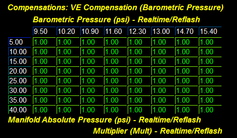
As you go up in altitude, the barometric pressure drops. The SD aircharge calculation for CCF SD accounts for this change because MAP is a part of the ideal gas law calculation and therefore, as barometric pressure decreases, MAP also decreases (all else equal) and SD aircharge will also decrease. However, exhaust gas backpressure also decreases as barometric pressure decreases, which can impact VE. As such, you may need to tune the VE Compensation (Barometric Pressure) table if the car is going to see notable changes in altitude. In addition to the barometric pressure axis, this table also has a MAP axis. This will allow you to tune the compensation against MAP where the effect of exhaust gas pressure on VE may vary.
| Anchor |
|---|
| _Toc311462549 |
|---|
| _Toc311462549 |
|---|
|
| Anchor |
|---|
| __RefHeading__3608_178852463 |
|---|
| __RefHeading__3608_178852463 |
|---|
|
Tuning SD – Post-Tune RecommendationsWhen you feel your SD tune is complete, there are several things you should consider in order to maximize the long-term reliability of the SD tune:
...
| Anchor |
|---|
| _Toc311462550 |
|---|
| _Toc311462550 |
|---|
|
| Anchor |
|---|
| __RefHeading__3610_178852463 |
|---|
| __RefHeading__3610_178852463 |
|---|
|
Tuning SD – Additional Topics| Anchor |
|---|
| _Toc311462551 |
|---|
| _Toc311462551 |
|---|
|
| Anchor |
|---|
| __RefHeading__3612_178852463 |
|---|
| __RefHeading__3612_178852463 |
|---|
|
Recommended Calibrations for Aftermarket TMAP SensorsWhen an aftermarket TMAP sensor is installed, you may need to tune the CAT sensor calibration which will be different with an aftermarket sensor as compared to the factory CAT sensor. This is done via the CAT Sensor Calibration table in the Sensor Calibrations group.
...
| Anchor |
|---|
| _Toc311462552 |
|---|
| _Toc311462552 |
|---|
|
| Anchor |
|---|
| __RefHeading__3616_178852463 |
|---|
| __RefHeading__3616_178852463 |
|---|
|
Recommended Calibrations for Aftermarket MAP SensorsWhen an aftermarket MAP/TMAP sensor is installed, you will need to set up the MAP sensor calibration appropriately. This is done via the MAP Sensor Scalar and MAP Sensor Offset tables in the Sensor Calibrations group. The Boost Pressure reading (via Accesstuner software or Accessport) should then be compared to an external boost gauge to verify accuracy before tuning SD. The recommended calibrations for some of the most popular aftermarket MAP/TMAP sensors are shown below (note: values are shown in psi). Note: These calibrations are provided for your convenience only and do not represent an endorsement for or against any particular product. Manufacturer's specifications can change at any time. It is important that you verify the sensor calibration you are going to use before tuning SD.
...
| Anchor |
|---|
| _Toc311462553 |
|---|
| _Toc311462553 |
|---|
|
| Anchor |
|---|
| __RefHeading__3618_178852463 |
|---|
| __RefHeading__3618_178852463 |
|---|
|
Forcing Open Loop FuelingIn some cases, you may find it more straightforward to temporarily force the ECU into full-time open loop fueling when tuning the VE table. This can be accomplished by the following procedure:
...
| Anchor |
|---|
| _Toc311462554 |
|---|
| _Toc311462554 |
|---|
|
| Anchor |
|---|
| __RefHeading__3620_178852463 |
|---|
| __RefHeading__3620_178852463 |
|---|
|
Long-Term Fuel TrimsYou may find it necessary (or more optimal) to manipulate how the long-term fuel trims are determined when running SD. The long-term fuel trims are determined based on patterns of short-term correction. They are calculated and applied across several airflow ranges. These ranges are determined by the A/F Learning Breakpoints (LTFT) table (under the Fuel Tables -> A/F Learning group). The following is an example:
...
| Anchor |
|---|
| _Toc311462556 |
|---|
| _Toc311462556 |
|---|
|
| Anchor |
|---|
| __RefHeading__3624_178852463 |
|---|
| __RefHeading__3624_178852463 |
|---|
|
Cam Timing (VCT) Tuning Changes and Effect on VEMost tuning changes are not going to impact VE. For example, once you have your VE table dialed in, you can make changes to timing, fuel, and boost tuning without needing to revisit the VE table due to those changes. However, there is one exception. That is changes to cam timing (VCT). Cam timing changes can definitely impact VE and will likely require you to tweak the VE table as a result. When attempting to dial-in the VE table, large changes in cam timing with small changes in load/RPM will change actual VE and you may end up with feedback loop of sorts that makes it more difficult to tune. For this reason we have added compensation tables to allow for changes made to cam timing to be accommodated for.
...
| Anchor |
|---|
| _Toc311462567 |
|---|
| _Toc311462567 |
|---|
|
| Anchor |
|---|
| __RefHeading__3646_178852463 |
|---|
| __RefHeading__3646_178852463 |
|---|
|
How to Monitor the TuneIn addition to the monitors already included for the EcoBoost, CCF SD adds new monitors specific to the feature. These will be useful in the tuning process as well as verifying/monitoring the tune once it is complete.
...
| Anchor |
|---|
| _Toc311462568 |
|---|
| _Toc311462568 |
|---|
|
| Anchor |
|---|
| __RefHeading__3648_178852463 |
|---|
| __RefHeading__3648_178852463 |
|---|
|
SD Real-Time TuningReal-Time Tunable SD Tables
Most of the new tables added for the SD feature are real-time tunable. See the "Realtime Tables" group in the Accesstuner software for a complete listing of all real-time tables for a given ECU.
| Anchor |
|---|
| __RefHeading__3656_178852463 |
|---|
| __RefHeading__3656_178852463 |
|---|
|
| Anchor |
|---|
| _Toc311462572 |
|---|
| _Toc311462572 |
|---|
|
SD MathThis section describes the math behind the CCF SD calculations which are based on the ideal gas law. It is not necessary to understand this math in order to tune SD, but some may find it interesting.
| Anchor |
|---|
| _Toc311462573 |
|---|
| _Toc311462573 |
|---|
|
| Anchor |
|---|
| __RefHeading__3658_178852463 |
|---|
| __RefHeading__3658_178852463 |
|---|
|
Ideal Gas Law – IntroductionThe ideal gas law is an equation that governs the relationship between the pressure, volume, amount and temperature of an "ideal" gas:
...
Our "ideal" gas is quite simply the air that is being ingested by the engine. For our purposes, we want to know the mass of air entering the engine. We can determine the mass of air by using a constant that dictates the mass (in lb) per mole of air (i.e. the molar mass of air, which we'll call MMA):
| Mathblock |
|---|
| host | Confluence:6334724835 |
|---|
| alignment | left |
|---|
|
Airmass\ (lb)=N(moles) * MMA(lb/mole) |
Because 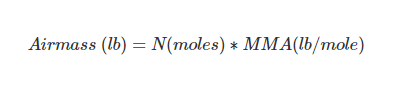 Image Added
Because N = PV/RT, we can express this as:
| Mathblock |
|---|
| host | Confluence:6334724835 |
|---|
| alignment | left |
|---|
|
Airmass\ (lb)=(\frac{PV}{RT}) * MMA |
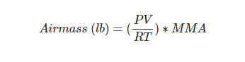 Image Added
| Anchor |
|---|
| _Toc311462574 |
|---|
| _Toc311462574 |
|---|
|
| Anchor |
|---|
| __RefHeading__3660_178852463 |
|---|
| __RefHeading__3660_178852463 |
|---|
|
Ideal Gas Law – Real-World InputsGiven the above equation, we need input data for pressure (P), volume (V), and temperature (T). Given our engine scenario, these inputs would be determined as follows:
...
V = Volume = Displacement of the engine (in liters).
...
| host | Confluence:6334724835 |
|---|
| alignment | left |
|---|
...
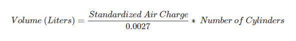 Image Added
T = Temperature = Cylinder charge temperature in Kelvin as estimated by the charge air temperature (CAT) sensor. Temperature in Kelvin can be determined as follows: CAT Celsius + 273.15
...
| Anchor |
|---|
| _Toc311462575 |
|---|
| _Toc311462575 |
|---|
|
| Anchor |
|---|
| __RefHeading__3662_178852463 |
|---|
| __RefHeading__3662_178852463 |
|---|
|
Ideal Gas Law – Volumetric Efficiency
| Mathblock |
|---|
| host | Confluence:6334724835 |
|---|
| alignment | left |
|---|
|
Estimated\ Aircharge\ (lbm/event)=\frac{MAP * DISP * MMA}{R * CAT} |
...
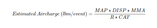 Image Added
The above equation is only valid for our engine example if volumetric efficiency is always 100%, which is obviously not the case. We must therefore add VE and its compensations as correction factors.
| Mathblock |
|---|
| host | Confluence:6334724835 |
|---|
| alignment | left |
|---|
|
Estimated\ Aircharge\ (lbm/event)=\frac{MAP * DISP * MMA * COMPS * VE}{R * CAT} |
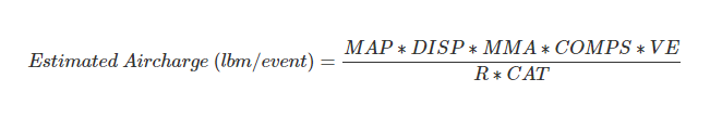 Image Added
| Anchor |
|---|
| _Toc311462576 |
|---|
| _Toc311462576 |
|---|
|
| Anchor |
|---|
| __RefHeading__3664_178852463 |
|---|
| __RefHeading__3664_178852463 |
|---|
|
Ideal Gas Law – Airflow MassTo determine the air entering the cylinder per unit of time, we add RPM as an input. Because the crankshaft rotates 720 degrees (i.e. two revolutions) for a full stroke, the number of times air is entering the cylinders per event is included and used for our ultimate conversion into an estimated airflow mass in lb/min:
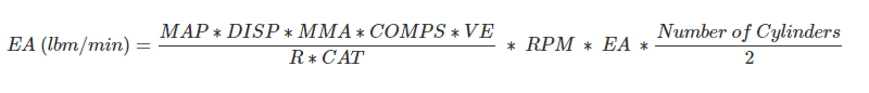 Image Added
...
...
| host | Confluence:6334724835 |
|---|
| alignment | left |
|---|
...
Estimated\ Airflow\ (lbm/min)=\frac{MAP * DISP * MMA * COMPS * VE}{R * CAT}\ *\ RPM\ *\ Estimated\ Aircharge\ * \frac{Number\ of\ Cylinders}{2}
| Anchor |
|---|
_Toc311462577 | _Toc311462577 | | Anchor |
|---|
__RefHeading__| Anchor |
|---|
| _Toc311462577 |
|---|
| _Toc311462577 |
|---|
|
| Anchor |
|---|
| __RefHeading__3666_178852463 |
|---|
| __RefHeading__3666_178852463 |
|---|
|
Ideal Gas Law – SD Reference CalculationsThe non-linear charge temp correction is inherent to the equation above in determining the estimated aircharge. However, it would be useful to be able to tweak the charge temp correction because our CAT sensor input may not always be exactly representative of actual charge temp. This is highly dependent on the placement of the CAT sensor for a given car.
...
First the ECU will calculate the estimated aircharge:
| Mathblock |
|---|
| host | Confluence:6334724835 |
|---|
| alignment | left |
|---|
|
Estimated\ Aircharge\ (lbm/event)=\frac{50.289 * 0.56525 * 0.063867917 * 0.8}{2.455257605 * 310.928} = 0.0019025207920206 |
Followed by the estimated airflow:
| Mathblock |
|---|
| host | Confluence:6334724835 |
|---|
| alignment | left |
|---|
|
Estimated\ Airflow\ (lbm/min)= 0.0019025207920206 * 3000 * 2 = 11.42 |
Additionally, we can estimate load at this point with the given aircharge by dividing against the SARCHG.
| Mathblock |
|---|
| host | Confluence:6334724835 |
|---|
| alignment | left |
|---|
|
Estimated\ Load\ (percent)=\frac{0.0019025207920206}{0.001526150} = 1.247 |
...
 Image Added
Followed by the estimated airflow:
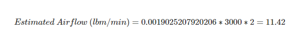 Image Added
Additionally, we can estimate load at this point with the given aircharge by dividing against the SARCHG.
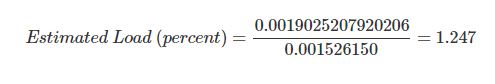 Image Added
| Anchor |
|---|
| _Toc311462578 |
|---|
| _Toc311462578 |
|---|
|
| Anchor |
|---|
| __RefHeading__3668_178852463 |
|---|
| __RefHeading__3668_178852463 |
|---|
|
SD Final AirchargeWe have calculated the SD reference aircharge, airflow, and load above. However, these calculations were only valid at our given reference temp of 100 degrees F. We must apply the MCT Pivot compensation which, with the default values in the tables, follows the ideal gas law the same as if we had originally plugged the current CAT value into the estimated mass airflow equation that was first described in this section. Let's assume that the current CAT is 122 degrees F. Looking at our MCT Pivot compensation table:
Image Removed
We see that the table calls for a multiplier of 0.96 (-4.00% correction at 122F MCT). From our reference example, we calculated a reference airflow of 11.42 lb/min. We apply the MCT Pivot correction from our table as follows:
If we were to plug in the CAT of 122F (50C) into the original equation given our current example:
MAP = 50.289 inHg (native units of the ECU, which is the same as 24.7psia)
RPM = 3000
VE = 0.8 (i.e.80%)
DISP = 2.261 liters (default for a 2.3L application)
SARCHG = 0.001526150 (Standardized Air Charge default for a 2.3L application)
MMA = 0.063867917 (L*inHg)/(K*Mol)
MCT = 323.15 Kelvin constant (our new temp of 122 F)
R = 2.455257605 (L*inhg)/(K*Mol) (using the inHg native ECU units for MAP)
So, lets do the math:
| Mathblock |
|---|
| host | Confluence:6334724835 |
|---|
| alignment | left |
|---|
|
Estimated\ Aircharge\ (lbm/event)=\frac{50.289 * 0.56525 * 0.063867917 * 0.8}{2.455257605 * 323.15} = 0.0018305647062397 |
| Mathblock |
|---|
| host | Confluence:6334724835 |
|---|
| alignment | left |
|---|
|
Estimated\ Airflow\ (lbm/min)= 0.0018305647062397 * 3000 * 2 = 10.98 |
...
| host | Confluence:6334724835 |
|---|
| alignment | left |
|---|
...
gas law the same as if we had originally plugged the current CAT value into the estimated mass airflow equation that was first described in this section. Let's assume that the current CAT is 122 degrees F. Looking at our MCT Pivot compensation table:
Image Added
We see that the table calls for a multiplier of 0.96 (-4.00% correction at 122F MCT). From our reference example, we calculated a reference airflow of 11.42 lb/min. We apply the MCT Pivot correction from our table as follows:
If we were to plug in the CAT of 122F (50C) into the original equation given our current example:
MAP = 50.289 inHg (native units of the ECU, which is the same as 24.7psia)
RPM = 3000
VE = 0.8 (i.e.80%)
DISP = 2.261 liters (default for a 2.3L application)
SARCHG = 0.001526150 (Standardized Air Charge default for a 2.3L application)
MMA = 0.063867917 (L*inHg)/(K*Mol)
MCT = 323.15 Kelvin constant (our new temp of 122 F)
R = 2.455257605 (L*inhg)/(K*Mol) (using the inHg native ECU units for MAP)
So, lets do the math:
 Image Added
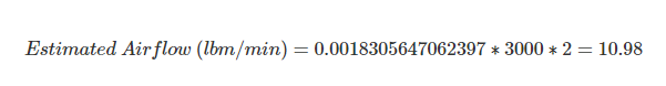 Image Added
We can now realize more complete accuracy in the calculations with these compensations applied. Note that in these examples the other compensations were assumed to be 1.0.
| Anchor |
|---|
| _Toc311462579 |
|---|
| _Toc311462579 |
|---|
|
| Anchor |
|---|
| __RefHeading__3670_178852463 |
|---|
| __RefHeading__3670_178852463 |
|---|
|
Estimated VE CalculationThe SD ECU has the (SD) Estimated VE (OEM) monitor which allows you to determine an estimate of VE based on the OEM speed density model. The math for estimating VE is simply solving for VE in the estimated airmass equation given above. We are using the airmass as determined by the OEM tables as an input to our estimated VE calculation. Also note that displacement is being represented by all cylinders during this calculation.
| Mathblock |
|---|
| host | Confluence:6334724835 |
|---|
| alignment | left |
|---|
|
VE\ (percent)=\frac{Aircharge\ * R * CAT * Number\ of\ Cylinders}{MAP * DISP(full) * MMA * COMPS} |
calculation.
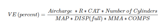 Image Added
Let's take the previous example and solve for VE given our previous estimated aircharge of 0.0018305647062397 lbm/event:
...
| host | Confluence:6334724835 |
|---|
| alignment | left |
|---|
...
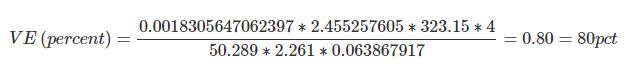 Image Added
As you can see, we end up with the same VE calculation as used in the original example.