
Accessport
User Guide
Nissan GT-R
MY 2008+| Table of Contents | ||||
|---|---|---|---|---|
|
Product Introduction
Congratulations on the purchase of the Accessport hand held programmer. The Accessport is the industry leading OEM ECU flashing, managing, and monitoring assistant. Unlock power hidden within the ECU by replacing conservative factory settings with more aggressive calibrations. The result is impressive gains in torque and horsepower while maintaining a high degree of safety. The Accessport can:
- Reprogram the factory engine control unit (ECU) with improved tuning parameters through the on-board diagnostic (OBD-II) port
- *Reprogram the factory transmission control module (TCM) with improved tuning parameters through the on-board diagnostic (OBD-II) port
- Monitor and log vehicle sensor data using on-screen digital gauges
- Read and clear engine diagnostic trouble codes (DTCs)
- Measure 0-60mph, ¼ mile times
- *Transmission clutch gear learning
- *Transmission touch point adjustment & clutch capacities
- Tire Pressure Monitor System (TPMS) Learning
- Bank Air Learn to rebalance the airflow between the left and right intakes.
*Available for AP3-NIS-006 and AP3-NIS-008 only.
Supported Part Numbers
- AP3-NIS-005
- AP3-NIS-006
- AP3-NIS-007
- AP3-NIS-008
Supported Vehicle List
- 2009 – 2016 Nissan ADM GT-R
- 2009 – 2016 Nissan East Asia GT-R
- 2009 – 2016 Nissan EDM GT-R
- 2009 – 2016 Nissan Gulf Spec GT-R
- 2008 – 2016 Nissan JDM GT-R
- 2009 – 2016 Nissan South Africa GT-R
- 2009 – 2018 Nissan USDM GT-R
Supported Transmission List (AP3-NIS-006 only)
- GT-R Transmission LC1 JF02A
- GT-R Transmission LC1 JF04A
- GT-R Transmission LC1 JF07A
- GT-R Transmission LC1 JF07C
- GT-R Transmission LC1 JF07D
- GT-R Transmission LC1 JF07E
- GT-R Transmission LC2 JF02B
- GT-R Transmission LC2 JF02E
- GT-R Transmission LC2 JF03B
- GT-R Transmission LC2 JF04A
- GT-R Transmission LC2 JF04B
- GT-R Transmission LC2 JF09A
- GT-R Transmission LC2 JF09D
- GT-R Transmission LC2 JF09E
- GT-R Transmission LC3 JW91A
- GT-R Transmission LC3 JW91B
- GT-R Transmission LC3 JW91C
- GT-R Transmission LC3 JW91D
- GT-R Transmission LC4 KB51A
- GT-R Transmission LC4 KB51B
- GT-R Transmission LC5 KJ10A
- GT-R Transmission LC5 KJ10B
- GT-R Transmission LC5 38B0A
- GT-R Transmission LC5 38B0B
** Not all models will be supported at initial release
Supported Transmission List (AP3-NIS-008 only)
- GT-R Transmission LC1 62B1A
- GT-R Transmission LC1 62B1B
- GT-R Transmission LC2 89S0B
- GT-R Transmission Gen. 2 LC3 80B0A
- GT-R Transmission Gen. 2 LC3 80B0B
- GT-R Transmission Gen. 4 LC4 6AV0A
In-Box Contents

WARNING! |
|---|
| Installation and use of the Accessport may void all or a portion of the vehicle manufacturer's standard warranty. There is no guarantee expressed or implied by COBB Tuning or any of its affiliates for the use of the Accessport. The user accepts all risks and responsibilities when using the Accessport. |
| WARNING! |
|---|
| Use of the Accessport while operating a moving vehicle is strictly prohibited by law. COBB Tuning and its affiliates accept no responsibility for damages or injury caused by misuse of the Accessport. |
| WARNING! |
|---|
| The Accessport may not be able to function if the vehicle's wiring has been modified. If problems occur while using the Accessport, please verify that all wiring to and from the ECU is correct and functional. |
Accessport Installation:
What Is A Map?
The Accessport reprograms the factory tuning parameters inside the engine control unit (ECU) using map files, which contain specially written instructions for the Accessport to follow during the reprogramming process. A map file can contain information for any number of different modifications or enhancements to a vehicle, ranging from a race map for heavily modified vehicles, to an economy map for a stock vehicle. Through the use of the Accessport and different map files the ECU can be reprogrammed to accommodate virtually any vehicle configuration.
Mounting Options
A universal 'sticky' mount is included with the Accessport. For the best results, we recommend installing the mount vertically, and preparing the mounting surface with the included alcohol wipe.
- NOTE: It's important to note that not all surfaces provide a strong adhesive bond.
- NOTE: The Accessport cradle is compatible with "Dual T" style mounts.
Pre-Installation
The Accessport comes with the most up-to-date software and map files available at the time of shipment. However, it is possible that updated software and/or map files have been made available since the time of shipment. Therefore, the recommended procedure is to connect the Accessport to the AP Manager software and download the latest firmware for the target vehicle. Please visit www.cobbtuning.com/apmanager to download AP Manager and to find a link for the AP Manager manual.
If you have issues transferring maps or updating the Accessport while using USB 3.0 ports, please try using a USB 2.0 hub adapter.
- NOTE: The Accessport is preloaded with a default set of maps for all cars that it supports. This may include but is not limited to Stage1, Stage2, Stage3 (all octanes), Anti-theft, Economy, and Valet. If you would like to view all maps available you can visit the Maps section of our website.
| IMPORTANT! |
|---|
For installation purposes, it is important to ensure that the vehicle's battery has adequate power for both the Accessport and the ECU. Because of this, it is recommended that all in-car electronics and vehicle lights are turned off during the installation process to reduce drain on the vehicle's battery. For improved safety during installation, a car battery charger can be connected to the vehicle during the installation process. |
Screen Capture
Screenshots can be captured by holding down the [CANCEL] button for two seconds. Any stored screen captures can be retrieved by using Accessport Manager.
Getting Started
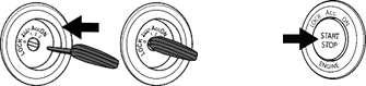
1. You will need the Accessport and OBD-II cable to perform the installation. Insert the key into the vehicle’s ignition and leave it in the OFF position. For keyless cars, make sure the vehicle is in the OFF state.
2. Locate the vehicle's OBD-II port. Location of the OBD-II port may vary depending on the vehicle model.
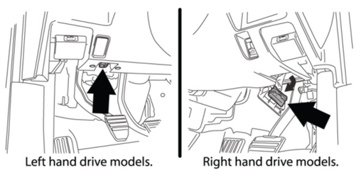
3. Connect device to the OBD-II port. Plug the OBD-II cable into the OBD-II port under the dash of vehicle. Then connect the small end of the OBD-II cable to the port on the bottom of the Accessport.
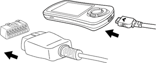
4. Make sure the clasp on the OBD-II cable firmly engages with the port.

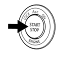
5. Press the START/STOP button twice with your foot OFF the brake pedal to turn on the ignition, but do not start the vehicle.
NOTE: The engine should not be running.
6. Select [Install] from the Accessport menu by pressing the [OK] button to proceed with installation.
Accessport Buttons:
Standard Tuning vs SD (Speed Density) Tuning
Standard Tuning uses MAF (Mass Air Flow) sensor for air flow calculations. COBB Tuning provides Off-The-Shelf (OTS) maps created using this calculation method.
SD (Speed Density) Tuning uses MAP (Manifold Absolute Pressure) sensor for air flow calculations. Users who prefer the vehicle to be tuned by this method must either have the vehicle professionally tuned. The Accessport will not be pre-loaded with Speed Density maps.
Vehicle Identification
The Accessport will attempt to automatically determine the target vehicle for installation. Verify that the identified vehicle is correct and press [OK] to confirm.
If an error occurs:
Please refer to the Troubleshooting Section.
Map Selection
After the Accessport identifies the vehicle, it will present a list of maps. Maps that are not intended for the identified vehicle are displayed in gray. The Accessport will reprogram the ECU with the calibration data from the map selected for installation; this will become the base data for the ECU. To ensure the best performance, select the map that most closely matches the modification level of the vehicle.
If you are unsure about which map applies to your modification level, please visit the Maps section of the website and reference the map notes. You can find the map notes for each of our maps by clicking on your vehicle and choosing your intake type. The map notes will list the modification requirements for each map, average power gains, boost targets, along with other useful information.
Select a map and press [OK] to proceed with the installation. If you wish to see a longer description for the highlighted map, press and hold the [OK] button on the desired map. After reading the description, you can press [CANCEL] to go back to the map list or press [OK] to select that map and proceed with the installation.
What Is A Map?
The Accessport has the capability to reprogram the factory tuning parameters inside the engine control unit (ECU) and transmission control module (TCM) using map files. Map files contain specially written instructions for the Accessport to follow during the reprogramming process. A map file can contain information for any number of different modifications or enhancements to a vehicle, ranging from a race map for heavily modified vehicles, to an economy map for a stock vehicle. Through the use of the Accessport and different map files the ECU can be reprogrammed to accommodate virtually any vehicle configuration.
Save Stock ECU/TCM Program Data
After confirming the map to be installed, the Accessport will download the current stock ECU/TCM data from the vehicle. The Accessport saves this data for use during the uninstall process to ensure that the vehicle is completely returned to stock. The download process will take a few minutes to complete.
| WARNING! |
|---|
If a previous installation of an Accessport is detected, you will be given the option to overwrite it with a new installation. Be aware that the previous installation will be permanently lost and unrecoverable. In the case of a previous install, a stock ECU program supplied on the Accessport will be used when you uninstall. |
Install Accessport Programming
With the stock ECU data saved, the Accessport will automatically proceed with installation to the vehicle. At this point, the Accessport reprograms the vehicle's ECU with new program data and calibration parameters from the installation map file. This process will take several minutes to complete.
| WARNING! |
|---|
| Do not disturb the Accessport and the OBD-II connector while installation is taking place. Failure to do so may result in incomplete ECU reprogramming which will render the vehicle inoperable. If an error occurs during the reflash, the Accessport will enter Recovery Mode and attempt to recover the reflash. |
Transmission Control Module (TCM) Flashing
TCM flashing is available on AP3-NIS-006 and AP3-NIS-008 part numbers. Once "Install to TCM" is selected, follow the instruction to save stock TCM program data; it takes approximately 7 minutes to complete the operation. Press OK to continue with saving the stock data, or press CANCEL to skip the process.
After the Accessport downloads and saves the stock TCM program data, it will proceed with installation of TCM data to the vehicle. Choose from a list of TCM map options.
| WARNING! |
|---|
| Do not disturb the Accessport and the OBD-II connector while installation is taking place. Failure to do so may result in incomplete TCM reprogramming which will render the vehicle inoperable. If an error occurs during the reflash, the Accessport will enter Recovery Mode and attempt to recover the reflash. |
Installation Complete
Follow all on-screen prompts on the Accessport to complete the installation process. The Accessport is now fully installed and ready for use and the vehicle's ECU and TCM, if applicable, are now programmed with new calibration data. The Accessport does not need to be plugged into the vehicle for the calibration to be in effect. You can disconnect the Accessport at this time or leave it plugged in to use any of the many features outlined below.
Please note that the Accessport is designed to work with only one vehicle at a time. Once the Accessport is installed, it cannot be used with another vehicle until it is uninstalled from the original vehicle.
Accessport Features & Functionality

Gauges
The Accessport can read sensor data from the factory ECU and display it as an on-screen gauge. This feature allows the Accessport to function as an auxiliary gauge displaying boost, RPM, temperature, or any number of other parameters available in the factory ECU.
The Accessport can also record sensor data from the factory ECU while you drive. With the ability to store multiple sessions, the Accessport can function as a complete engine datalogger and diagnostic tool. To begin datalogging, press the [OK] button while in the Gauges function. While the Accessport is recording a datalog, a single light blue light will scroll in the shift light. To view the results of your datalog sessions, simply connect the Accessport to your PC and retrieve the results using the AP Manager software. Data Log recordings are stored in a .csv (Comma Separated Values) format and are easily viewed using any spreadsheet application.
When you first select the Gauges function, you will be prompted to select an initial gauge layout. This layout can be changed at any time from the Change Gauge Layout menu.
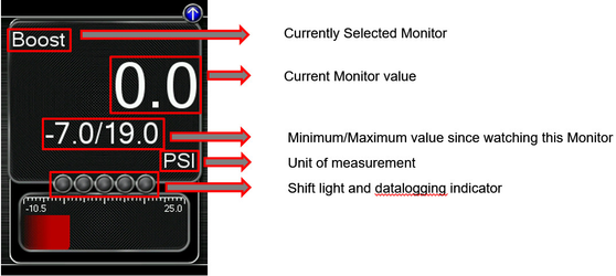
Press the [Up] or [Down] button to bring up the header. Then press the [Down] button to highlight the monitor you would like to interact with and press [OK]. You will then be presented with the following options.
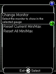
Change Monitor – Select the monitor that will be shown in the selected gauge
Note: While in the Change Monitor list, you can press [UP] to find a Sort Monitors option. This option will sort all monitors in reverse alphabetical order.
Reset Current Min/Max – Reset the minimum and maximum values of the selected gauge
Reset All Min/Max – Reset the minimum and maximum values of all gauges
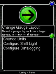
Change Gauge Layout – Select a gauge layout from a single large gauge, to many small gauges
Change Units – Set the unit scheme
Configure Shift Light – Adjust the RPM of the Shift Light
Configure Datalogging – Select which monitors to datalog
You have the ability to display between 1 – 6 gauges in different preset formats. The formats are as follows:
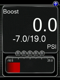
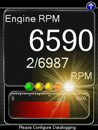
One Gauge
- One large Digital Gauge w/ Bar Gauge
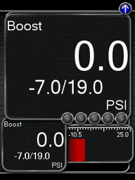
Two Gauges
- One large Digital Gauge
- One small Digital Gauge w/ Bar Gauge
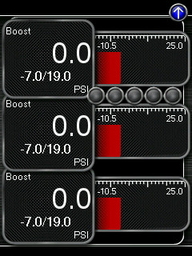
Three Gauges
- Three small Digital Gauges w/ Bar Gauges
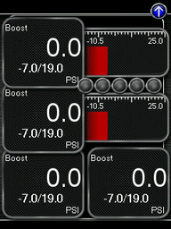
Four Gauges
- Two small Digital Gauges w/ Bar Gauges
- two small Digital Gauges
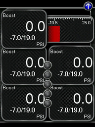
Five Gauges
- One small Digital Gauge w/ Bar Gauge
- four small Digital Gauges
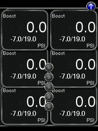
Six Gauges
- Six small Digital Gauges
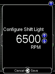
Configure Shift Light
![]()
Press [OK] and using the [Up] and [Down] buttons, set the RPM to the desired level to have the shift light flash. Press [OK] to save the RPM you have selected. By default, the shift light RPM is set above the stock redline. This essentially disables the shift light since that RPM will not be reached. You will need to lower the shift light RPM to enable this feature.
Press [UP] to find the Setup option for the Shift Light, where you will find the following options:
Disable Shift Light – Disables the shift light function and removes the shift light from the gauges screen.
- NOTE: When you initiate a datalog, the shift light will reappear to notify you that you are logging.
Reset Shift Light – Resets the shift light back to the default value.
Configure Datalogging
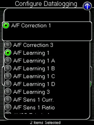
This list allows the user to enable or disable parameters for logging. Only monitors with a green circle will be recorded while using the datalogging feature. There is a default log list that includes a group of monitors put together by our in-house tuners. You can make changes to the log list by highlighting a monitor and pressing the [OK] button to activate/deactivate it for logging. Pressing the [Cancel] button will save any changes you have made to the datalog list.
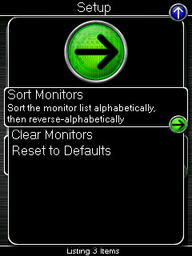
Press [UP] to find the Setup option for Configure Datalog where you will find the following options:
Sort Monitors – Sort the monitor list alphabetically, then reverse-alphabetically
Clear Monitors – Clear all monitors from the datalog list
Reset to Defaults – Restore the datalog list to the default list
NOTE: You will be notified if you have exceeded the recommended amount of monitors to record in one datalog. If you receive this prompt, reduce the amount of monitors you are recording.
NOTE: The Accessport is only capable of datalogging while the ignition is turned to the ON position. The Accessport will display an error message if it cannot communicate with the vehicle.
NOTE: Up to 10 log files can be stored on the Accessport. Use AP Manager to delete unneeded logs. If datalogging is started when there are already 10 log files on the Accessport, the log file with the lowest numerical value will be automatically overwritten.
NOTE: The 10 log files can be a combined length of 2+ hours long.

The Accessport can calculate several performance measurements.
NOTE: The Accessport is only capable of calculating performance test results while the ignition is turned to the "ON" position. The Accessport will display an error message if it cannot communicate with the vehicle.
0-60 MPH
To record the 0-60 MPH performance, select this menu option and follow instructions. A time slip showing the performance results will be displayed at the end of the performance test.
¼ Mile
To record the ¼ Mile performance, select this menu option and follow instructions. A time slip showing the performance results will be displayed at the end of the performance test.
Press [UP] to find the Setup option for Performance where you will find the option to Change Units.
Change Units
Imperial – This unit scheme uses imperial units: F, mph, PSI, AFR
Metric w/ AFR – This unit scheme uses metric units (excl. AFR): C, kph, kPA, AFR
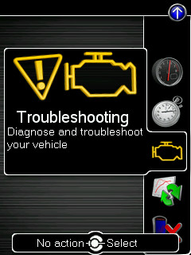
Troubleshooting

Use the Accessport as a diagnostic tool.
NOTE: The Accessport is only capable of communicating with the ECU while the ignition is turned to the "ON" position. The Accessport will display an error message if it cannot communicate with the vehicle.
Bank Air Learn (Non-SD Only)
Relearn and rebalance airflow between the left and right intake manifolds. For more information on Bank Air Learn functions, please refer to How To: Perform Bank Balance on GTR.
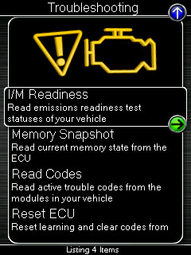
Memory Snapshot
Use this feature to save a snapshot of the current ECU memory state. This function is primarily for use by Tech Support for troubleshooting purposes. To take a Memory Snapshot, select Troubleshooting from the main menu. Then, scroll to “Memory Snapshot” and press the center button. You will then see the status bar. When this gets to 100%, the Snapshot is complete. You can then use AP Manager to transfer the file to your computer.
Memory Snapshot TCM
Use this feature to save a snapshot of the current TCM memory state. This function is primarily for use by Tech Support for troubleshooting purposes. To take a Memory Snapshot, select Troubleshooting from the main menu. Then, scroll to “Memory Snapshot” and press the center button. You will then see the status bar. When this gets to 100%, the Snapshot is complete. You can then use AP Manager to transfer the file to your computer.
Read Codes
Use this function to read trouble codes from the engine computer. Stored codes indicate a mechanical or electrical fault. Use the up/down buttons to highlight a code and display a short description of the trouble code (if available).
Reset ECU
Reset learning and clear codes from the ECU
NOTE: Just like pulling the negative battery terminal to reset the ECU, this will clear out any stored compensations and optimizations made by the ECU (such as long term fuel trims).
Identify Vehicle
Identifies the year, make, and model of your vehicle.
- For more details see - How To Identify Vehicle Rom Using an Accessport
TCM Service (AP3-NIS-006 and AP3-NIS-008 only)
Contains Clutch Gear Learn and Touch Point Adjust functions. For more information on TCM Service functions, please refer to TCM Adjustments.
TPMS Learning
TPMS Learning is used to register new TPMS sensors. For more information on TPMS Learning, please refer to TPMS Learning.
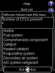
I/M Readiness
Use this feature to read Inspection / Maintenance (I/M) test statuses of your vehicle. To read I/M, Select Troubleshooting from the main menu. Then, scroll to I/M Readiness. You will see an extensive list of readiness monitors.
Tune

Enhance the performance of your car.
Adjust LC RPM (AP3-NIS-006 and AP3-NIS-008 only)
This option can be found in the Available Adjustments menu and allows the Launch Control RPM to be adjusted. In order to use this feature, you must use a map created using Accesstuner v1.9.1.0-8151 (or newer). Simply opening your existing maps and re-saving them with this version of Accesstuner will suffice. To adjust Launch Control RPM, enter the Tune menu, select “Available Adjustments”, then select “Adjust LC RPM”. Press the OK button, then use the UP/DOWN arrows to raise or lower the LC RPM in increments of 100; press OK again to save your setting.
NOTE: Changing your ECU map or switching to a different map slot will reset your launch control RPM to the default settings.
NOTE: User adjustable Launch Control currently only supports LC4 and LC5.
Switch Traction Control
This option can be found in the Additional Adjustments menu and allows you to switch between a predetermined amount of slip. Traction Control adjustments are disabled by default and requires custom tuning via Accesstuner.
Change Map
To change the mapping on your ECU, select this menu option and follow the instructions. The ignition must be turned to the “ON” position during the Change Map operation. You will be prompted to select a pre-loaded map. The same warning that applies to the installation process applies here as well (battery charge level, turn accessories off, climate control turned off, etc.)
NOTE: If you wish to see a longer description for the highlighted map, press and hold the [OK] button on the desired map.
Change TCM Map (AP3-NIS-006 and AP3-NIS-008 only)
To change the mapping on your TCM, select this menu option and follow the instructions. The ignition must be turned to the “ON” position during the Change Map operation. You will be prompted to select a pre-loaded map. The same warning that applies to the installation process applies here as well (battery charge level, climate control turned off, turn accessories off, etc.)
TCM Adjustments (AP3-NIS-006 and AP3-NIS-008 only)Anchor TCMADJUSTMENTS TCMADJUSTMENTS
There are two TCM tools that are included in the AP3-NIS-006 and AP3-NIS-008 firmware.
- Run Clutch Gear Learning: This will run the gear learning for the transmission. To use this option the car and transmission fluid must be warmed up to at least 81 degrees Celsius. When running the transmission gear learning the transmission must be in Park and the engine at idle. The Clutch Gear learning is performed during any regular maintenance and when the TCM or transmission is replaced.
NOTE: Clutch gear learning can only be performed once in a drive cycle (the ignition switch ON->OFF->ON).
NOTE: If clutch gear learning can't be performed, turn the car off and then back on, and then perform the clutch gear learning again.
- Touch Point Adjust: This option in the Accessport will walk you through the process of setting the touch point values. The range for the touch points is -7 to +7. The factory sets the values all to 0. Touch point for each clutch is learned during the transmission learning process and trimmed/modified by the adjustments via the Accessport. The touch point is the point where the clutch starts to engage. This is used during accelerating from a stop. The capacitor alters the clamping force especially when it is fully engaged at full throttle.
- Clutch Torque Capacities:
- 0: Initial setting
- +1 to +7: Clutch capacity up
- -1 to -7: Clutch capacity down
If a shock or slip is large during gear shift and start-up, adjust the clutch capacity.
* Higher horsepower GT-Rs can eliminate unwanted clutch slip with a +2 or +3 level of Clutch Capacity.
Clutch Touch Points:
- 0: Initial setting
- +1 to +7: Move the clutch touch point closer
- -1 to -7: Move the clutch touch point farther
In the event of strong creep power, poor start-up response, or excessive start-up shock, adjust the clutch touch point.
| Anchor | ||||
|---|---|---|---|---|
|
TPMS Learning is used to register new TPMS sensors, either from replacing existing sensors or new wheels. To use TPMS Learning you must have a TPMS registration tool that is compatible with the GTR.
For testing purposes we used: KTI-71999 from http://www.ktoolinternational.com/
TPMS Learning Process:
- Turn key position to “On”.
- Connect the Accessport to your vehicle’s OBD port and select “Tune.” Then go to “TPMS Learning.”
- A prompt will appear with instructions on how to successfully program the vehicle’s TPM sensors. Press “OK” to get the process started.
- After completing step 2 exit the vehicle with the Tire Pressure Positioning Sensor Tool. Start with the front driver side tire (front passenger for RHD cars). Point the rounded end of the device at the sensor through the tire (the sensor is located behind the tire on the valve stem). Then push the “Activation” button until the device beeps. The appropriate light should come on (315MHz for US and 434MHz for EU) notifying the sensor is set.
- Verify the Accessport registered the tool’s activation of the sensor. This can be confirmed by checking if the Accessport says “OK!” next to the TPM sensor just programmed on its screen.
- Repeat steps 3 and 4 for each tire working your way around the vehicle in a clockwise motion. It is important to note that the TPMS learning feature cannot be exited after starting. It will timeout after 3 minutes. If it does timeout during programming, the process will need to be restarted. The 3 minute timeout will reset after each sensor is registered to prevent any unwanted timeouts.
- Once the final sensor is registered the process is complete. There may be variances in the amount of time pressure is actually displayed due to different TPM sensors. If readings are not instantly displayed on the GT-R gauges, some users may have to drive a few minutes before pressures are identified.
Restore OTS Map
Select this option to Restore COBB Off-The-Shelf Maps that have been deleted from the Accessport.
Show Current Map
To see the last map that was flashed to your car, select this menu option. You can press the [OK] button to see a detailed description of the map.
- ECU Reflash: Last map loaded via “Change ECU Map” option during Change Map.
- TCM Reflash: Last map loaded via “Change TCM Map” option during Change Map.
Uninstall

Selecting this option will remove the Accessport programming from the vehicle on which it is installed and return the ECU/TCM back to a stock state. It is highly recommended to uninstall the Accessport prior to taking your car to the dealer for any type of service. It is also crucial that you uninstall your Accessport if you plan on selling your vehicle or Accessport separately. Otherwise the Accessport will be locked to your vehicle and cannot be used on another car.
Setup
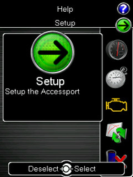
To enter the Setup function, press the [Up] button to bring up the header above the Gauges icon. From here you will have access to the following options:
Auto On/Off Settings – Enable this feature and your Accessport will power on and off with your vehicle.
- Enable Auto On/Off – This will enable the Auto On/Off Feature.
- Enable Diagnostic Logging – You may be instructed by a Customer Service Representative to enable this function when diagnosing issues.
- Enable Low Battery Shutdown – This will shut the Accessport down if battery voltage drops below 10v.
Change Language – Choose from an array of various languages (Note that not all menu entries are translated).
Change Units – Choose from Standard, Metric, and Metric with AFR.
Change Boost Wrap Units: Set the boost wrap unit scheme for your vehicle’s multi-function display.
NOTE: ECU must be reflashed before new boost wrap units will be used.
Reset to Defaults – Reset all user settings back to default.
Help
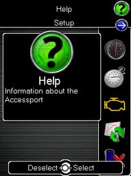
To enter the Help function, press the [Up] button to bring up the header above the Setup icon. From here you will have access to the following options:
About Accessport:
Displays technical information about the Accessport.
- Firmware
- Part Number
- Serial Number
- Installation State
- TCM Installation State
- Vehicle
Context Help: Shows more information about the screen you are currently viewing.
Button Help: Displays the button map.
Icon Help: Displays the various icons you will find on the Accessport.
Demo Mode: This function allows you to run through a mock installation and see all of the features of the Accessport without needing to be connected to a vehicle.
Recovery Mode

If an error occurs during a reflash the Accessport and ECU will enter recovery mode. By selecting this option the Accessport will recover itself to the last selected or installed map.
NOTE: For Recovery Mode to function correctly, you will need to ensure that whatever condition caused the initial failure of the reflash is resolved. For example, if your battery voltage dropped too low during the reflash, put a battery charger on the car before attempting to use Recovery Mode.
Accessport Troubleshooting Anchor Accessport Troubleshooting Accessport Troubleshooting
| Accessport Troubleshooting | |
| Accessport Troubleshooting |
Symptom | Troubleshooting Steps |
Accessport will not communicate with vehicle. |
|
Accessport cannot reflash ECU. |
|
Accessport cannot identify vehicle during installation. |
|
Technical Support Contact Information
Web | |
Phone | (866) 922-3059 |
Environmental Information
Operating and Storage Temperatures
The Accessport is designed to be operated at temperatures between 32° and 95° F (0° and 35° C) and with a relative humidity below 90%. Using the Accessport outside of these recommendations may result in damage.
The Accessport is thermally protected and will not function if the temperature reaches extremely high levels. If the Accessport is not booting up correctly or the screen does not show everything correctly, turn the device off and move it to a cooler environment temporarily.
When storing the Accessport, do so in a place where temperature is always between 0° and 115° F (-18° and 46° C) and a relative humidity below 90%.
Never store your Accessport in an area that receives direct sunlight.
Do Not Get Wet
Take care to prevent any liquids from coming in contact with the Accessport or any associated equipment.
If your Accessport or any associated equipment gets wet, professional repair may be required. In such cases, please contact Technical Support BEFORE attempting to the use the Accessport.
Handling and Storage
Your Accessport may be damaged by improper storage or handling. Be careful not to drop your Accessport or any associated parts.
Never store your Accessport in an area that experiences any noticeable levels of vibration, static electricity, heat shock, or excessive swings in relative humidity.
Do Not Attempt Repairs Yourself
Never attempt to open your Accessport or any associated equipment. Doing so puts the components at risk of damage from, but not limited to, static shock. No user-serviceable parts are inside. At no time will ANY authorized representative of COBB Tuning, Inc. ask you to open or mechanically/electronically alter the Accessport.
Opening the Accessport will void any and all warranties for the device and its operation.