
3C1750 - GTR CAN Gateway Fuel Pressure Monitoring Kit
2008 - 2018 Nissan GTR
Congratulations on your purchase of the COBB Tuning CAN Gateway Fuel Pressure Kit! The following instructions will assist you through the installation process. Please read them BEFORE beginning the install to familiarize yourself with the steps and tools needed. If you feel you cannot properly perform this installation, we HIGHLY recommend you take the vehicle to a qualified and experienced automotive technician.
IMPORTANT! Installing this kit will require custom tuning or utilizing an appropriate Stage Power Package map if you have a matching mechanical configuration. Please consult with COBB or an authorized ProTuner in your area if you have any questions!
Table of Contents
| Table of Contents |
|---|
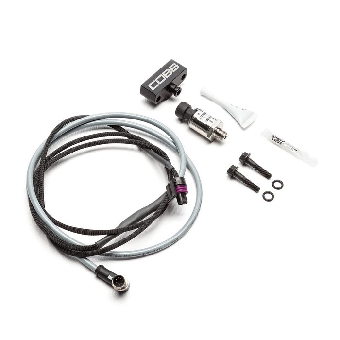
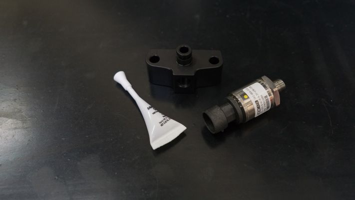
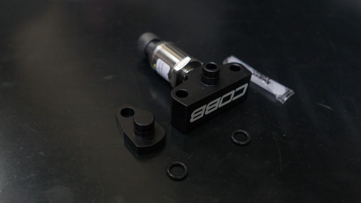
Parts List
Fuel pressure sensor
Fuel pressure sensor adapter
TIP sensor plug
CAN Fuel pressure harness
(2) M6x30mm bolts
(3) O-rings, only (2) are needed, 2mm wide, 7.5mm ID
Loctite (red)
Super lube (clear)
Tools Needed
Hand Tools
Wrenches
- 8mm Ratcheting combination wrench
- 10mm combination wrench
- 21mm combination wrench
- 22mm combination wrench
Install the COBB Fuel Pressure Sensor
- Park the car in a smooth flat area.
- Depressurize the fuel system by removing the gas cap and leave it off to remove any residual pressure in the fuel tank. It can also help to allow the car to sit for a short time in order for the residual pressure to slowly bleed down.
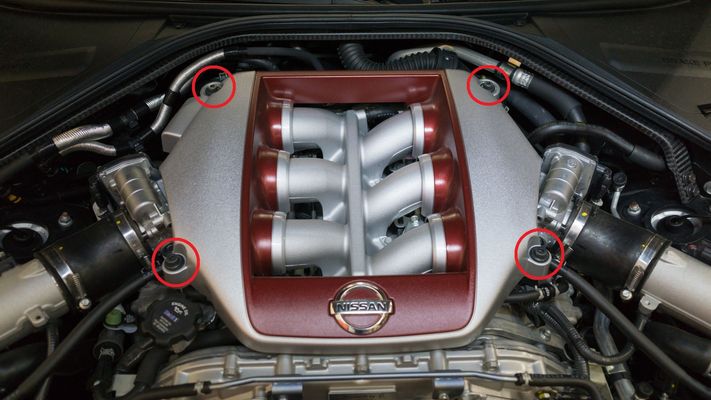
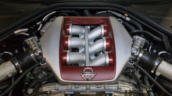
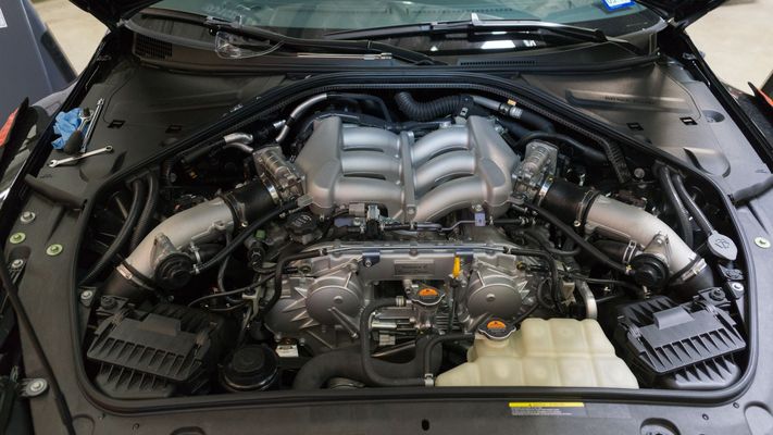
Remove the engine cover by removing the (4) bolts using an M5 Allen key

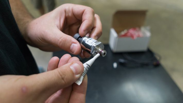
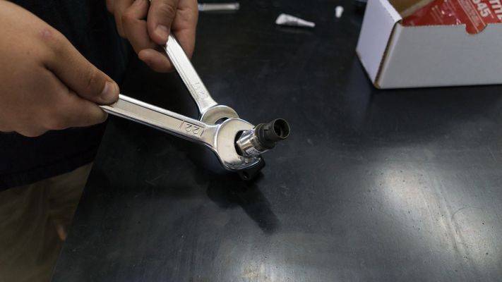
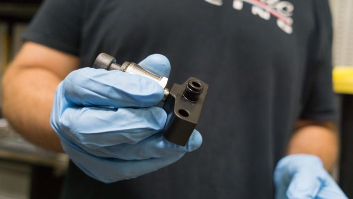
Attach the fuel pressure sensor to the fuel pressure sensor adapter using the included Loctite. You can use two open ended wrenches, 22mm or 7/8th wrench on the sensor and 21mm wrench on the adapter, to secure them together.
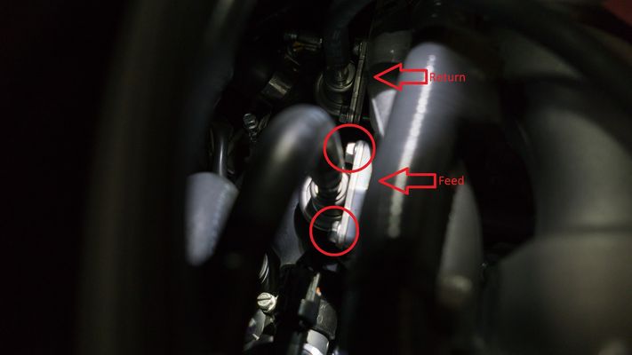
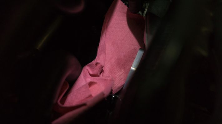
Place a rag under the fuel pressure damper on the feed side to catch any fuel that may leak and then remove the (2) bolts securing the fuel pressure damper to the feed side with a 10mm wrench.
Warning Eye Protection is recommended in order to reduce the possibility of getting fuel in your eyes.
Note The feed and return damper are identical, make certain you are removing the correct one. The feed side is closer to the passenger side of the vehicle.
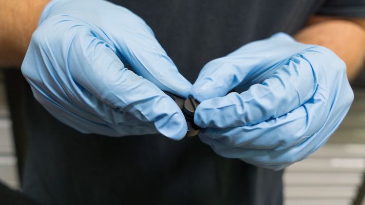
Install a lubed o-ring to the fuel pressure adapter.
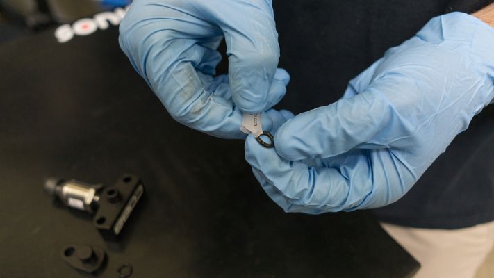
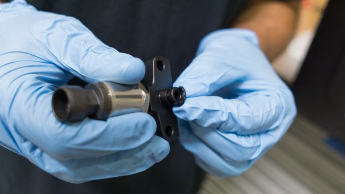
Install a lubed o-ring to the TIP sensor plug
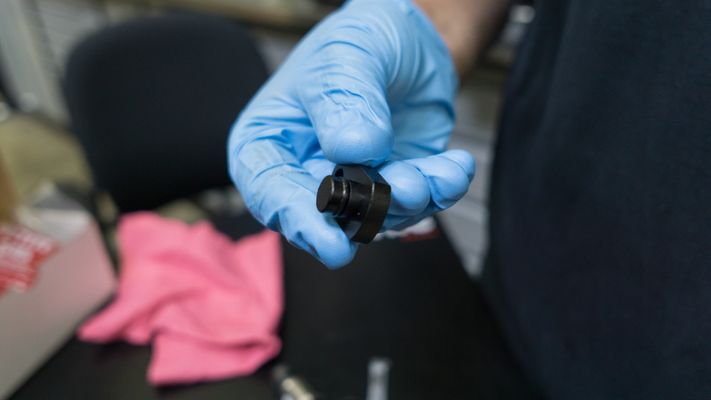
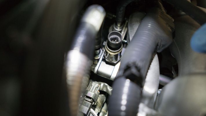
Install the assembled fuel pressure sensor adapter to the damper using the included (2) M6 bolts.

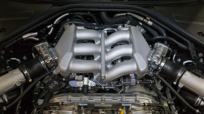
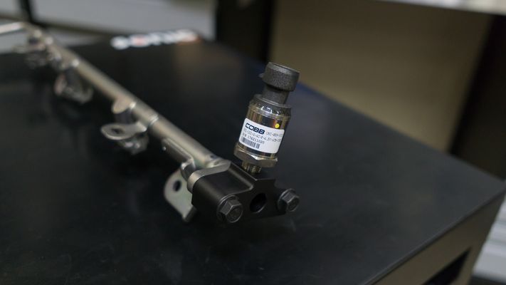
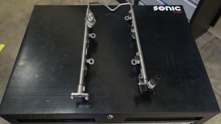
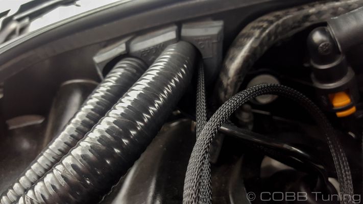
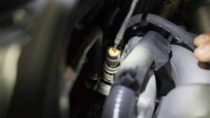
Reconnect the feed-side fuel line to the rail. Below are also pictures of the stock fuel rail outside the car so that you can see the intended final orientation with the fuel pressure sensor in the vertical position.
Stock Component Removal
- Park your car in a flat, level place and allow it to cool down completely.
- Remove the battery cover.
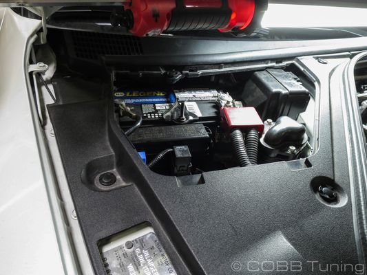
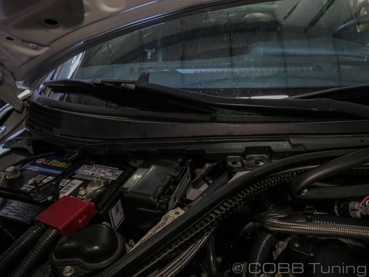
- Remove the sealing strip from along the top.
- Using your trim tool, pop out the 5 trim clips around the battery cover panel and remove it from the car.
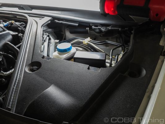
- Now remove the Brake booster cover along with the 5 trim clips on that cover.
- Remove the last two clips holding the battery cover section to the windshield and remove that component as well.
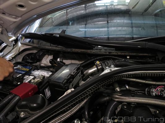
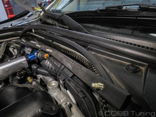
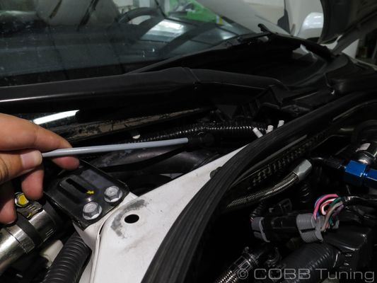
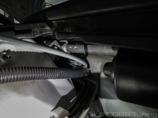
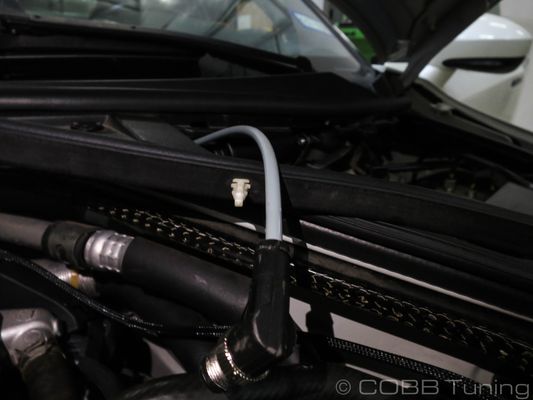
- Route the cable under the wiper cowling and over to the other side, making sure it doesn't get caught on anything.
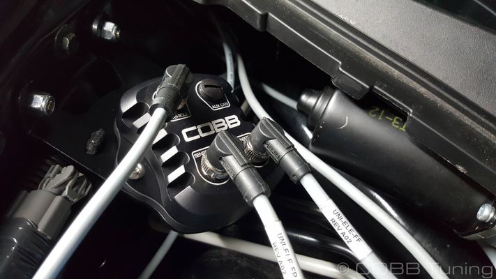
Screw down your gateway using the two provided 4mm Allen bolts and add the CAN signal harness to either of the sensor ports and screw it down firmly by hand.
Note These connectors are keyed and will not plug in to a port it is not designed for or if it is at the incorrect angle, so if it doesn't fit, don't force it, make sure you have the correct harness and that it is at the correct angle before screwing it down.
- Route your line out through the factory grommet and make sure it isn't rubbing on the metal.
- Plug the CAN harness into the fuel pressure sensor.

- Put the trim components back together after zip tying the harness up out of the way of moving objects.

- Flash an appropriate map that supports the CAN Fuel Pressure Sensor
- You're all done! Go out and enjoy!
Links
Nissan Calibration Map Notes for Nissan Vehicles
| Insert excerpt | ||||||
|---|---|---|---|---|---|---|
|