
715500 - Subaru Front Mount Intercooler Kit
2011 - 2014 WRX
2011 - 2014 STi
Congratulations on your purchase of the Subaru Front Mount Intercooler Kit STI 2011-2014. The following instructions will assist you through your installation process. Please read them first entirely BEFORE beginning the install and familiarize yourself with the steps and tools needed. If you feel that you cannot properly perform this installation, we HIGHLY recommend you take the vehicle to a qualified and experienced automotive technician.
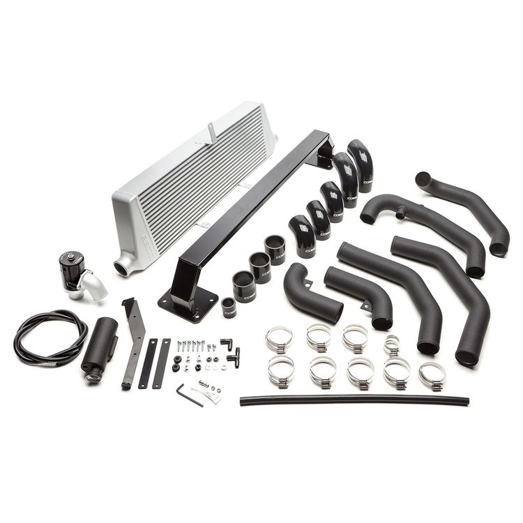
Part List
- Intercooler Core
- Bumper Beam
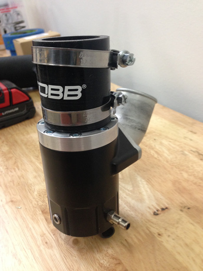
- Cobb Subaru Universal XLE BPV
- 2 x Long Silicone Elbow 2.5"
- 2 x Silicone Elbow 2.5"
- 2.5" - 2" Silicone Reducing Elbow
- 2.75" - 2.5" Silicone Reducer
- 2 x 2.5" Straight Silicone Coupler
- BPV Silicone Coupler
- 2ft 1/2" Silicone Vacuum Hose
- Upper Hot Pipe
- Mid Hot Pipe
- Lower Hot Pipe
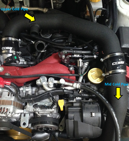
- Upper Cold Pipe
- Mid Cold Pipe
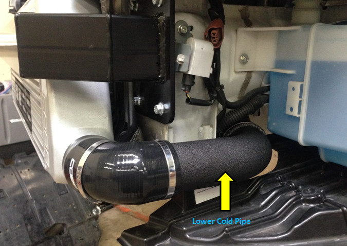
- Lower Cold Pipe
- Coolant Overflow Tank
- Coolant Overflow Tank Bracket
- Coolant Overflow Bracket Bottom Bung
- 5 x M6x25 Flange Head Bolt
- 3 x M6x12 Flange Head Bolt
- 2 x Lower Pipe Mounting Spacer
- 1/2"x1/2"x1/2" HDPE Black Tee
- 1/2"x1/2" HDPE Black Elbow
- 2 x GR Front Bumber Brace
- 2 x 5/8" Rubber Grommet
- 3/8" NPT Plug
- 2.75" Clamp
- 14 x 2.5" Clamp
- 2" Clamp
- 2 x BPV Clamp
- 2 x M6 x 18 Flat Washer
- 2 x M6 Serrated Flange Nut
- COBB Stencil
Tools Needed
- 7mm Socket
- 8mm Socket
- 10mm Socket
- 12mm Socket
- 3/8" Drive Ratchet
- Various length 3/8" Extensions
- Pliers
- Flat Blade Screwdriver
- Phillips Screwdriver
- Plastic Clip removal Tool
- Air Saw, rotary cutting tool, or utility knife
Parts required for Install
- Cobb SF Intake
Removal of Top Mount Intercooler
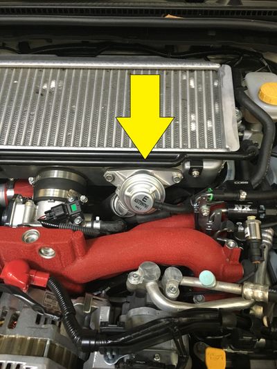
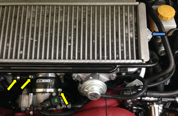
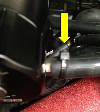
- Locate your stock bypass valve.
- Using a pair of pliers, remove the return line from the bypass valve.
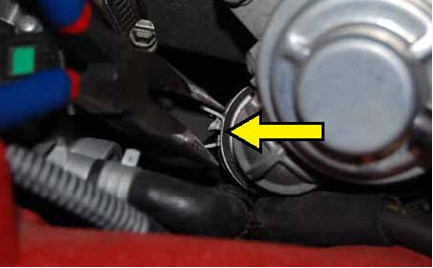
- Remove the vacuum line from the factory bypass valve.
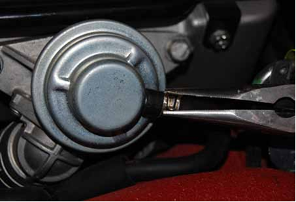
- Using a 12mm socket with ratchet, remove the 2 bolts that hold the bypass valve in place.
TIP: Make sure to keep an eye on the factory gasket behind the BPV. It can fall when you remove the valve and end up in difficult to reach locations! - Remove the bypass valve.
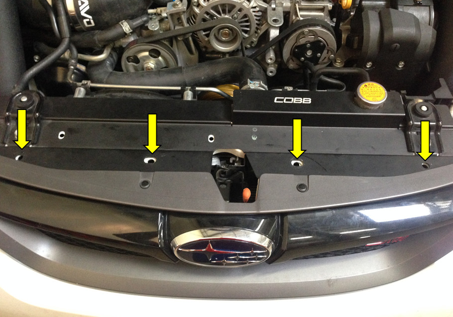
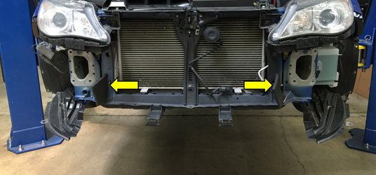
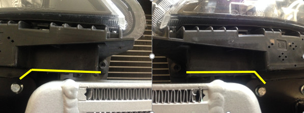
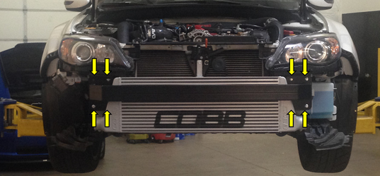
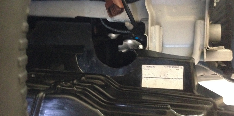
- Use a 7mm socket or flat blade screwdriver, loosen the clamps at the throttle body and turbo outlet (yellow arrows). Then with a 12mm socket and ratchet remove the bolts holding the stock intercooler (blue arrows) and remove the intercooler.
Removal of the Under Tray
- Raise the car up using on a lift or floor jack and jack stands to gain access to the underside of the car.
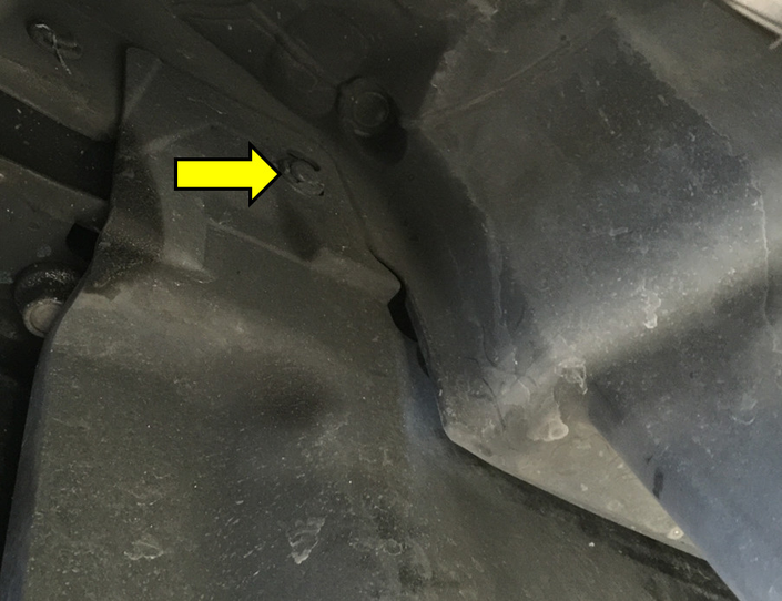
- Inside the drivers side wheel well there will be a clip holding the top of the plastic under-tray. Use a plastic clip removal tool or flat blade screwdriver to remove them. Repeat this procedure on the passenger side.
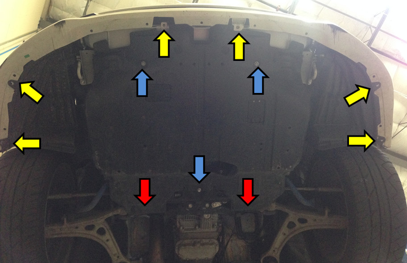
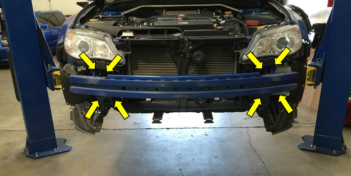
- From the bottom of the car, There will be 6 more clips to remove (two in the front and two on each side). Use a plastic clip removal tool or flat blade screwdriver to remove them. These are designated by the yellow arrows. Using a 12mm socket, remove the three bolts holding the bottom of the tray. These are designated by the blue arrows. Remove the final two clips by spreading and pulling them from the under-tray. These are designated by the red arrows. The under-tray can now be removed from the car.
Removal of Front Bumper
- Using a plastic clip removal tool or small flat blade screw driver, remove the 4 clips above the grill opening of the bumper.
- On the front of the drivers side wheel well, there will be 4 screw clips. Using a Phillips screwdriver, remove all 4 clips. It may be easier to access these with the wheel turned slightly. Repeat this procedure on the passenger side.
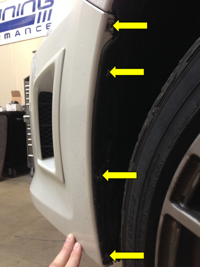
- With all the clips removed, gently pull on the top of both sides of the bumper cover where it meets the front fender. The bumper cover will detach from the car and can be removed by pulling it forward and away. If equipped, you will need to disconnect the fog lights via the connector plugs before fully removing the bumper cover.
TIP: It may be helpful to have an extra set of hands at this point to reduce the risk of scratching the bumper cover and/or bending the mounting clips.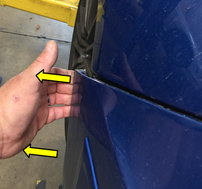
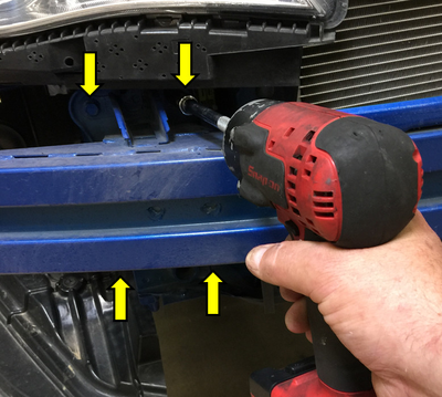
- In order to remove the bumper beam, loosen the eight mounting bolts with a 12mm socket and ratchet/impact. There will be 4 bolts on each side.
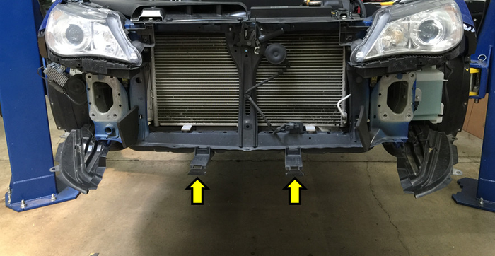
- Now remove the two lower bumper cover braces from the bottom of the core support with a 10mm socket and ratchet.
Removal/ Installation of Coolant Overflow Reservoir
The factory overflow tank will need to be removed and replaced with the Cobb Tuning low profile coolant overflow tank. This will provide adequate clearance for the cold side piping.
- Remove the coolant overflow line from the top of the tank.
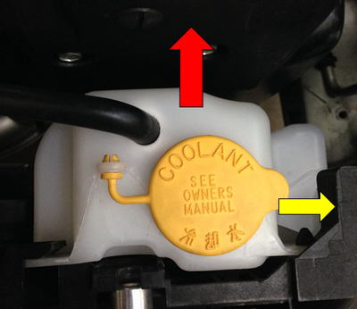
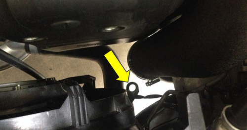
- Now press on the black tab on the right side of the radiator shroud (yellow arrow) to release the reservoir from the shroud. Push the reservoir towards the engine (red arrow.) Now lift upward to remove it from the car.
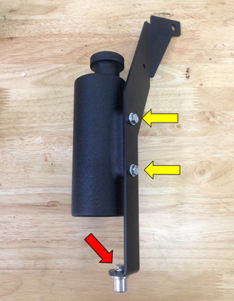
- It's now time to assemble the new coolant reservoir. Bolt the reservoir to the bracket with the M6x12 flange heads bolts provided (yellow arrows.) Bolt the coolant overflow bracket bottom bung to the bracket using an M6x12 flange head bolt (red arrow.) Tighten all the bolts with a 10mm socket or wrench. Make sure that the reservoir is bolted to the correct side of the bracket.
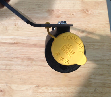
- Remove the reservoir cap from the factory overflow tank and install it on the new tank.
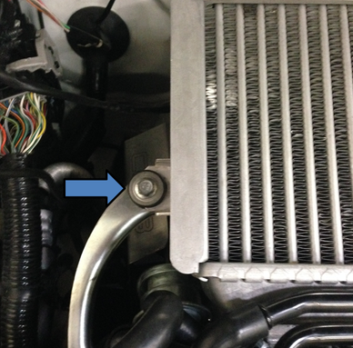
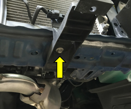
- To install the tank in the car, place the bottom bung of the bracket into the mounting hole on the radiator shroud. Bolt the top of the bracket to the radiator using the provided M6x25 flange head bolt. Make sure to install the 1/4"x3/4" spacer between the bracket and radiator. Tighten the bolt with a 10mm socket or wrench.

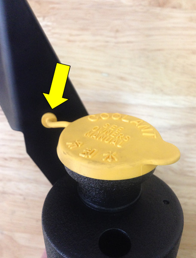
- Now slide the tube back into the top of the overflow tank. The end of the tube should be about 1/4" away from the bottom of the tank. Fill the reservoir approximately half full with coolant.
Trimming For the Front Mount Core - Core Support
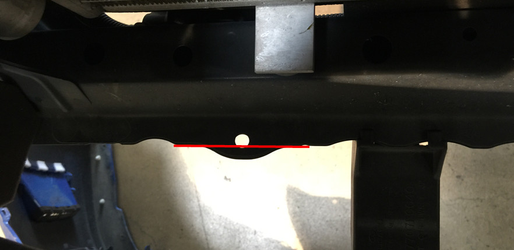
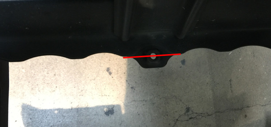
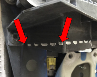
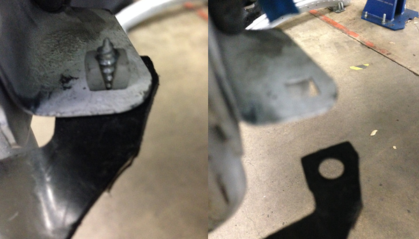
- With the removal of all factory components complete, it is now time to carefully trim some components to provide clearance for the intercooler core and piping. When looking down at the core support from the front of the car there are two tabs that stick out further than the rest. These will either need to be bent up or cut off to provide clearance for the core. Either method is acceptable. Check for clearance by holding up a straight edge along with bottom of the core support to ensure that these two tabs do not stick out further than the rest of the ridges.

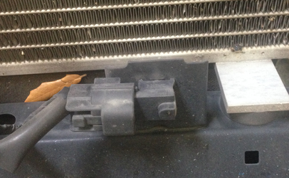
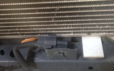
- Next, locate the ambient temp sensor on the drivers side of the bottom of the core support. Using a pair of pliers, gently remove the sensor and re-install it on the back side of the bracket.
Remove the two foam pads from the sides of the core support with a plastic clip removal tool.
Trimming For the Front Mount Core - Headlights
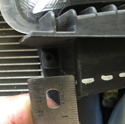
- The bottom of the headlight assemblies will also need to be trimmed to make room for the front mount core. Looking at the lower inner corner of the headlight from the front of the car, mark 1/2" up from the bottom corner (yellow arrow) and draw a straight line over 2.5" to the next corner (yellow line.)
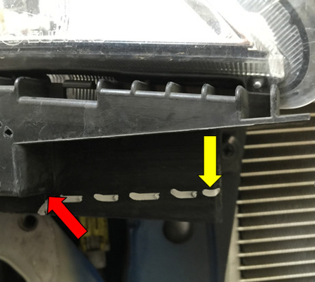
- From the side, continue the line from the to the rear corner of the light (red arrows).
- Using an air saw, die grinder, utility knife, etc cut off the marked area. After installing the core in the next step, double check for clearance to make sure the lights don't interfere with the intercooler core.
Installation of Intercooler Core
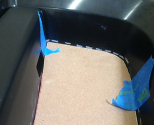
- If desired, use the provided template to paint "COBB" onto the front of your core as seen below. Make sure to mask off the surrounding areas around the template to prevent any over-spray.
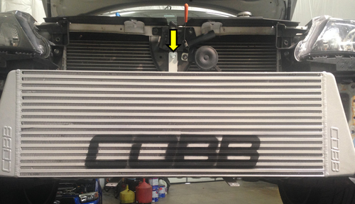
- Remove the bolt holding the hood latch to the center core support using a 12mm socket and ratchet. Install the intercooler and hand tighten the bolt.
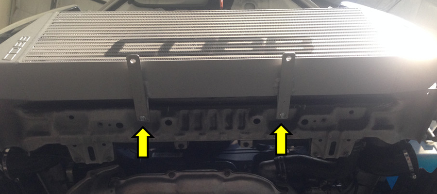
- Install the front bumper braces on the bottom of the intercooler. Do this by holding the front bumper braces in position and hand tightening the supplied M6x25mm flange bolts to capture both the bottom intercooler bracket as well as the front bumper brace. Leave the bolts a little loose to tighten later.
- Install the replacement bumper beam by holding the beam in position and fastening it with the factory bolts.
Modifying Inner Fender Liners and Under Tray
With the intercooler now in place, it's time to mock up the lower hot and cold pipes and carefully trim the under tray and inner fender liners to provide clearance for the intercooler pipes.
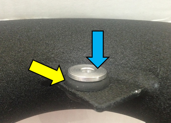
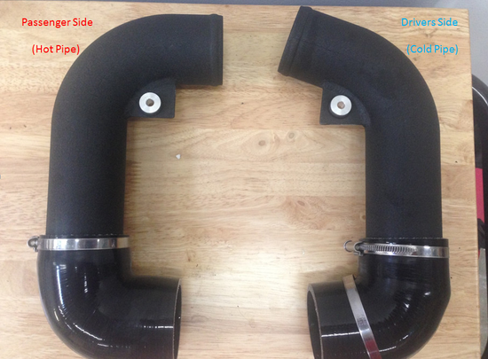
- Install the rubber grommets (yellow arrow) in both the lower hot and cold pipe. Then install the lower pipe mounting spacers (blue arrow) into the grommets so that the flange end of the spacer faces upward. Follow the same procedure for both pipes. Place the end without the logo of the 2.5" silicone 90° on the straight end of the pipe. The longer end (with the logo) should be facing forward as shown in the pictures.
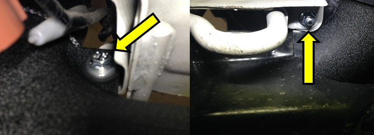
- Using a 10mm socket and ratchet, remove the two screws holding the inner fenders to the core support. This will allow the front of the inner fender that extends up to the front bumper cover to hang down. Then gently press the plastic screw insert out of the core support. You should be left with a small square hole.
- Now install the pipe on the car by sliding the silicone 90° coupler over the passenger side outlet on the intercooler. The bracket with the bushing and grommet should sit on top of the core support bracket.
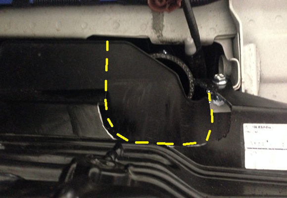
- It's now time to trim the inner fender liner. With the pipe in place, hold the fender liner into position to see where it needs to be trimmed. This can be done with a variety of tools. We had best luck with an air saw, but a rotary tool, sheet metal snips or side cutting pliers can be used. Be sure to wear appropriate eye protection. Here is an example of the passenger side of our car once completed.
TIP: Its much easier to cut less than the desired amount and work your way out than cutting too much the first time.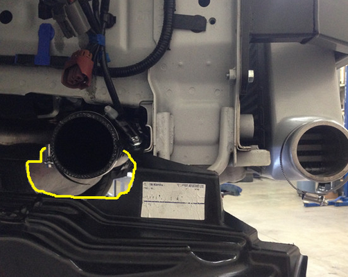
- After the inner fender liner it trimmed, install the plastic under tray. With the fender liner re-attached to the core support., mark the under tray for trimming. Then cut the under tray in a similar fashion as the fender liner. Again, slowly work out toward the desired amount to be cut to prevent over trimming.
- Repeat the last 3 steps with the drivers side.
Installing Hot Side Intercooler Piping
With the core installed and the necessary trimming to the fender liners and under tray done, it's now time to install the piping. For this step you can remove the under tray again.
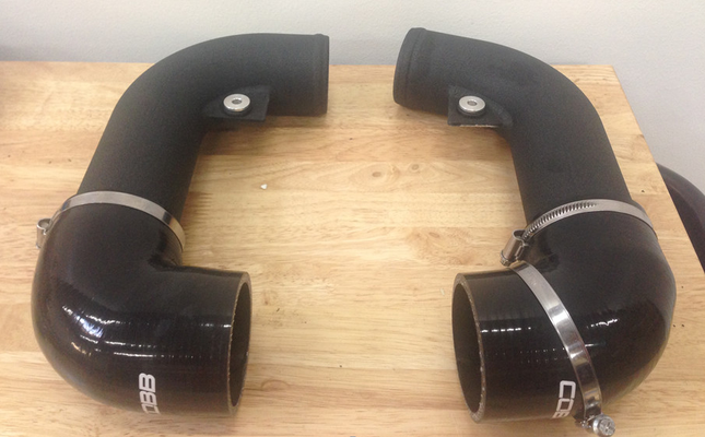
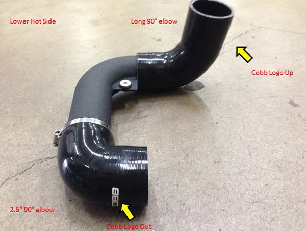
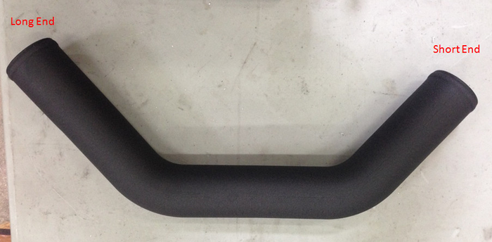
- Starting with the lower hot pipe, now install the Long 90° elbow on the end of the pipe with the bracket and grommet. The longer of the two ends of the coupler with the logo should be facing upward. The pipe with the silicone elbows installed should look like the picture below.
- Slip the 2.5" 90° end of the pipe over the passenger side core outlet. Place the clamps over each end of the silicone before installation. Only loosely tighten as the fitment may need to be adjusted. The bracket with the bushing/grommet assembly should be on top of the square hole core support. Place the bolt through the top of the bushing->fender liner →core support →washer then tighten with an M6 flange nut with a 10MM socket and ratchet.
- Next attach the 2.5" - 2.0" silicone reducer to the turbo. Tighten the clamp slightly but leave it loose enough to move the elbow to align the upper hot pipe.
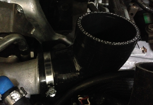
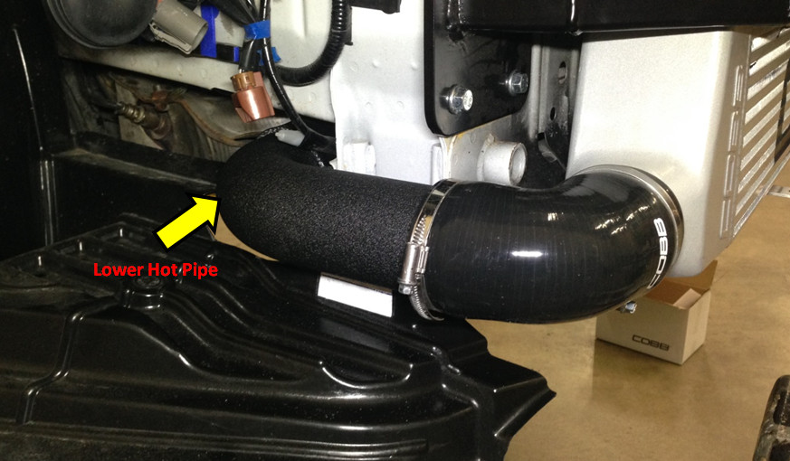
- Now slide a 2.5" coupler over the straight end of the hot pipe. Add a clamp on the 90° end of the hot pipe and install it on the vehicle as shown below.
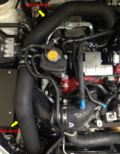
- Next, slide clamps over the straight silicone coupler and the long 90° coupler Install the mid hot pipe. The long end of the mid hot pipe will attach to the lower hot pipe; the short end will attach to the upper hot pipe. Check for clearance between the front of the engine, the chassis, and the radiator fan assembly. Tighten all the clamps with an 8mm wrench or socket once you've determined you like how it is fitting.
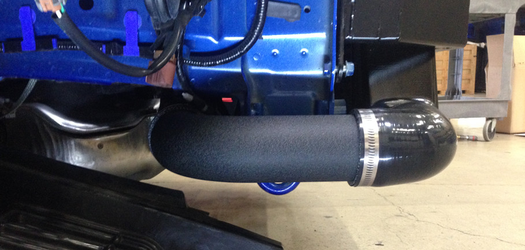
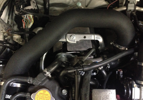
- Once the hot side is fully installed it should look like this:
TIP: Due to limited clearance when tightening the clamp on the lower portion of the mid hot pipe it may be necessary to mark the tube when in place, pull from the vehicle, install the long silicone 90° on the mid hot pipe and reinstall it into the vehicle in that order.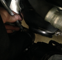
Installing Cold Side Intercooler Piping
The cold side intercooler piping will install in similar fashion as the hot side.
- Starting with the lower cold pipe, slip the Long 90° elbow on the end of the pipe with the bracket and grommet. The longer of the two ends of the coupler with the logo should be facing upward. The pipe with the silicone elbows installed should look like the picture below.

- Slip the 2.5" 90° end of the pipe over the drivers side core outlet. Place the clamps over each end of the silicone before installation. Only loosely tighten as the fitment may need to be adjusted. The bracket with the bushing/grommet assembly should be on top of the square hole core support. Place the bolt through the top of the bushing->fender liner →core support →washer then tighten with an M6 flange nut with a 10MM socket and ratchet.
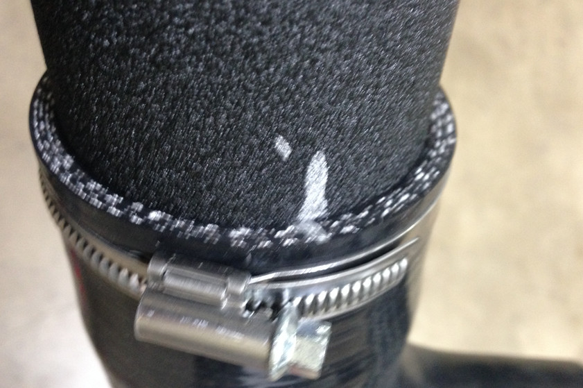
- Next, slip the larger end of the 2.75" -2.5" reducer over the throttle body and tighten the clamp. Then slip a 2.5" coupler over the straight end of the upper cold pipe. Now install the upper cold pipe on the car.
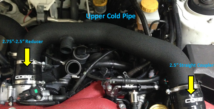
- The WRX cold side routing will look as such:

- The WRX cold side routing will look as such:
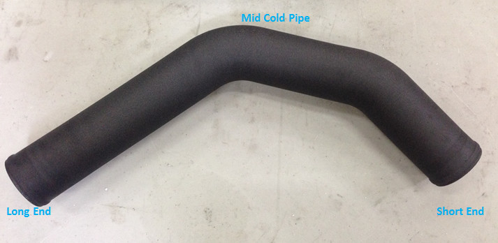
- Next, slide clamps over the straight silicone coupler and the long 90° coupler. Install the mid cold pipe. Check for clearance between the front of the engine, the chassis, and the radiator fan assembly. Tighten all the clamps with an 8mm wrench or socket when you like how it is fitting.
- Once the hot side is fully installed it should look like this:
Installing Bypass Valve
- Slip one end of the BPV silicone coupler over the inlet of the bypass valve. Slip a hose clamp clamp over the coupler and tighten using an 8MM socket or nut driver.
- Next, Slip the BPV nose into the BPV return hose. Tighten the hose clamp using an 8MM socket or nut driver.

- Now slip the silicone BPV coupler onto the BPV outlet on the upper cold pipe.
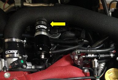
- Reattach the vacuum line to the barbed fitting on the BPV body.
Trimming For Front Mount Core - Bumper Cover
With all the new intercooler components in place, it's time to clearance the bumper cover to fit over the new front mounted core. These instructions are a general guideline as every install will be slightly different. There are a variety of tools one can use to accomplish this task, choose the one that you feel most comfortable with. The following steps are a quick overview of what trimming needs to take place. Go slowly. Be conservative. It's a lot easier to remove a little more than add material back in.
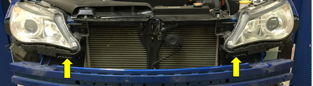
- Start by marking the bumper in the 4 corners of the existing bumper opening. From the edge shown by the yellow arrows, measure inward 1.5" from each corner.
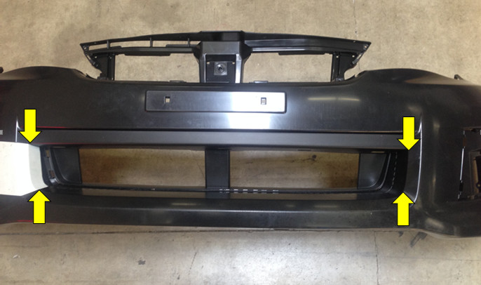
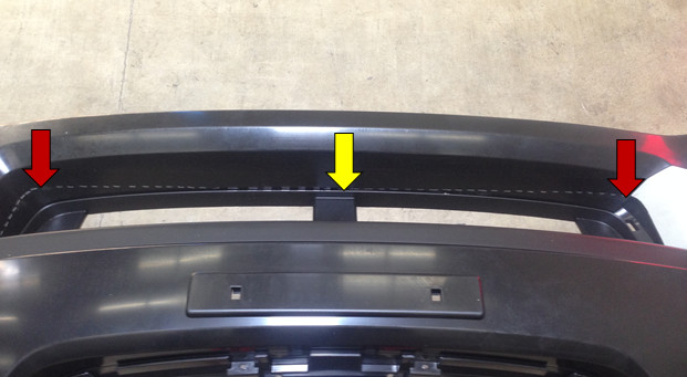
- Looking downward at the bumper from the top side, draw/mark/tape a straight line from the edge of where the painted portion of the bumper meets the black plastic area(yellow arrow) to the points marked in step one (red arrows).
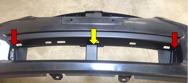
- Now from the bottom of the bumper looking up, draw/mark/tape a straight line from where the center brace in the bumper opening meets the bumper to the points marked in step one as well (red arrows.)
- Now place the supplied template in the opening and align the edges with the line drawn in step 3. Tape in place and trace the ends of the cutout to complete the cut line. (Make sure to transfer the template to something sturdy for us in this step.)

- After double checking all measurements, use the method most comfortable (air saw, utility knife, cutoff wheel, etc.) to you to cut the bumper along the cut line.
TIP: Its much easier to cut less than the desired amount and work your way out than cutting too much the first time. - Once the bumper is cut, loosely install it into place, making sure that you've removed enough material for everything to fit nicely. You may need to remove a small amount more in a few places to get that perfect fit.
- Once you're happy with the bumper clearance, it's time to reinstall everything in the order it was removed. Make sure to go back and tighten the lower bumper supports where the lower intercooler brackets are. Also, double check that all hose clamps are tight and secure.
- Once everything is back installed, make sure you're running a proper ECU calibration for your new piece of hardware and get out there and enjoy the fresh, cooler intake temps provided by your COBB FMIC!
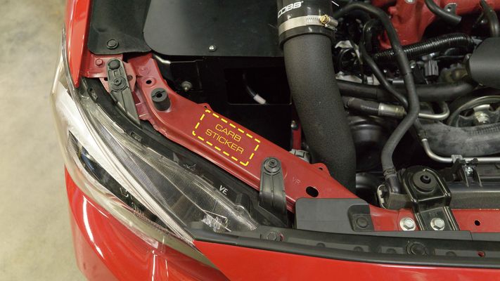
Affix the CARB Sticker
Links
Subaru Installation Instructions
Main Installation Instruction Repository for Subaru Parts
Link to Subaru Map Notes to see what map you should be on given the parts you've added
| Insert excerpt | ||||||
|---|---|---|---|---|---|---|
|