

![]()

Subaru Accesstuner Tuning Guide
Prepared by: Lance Lucas
12/10/2013
Table of Contents maxLevel 2 exclude
Suggested ResourcesAnchor _Toc374521707 _Toc374521707
COBB and Injector Dynamics Injector Characterization Data: http://help.injectordynamics.com/support/solutions/articles/4000009270-cobb-subaru
- These are Excel documents containing exact Injector Characterization data for the factory Subaru ECU for COBB and Injector Dyanmics Dynamics branded fuel injectors. This data should serve as the starting point for calibration after an injector upgrade.
...
Spark and ignition control is straightforward on modern turbocharged Subarus; crank and camshaft position are measured via reluctor and Hall-effect sensors, depending on model/year, and are then synchronized within the ECU, which operates four coil-on-pack ignitorless coils in a sequential firing order. Ignition system upgrades are rarely needed as the factory hardware has been proven shown itself to not only be durable but also capable of supporting roughly triple the factory power levels with no meaningful degradation to spark energy or combustion quality.
All turbocharged Subarus for USDM markets to-date (MY2002-MY2014) feature port injection, controlled a traditional 3 bar bypass fuel pressure regulator with manifold reference rate of 1:1. The factory fuel rails are in a series configuration. A traditional in-tank hanger, located in the passenger side of the saddle-style fuel tank, handles fuel delivery from the tank. Like other Japanese vehicles, this assembly also contains a "siphon" system operated by the returning fuel flow to sump the driver's side fuel tank reserves. Fuel starvation during right-hand turns is a known limitation of the design; many track vehicles and fast street cars use an auxiliary surge tank to alleviate this issue.
...
Factory specified injectors vary, mostly along vehicle generation lines, though all are provided by Denso. The 2002-2005 WRX utilized ~440cc topfeed top-feed injectors (light blue). The 2004-2006 STI, 2005-2006 LGT, and 2004-2005 FXT featured ~550cc sidefeed side-feed injectors (yellow). The 2007-2014 STI, 2006-2014 WRX, 2006-2013 FXT and 2007-2012 LGT use ~565cc topfeed top-feed injectors (dark blue), though the part numbers and body coloring may have changed across a few years. Uprated sidefeed side-feed injectors have proven to be particularly problematic; even the factory sidefeed side-feed injectors are known to have a high failure rate. Topfeed Top feed conversions are common practice, even for otherwise-stock vehicles.
Mass Air Flow is measured by a traditional Denso-provided integrated intake air temperature and hot-wire mass air flow airflow meter. This is located in an "airbox" MAF housing from the factory or traditional "filter-on-a-stick" intake housing in the aftermarket. No post-compressor or post-IC temperature pickups are used unless the vehicle has been converted to use our custom Speed Density code, . Speed Density is when an alternate IAT sensor is installed into the post-IC charge piping or intake manifold. Accurate Mass Air Flow AirFlow measurement, meaning correct MAF recalibration following intake hardware changes, is exceptionally critical to accurate fuel calculations and delivery.
Our custom Speed Density code allows for the computation of mass air flow airflow and load (which are functions of one another in the Subaru ECU) based on the traditional PV = nRT and volumetric efficiency models. When using the Speed Density method for tuning, Mass Air Flow AirFlow (and thus load) is calculated using a Volumetric Efficiency model that includes adjustable engine displacement, air temperature compensations, coolant temperature compensations and others. Assuming proper end-user input of critical items of said variables, the model is highly effective for very precise mass air flow airflow estimation. This style of tuning is traditionally used by those whose power demands exceed that which a MAF housing of ~80mm or smaller internal diameter can provide , or those who require greatly customized turbocharger and intake tract configurations that do not allow for proper draw-through MAF or recirculating BPV positioning.
...
Ignition advance, and total applied timing, is calculated and controlled by a somewhat complex strategy within the factory ECUs logic. With some basic knowledge and a clear understanding of the various tables and monitors involved, however, the system is not only very accurate, but it is also exceptionally easy to tune. Here are the basic formulas for how total ignition advance is calculated:
...
Because the DA value applied is multiplied against the DAM value, the general shape of the primary DA tables is by and large determined by the relative probability of inducing detonation under given conditions. When the engine load is low, or RPM is high, the engine is more resistant to detonation. When the engine load is high or RPM is low, knock is more likely. With this, the factory generally uses the most DA where torque is highest, in order to achieve the largest dependence and response to DAM changes. In general, the Dynamic Advance tables are "pre-tuned" based on the calibrator's preference, then the Primary Ignition table is shaped around it as such to generate the total final Ignition Timing value. Spreadsheet programs such as Excel can be very useful for overlaying the Primary Ignition and Dynamic Advance tables to help visualize the total timing value requested as well as look for any anomalous or insane values.
See "STi-Specific Considerations" below for additional information specific to the STi models.
- Dynamic Advance Multiplier (DAM): This value represents a global adjustment to the Dynamic Advance component ignition timing. In general, this value is determined by historical detonation/knock as well as the default mapping value. For the 2.5L ECU, DAM is stated as a decimal ranging from 0 to 1. For the 2.0L ECU, DAM is stated as an integer between 0 and 16. DAM will tend to vary the most immediately following a reflash or ECU Reset procedure. The starting value for DAM is an adjustable value within the Ignition Tables -> Advance (Dynamic) submenu. Various thresholds, including RPM and load, and determine when DAM can or should be evaluated for potential increases or decreases.
...
- Knock Sum (where applicable): This is a somewhat arbitrary monitor and logging value that should only be analyzed under the specific conditions you wish to evaluate, such as during wide-open throttle (WOT) operation over a set RPM range. Some later ECUs can report Knock Sum on a per-cylinder level, some only on a global basis. It is useful to determine if a particular cylinder is especially prone to detonation in relation to the others; however, it must be noted that Cylinders #1-3 lack knock detection accuracy due to their relative distance from the knock sensor. Cylinder #4 can be heard most reliably thanks to being located directly below the knock sensor, which has a difficult time perceiving real engine noise over the noisy boxer engine on the more distant cylinders. If a noise is perceived, this value will increment at all times, regardless of if the knock detection system is deemed to be accurate or not. It is not uncommon to see these values increment under even the most mundane conditions, such as idling or while operating the vehicle at slow speeds in a parking lot. It must be emphasized that this is simply an indicator that a noise of unknown source has been detected, which must still be evaluated by the ECU for source, sanity and plausibility (IE, is it likely that the engine is actually detonating and on which cylinders).
- Compensations: Within the framework above, this is a summation of various ignition timing compensations. Depending on the year and model, these exist on as per-cylinder corrections, per-gear adjustments, intake air temperature based adjustments, etc. Depending on how the compensation tables are calibrated and the conditions under which the vehicle is operated, these compensations can wildly alter total timing or conversely have a very small effect. We tend to use minute or zero compensation for "normal" operating conditions – such as mild temperatures at sea level elevation on a fully warm but not overheating engine – and then add compensations for when those types of conditions are at more extreme values, such as relatively cool or hot air temperatures, high elevations or when the engine is overheating.
...
Assuming DAM stabilizes at its maximum value following the reflash/reset, pay very close attention to FKC and FKL during the calibration process. Depending on the model and year, the minimum timing increment varies between roughly -1 and -2 degrees. The decrement values can be viewed, or adjusted in unique circumstances, under the Knock Control submenus. Single increments of corrections to FKC and FKL will be observed from time to time during the calibration process; please note that FKL is truly a "learned" value and will be applied under those Load/RPM conditions until it is reevaluated and potentially removed. Intermittent single increments, such as -1.40 for a 2008-2014 STI, are not uncommon, but if proven repeatable under WOT conditions, an adjustment to the Primary Ignition table should be considered. Any value larger than the single increment is nearly certainly an indication of prominent noise and calibration adjustments should be made.
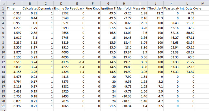
Ex: Data log Datalog demonstrating a single negative Feedback Knock Correction increment while performing a dyno calibration on a Stage2 2012 STi. This knock event was repeatable and only observed after raising ignition timing from a previous knock-free level while. Restoring the lower values eliminated the detonation. Note that the safety and power of the dyno tuning process allowed this operator to quickly abort a run once they observed anomalous operation.
...
In general, the Subaru engine does not suffer from any extreme efficiency irregularities under full power, so a smooth timing curve free of unreasonable jumps or dips is usually desirable. Pay attention to the Ignition Timing monitor for large abrupt changes to ignition timing and smooth the Primary Ignition table accordingly. Closely monitor torque changes.
Pay careful attention to the various ignition timing compensation tables, in particular, the Ignition Timing Compensation (Intake Temperature) table. This can play an extremely large role on in the timing values observed on the dyno, especially when dyno-room airflow causes an ambient vs. IAT temperature discrepancy. Conversely, it is important that the values in this table be appropriately set up to help reduce the potential for detonation as air temperatures rise. Other compensations, such as those for Per-Gear and Per-Cylinder adjustments, can be used advantageously to account for the increased mechanical load to the vehicle or airflow imbalances within the engine. However, you MUST account for how the compensation will adjust timing as those variables reach more extreme states, such as a very hot afternoon or while accelerating at WOT in 6th gear.
...
Now that we have outlined the various tables, monitors and logic that encompass the ignition timing and knock control strategies, we must actually adjust the timing curve and various thresholds in order to maximize efficiency and power (at the minimum cylinder pressure levels necessary for each) while minimizing the likelihood for inducing detonation. In practice, the objective of ignition timing calibration is to find MBT (or MTBT), which is Minimum timing for Best Torque. Finding MBT can only be safely accomplished with a good loading chassis dyno that has the ability to load the vehicle and measure the torque output at the same time. Chassis dynos such as Mustang Dynamometer, Mainline DynoLog, DynoCom, Bosch, and Dyno Dynamics have this ability, as do some traditionally inertia-based dynos such as Dynojets that are now being upgraded to include Eddy Current retarders. You can start in the higher gears (lower engine RPM) and have the chassis dyno to hold the vehicle and give you the torque output of the vehicle at a an RPM breakpoint on your ECU calibration. You can start out at very light (low TPS) loads holding the vehicle in one specific cell in the Primary Ignition table and slowly add ignition advance until the vehicle does not make any more torque or gets close to the knock threshold for the motor. One suggestion is that you increase ignition advance for each particular cell until you see that torque no longer increases with the additional ignition advance. Now back off 2-4 degrees of ignition advance to keep the calibration on the safe side. Once you find where the motor produces the maximum amount of torque with the least amount of ignition advance, this is MBT. Tuning for cruising and partial throttle MBT will take a very, very long time and is not suggested unless you are very experienced with the particular chassis dyno you are using and the engine you are tuning. OEM calibration teams have vast resources at their disposal for calibrating the engine under these conditions, so their work is to be trusted in lieu of more accurate data. It is critical, however, to ensure that the ignition timing curve is very well calibrated over the entire "boosted" range of the engine, which can be accomplished by beginning WOT tuning at the minimum mechanical boost pressure, methodically adjusting each load range for MBT as boost pressures are increased. Please take into account that once you exceed MBT (Minimum spark advance for Best Torque output); it is possible to make less power with more ignition advance. Due to the various properties of the Subaru engine, it is common to encounter the detonation threshold before MBT when advancing ignition timing under boosted conditions. It is important to re-scale the load axis as necessary on the Primary Ignition and Dynamic Advance tables to ensure that you have suitable resolution for ignition timing adjustment when power levels greatly exceed that of the factory vehicle and load axis scaling.
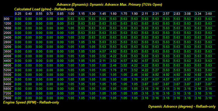
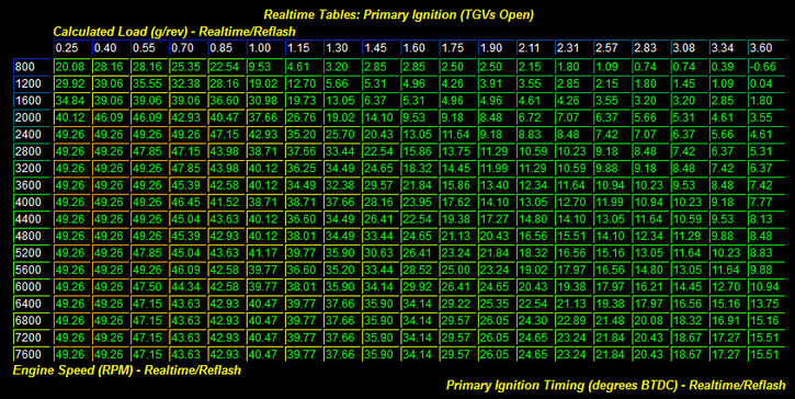
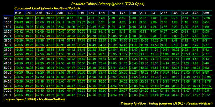
Ex: Here are the Primary Dynamic Advance TGVs Open and Primary Ignition TGVs Open table from a typical Stage2 2013 STi running on 93 octane gasoline. Note that the load axis has been rescaled to a maximum value of 3.60; peak load values of ~3.35 were observed during dyno tuning (stock load scaling ends at 2.95 g/rev). This extra resolution allows for an appropriate change to ignition timing should post-tune load values exceed those observed during the tuning session.
Assuming a safe timing map and accurate fueling have been established, one common strategy for quickly developing a timing curve very close to either MBT or the knock threshold is to remove a set amount of timing – such as 2 degrees – over the entire Load/RPM range, perform a WOT test run, then repeat the run with the timing added back. Fortunately, the Accesstuner software allows for tuning Primary Ignition timing in "Real-time" without requiring a lengthy reflash process between changes. This facilitates the results from timing adjustments to be observed immediately under repeatable dyno conditions. This capability facilitates far more accurate and rapid ignition timing calibration processes.
Anywhere that torque has noticeably increased demonstrates that the increase to timing was desirable in that range; anywhere that power is unaffected is likely already at or above MBT and a reduction in timing should be considered. If both a power increase and new knock corrections are observed with the advance in timing, the entire tune must be considered for causes (excessive boost, lean air/fuel mixture, etc.). Raising boost then adjusting the new higher load columns/values in the same fashion will eventually shape a full timing table with accurate ignition timing at all boost levels.
Generally speaking, a turbo-charged turbocharged Subaru motor will run the least amount of ignition advance near peak torque and ignition advance will generally rise as RPM rise in order to keep up with the increasing piston speed. This trend is normal for most internal combustion spark ignition motors; as VE (Volumetric Efficiency) increases the amount of ignition advance a motor needs will decrease. As VE increases at WOT, when the turbo is producing boost, ignition advance will go down to its lowest point by peak torque then it will slowly increase during the torque plateau. This is not due to decreasing VE but rather to keep up with the increasing piston speeds. Once torque begins to fall off at higher engine speeds, ignition advance will generally increase at higher rates. This is due to the decreasing VE and is also done in order to keep up with the increasing piston speeds; you have to start the burn earlier so that the pressure wave expansion occurs at the optimal time.
There are some known situations where it is very common to see timing corrections in response to a perceived noise. In general, these events are not of concern and should not be particularly alarming unless the corrections are very large. The corrections made during these scenarios are often due to shifting or rapid movements within the drive train and not necessarily to harmful noises generated within the engine:
- On from-stop takeoffs, while clutching out
- During gear shifts (this can be exacerbated by "power shifting" or using FFS)
- While attempting acceleration at a low RPM in a high gear
- Under cruising-type conditions at freeway speeds
- After sharply pressing/depressing the accelerator pedal
Due to the various grades of fuel available throughout the US and abroad, ignition timing values can vary greatly depending on the relative geographic and environmental conditions under which the vehicle is being operated. By definition, octane rating is determined by the fuel's ability to resist uncontrolled ignition; it is quite literally referred to as the "anti-knock index" (AKI) and is an average of two different methods for determining the theoretical resistance to detonation/knock relative to a reference fuel or engine operation operating conditions. The methods are "RON" and "MON"; AKI is calculated as "(RON+MON)/2", which is the common marking on fuel dispensing pumps. "Higher octane ratings correlate to higher activation energies: This being the amount of applied energy required to initiate combustion. Since higher octane fuels have higher activation energy requirements, it is less likely that a given compression will cause uncontrolled ignition, otherwise known as auto ignition autoignition or detonation." "Octane Rating." Wikipedia. 29 Jun 2011. <http://en.wikipedia.org/wiki/Octane_rating#Effects_of_octane_rating>. Thus, the octane rating of the fuel being used will have a direct impact on the engine's ability to resist detonation and knock. You should always use the "premium" pump fuel available in your area; we also suggest the exclusive use of fuels from Top Tier Retailers For more information, please visit: http://www.toptiergas.com, when possible. You will generally find that higher octane fuels have longer burn times or combustion duration and will require more spark advance in order to reach its MBT value. This is an important phenomenon to note when using leaded race gas or other very-high octane fuels as power loss can be observed if the timing is not properly advanced. Energy The energy released from combustion that is not used during the power stroke is wasted during the exhaust stroke, which causes EGT and EGBP to rise.
...
As can be seen, the "big three" of boost, ignition timing, and air-/fuel can all play an integral part in causing or contributing to detonation/knock. While dyno tuning, it is advised that you begin with lower-than-optimal ignition timing value, then slowly work upwards while closely monitoring dyno output for torque changes and dyno logs for timing corrections in response to detonation events.
If attempting to calibrate ignition timing under road conditions, extra care must be taken to ensure that timing is not advanced beyond MBT; simply tuning to the knock threshold can lead to a calibration with excessive and unnecessary ignition advance under conditions when the knock threshold is above the MBT threshold. This most commonly occurs with high octane fuels such as leaded race gas and E85. There are some basic spreadsheets and log analysis tools available that can help estimate torque output from road logs that include time and vehicle speed. Other quantifiable metrics such as trap speed or acceleration rate can be used in lieu of accurate torque data, though a precise measure of power against RPM is always preferred.
For an engine with stock internal components and valve train, the factory knock detection system is very accurate. As internal components and valve train the valvetrain are upgraded, the factory knock system's accuracy can be degraded by the increased background mechanical noise levels. Under these circumstances, it can be extremely beneficial to utilize advanced knock monitoring hardware, such as auxiliary knock amplification and monitor headset – commonly referred to as Detonation Cans, or "det. cans," to ensure the knock control system is able to appropriately discern knock from mechanical noise. When running pump gas, tank-to-tank variability can play a large role in determining the detonation threshold, so it is very important that the knock control system be effective at mitigating detonation when it occurs.
...
As outlined in the introduction, mass air flow airflow is used to determine the mass of fuel needed for every fuel injection event. This is done by calculating the targeted or desired air/fuel ratio (AFR), which is quite literally a ratio for a given mass of air against a required mass of fuel. The ECU determines the final fueling target as a Fuel/Air Equivalence Ratio (more below), then performs calculations using the various injector characterization tables, such as Latency and Scale, to determine a final driven or "on time" for the fuel injectors.
Under Closed Loop operation, the fuel target is primarily dictated by the Closed Loop Compensation (Load) tables, which are used as an adder against a normal stoichiometric value for gasoline of 14.7 AFR (more precisely, 1.0 lambda). In this case, the tables traditionally contain negative values to achieve the net result of targeted AFR values slightly richer than 14.7. OEM Subaru calibrators likely used values slightly richer than 14.7 to improve combustion quality (reduce misfiring) and control exhaust gas temperatures. Closed Loop fueling errors are corrected for via the A/F Correction #1 and A/F Learning #1 functions based on front O2 sensor feedback; some models use A/F Correction #3 and A/F Learning #3 feedback functions based on the rear/secondary O2 sensor feedback. This phenomenon can be minimized or eliminated using tables under the Closed Loop submenu in order to reduce variability in final fueling.
...
It is important to note that while the Primary Open Loop Fuel table should be a reasonably close representation of final observed tailpipe AFR , and some variance is inevitable. The equations for determining injector on-time based on a theoretical desired AFR value depend on many assumptions and variables. One of the leading factors for this is overall fuel chemistry. The OEM calibration and fuel injector data assumes "E0" gasoline; many areas now exclusively sell fuel with 10% ethanol (E10), which alters the amount of injection time required to achieve the same fuel/air ratios as a fuel that does not contain ethanol by roughly 3-5%. E85 and other alternative fuels are discussed in-depth later in this article.
...
- Fuel Injector Latency: This is the injector latency (offset) based on battery voltage. This is also sometimes referred to as injector opening time or dwell.
- Fuel Injector Pulse Width Limit (Min): This is the minimum limit for injector pulse width when fueling is enabled. This limit is active except during higher RPM/load/throttle initial lift-throttle (tip-out) conditions.
- Fuel Injector Scale: This value is the injector pulse width (in microseconds) for stoichiometric fueling per gram of calculated load. This value is the basis for the base pulse width (fuel injector scale * calculated load), which is used as a base for all fueling calculations. Because this value is a direct multiplier in the final pulse width calculation, smaller numbers are used for larger injectors.
- Fuel Injector Trim (Small IPW) [ALL 2.5L MODELS]: This is the fuel injector pulse width compensation (%) based on the last calculated non-compensated injector pulse width. This compensation is applied when the corresponding maximum injector pulse width and RPM thresholds are not exceeded.
- Fuel Injector Trim (Small IPW)(Max. IPW) [ALL 2.5L MODELS]: This is the maximum injector pulse width (last calculated non-compensated) in which the "Fuel Injector Trim (Small IPW)" table will be applied. Corresponding RPM threshold must also not be exceeded.
- Fuel Injector Trim (Small IPW)(Max. RPM) [ALL 2.5L MODELS]: This is the maximum RPM in which the "Fuel Injector Trim (Small IPW)" table will be applied. Corresponding IPW threshold must also not be exceeded.
- Fuel Injector Latency Adder (Small IPW) [2.0L SD ONLY]: This is a compensation (raw mms) to the current injector latency based on the current injector pulse width. This can be useful to tune for the non-linearity of larger injectors at low injector pulse widths to improve idle/low load behavior. NOTE: No stock data is provided for this table as it has been custom-coded by COBB Tuning in the absence of proper factory compensation logic for non-linear pulse compensation.
- Fuel Injector Trim (Per Cylinder)(#1-#4)(Fuel Multiplier Offset) [04-05 FXT MT/AT, 05-06 LGT MT/AT, 04-06 STI]: This is the per injector fuel adder for the cylinder given based on the last calculated non-compensated injector pulse width.
- Fuel Injector Trim (Per Cylinder)(#1-#4)(IPW Compensation) [06-08 FXT MT/AT, 09-12 FXT, 07-09 LGT MT/AT, 10-12 LGT, 07-09 LGT spec, 07-12 STI, 06-08 WRX MT/AT, 09-10 2.5GT, 09-12 WRX]: This is the per injector fuel pulse width compensation for the cylinder given based on the last calculated non-compensated injector pulse width.
- Primary Open Loop Fueling: This is the desired primary fueling in open loop when the Dynamic Advance Multiplier (DAM) is greater than or equal to the threshold determined by the "Primary Open Loop Fueling (High Detonation) DAM Threshold" table and the minimum threshold, as determined by the "Primary Open Loop Fueling Min. Activation" table, is met. The minimum limits and compensation values, as determined by the "Primary Open Loop Fueling Min. Enrichment..." and "Primary Open Loop Fueling Compensation..." tables, are also applied to determine the final primary fueling.
- Closed Loop Compensation (Load): This is the compensation to the closed loop fueling target based on calculated load and RPM. This table's value is added to the target, along with other compensations, to determine the final target. Note: Positive compensations (i.e. leaner impact) in this table will potentially force open loop fueling during closed loop. As mentioned, this table usually contains negative values, which causes for a commanded fueling target richer than stoichiometric.
- Tip-In Enrichment: This table's values represent additional injector pulse width during throttle tip-in. This enrichment is dependent on the tip-in enrichment activation and duration tables. The tip-in enrichment compensation tables can also influence the final enrichment. This function is sometimes referred to as an "accelerator pump" as it serves a similar function to a component of a carburetor of the same name. Tip-In Enrichment is used to accommodate for a temporary lean condition that results from a rapid throttle plate movement. Among other causes, this lean condition exists from a temporary time delay in mass air flow airflow measurement as well as a "drying" of the post-injector intake tract and cylinder head ports when the throttle plate is opened quickly.
...
- Load (grams/rev) = Final Mass Air Flow Airflow (grams/second) ÷ Engine Speed (revs/min) × 60 (sacs/min)
- Example: 300 / 6000 * 60 = 3.0 (grams/rev)
- Example: 300 / 6000 * 60 = 3.0 (grams/rev)
- A/F Correction #1 = short-term fuel trim multiplier
- Example: 1.0 = no change, 0.95 = -5% change, 1.05 = 5% change
- Example: 1.0 = no change, 0.95 = -5% change, 1.05 = 5% change
- A/F Learning #1 = long-term fuel trim offset to the short-term multiplier
- Example: 0 = no change, -0.05 = -5% change, 0.05 = 5% change
- Example: 0 = no change, -0.05 = -5% change, 0.05 = 5% change
- Final Fuel Multiplier = Final Fuel-Air EQ Ratio
- Example: 1.10 = 10% richer than stoic. 0.90 = 10% leaner than stoich.
- Example: 1.10 = 10% richer than stoic. 0.90 = 10% leaner than stoich.
- Base IPW Calculation (microseconds) = Final Fuel Multiplier × Fuel Injector Scale × Load × (A/F Corr. #1 + A/F Learn #1)
- Example: 1.20 * 3150 * 3.0 *( .98 + .02) = 11340 (microseconds)
- Example: 1.20 * 3150 * 3.0 *( .98 + .02) = 11340 (microseconds)
- Final IPW (microseconds) = Final Fuel Multiplier × Fuel Injector Scale × Load × (A/F Corr. #1 + A/F Learn #1) × Per Cylinder IPW Comp. × Small IPW Comp.
- Note: Earlier ECUs do not have per-cylinder IPW compensation, but rather per-cylinder fuel multiplier compensation.
- Note: Earlier ECUs do not have per-cylinder IPW compensation, but rather per-cylinder fuel multiplier compensation.
- Estimated Conversion for Injector Scalar to E0 Gasoline Flow Rate = 2707090 ÷ Fuel Injector Scale
- Example: 2707090 / 4813 = 562.45 ~(cc/min)
...
One of the most critical aspects of engine calibration is the data that characterizes the various properties of the fuel injectors, such as flow rate and offset. If these values are not precisely adjusted, other aspects of the calibration may be skewed to account for the variance, such as the MAF or Open Loop Fueling tables. This can lead to wildly variably fuel injector control (and thus, air/fuel ratios) as environmental and operational conditions change over time. High-quality aftermarket fuel injectors will come with this data; we currently host a spreadsheet online that summarizes the data we currently have available in an Accesstuner-friendly format. Aftermarket injector providers should be closely scrutinized based on their ability to provide you with complete characterization data with which to begin the conversion and calibration process. The values within the spreadsheet will be a very accurate starting place, erring to the slightly rich side (Injector Fuel Scale too high) to begin initial tuning. 
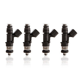
Ex: COBB Tuning 1000cc injectors are provided in collaboration with Injector Dynamics, a close technical partner. These injectors utilize Bosch-provided cores and are sold in closely matched sets during that meet strict specifications following rigorous testing procedures. Outliers are discarded. Exact injector flow scaling, latency, and small IPW trim data is available upon request.
...
In lieu of data from the manufacturer or as endorsed by COBB Tuning, input the calculated value as a starting Fuel Injector Scale value. When calibrating injectors without a known injector scale value, we suggest you install the stock intake system (with stock MAF calibration) and run with stock level fuel pressure levels. DO NOT attempt to tune for an aftermarket Intake and aftermarket injectors at the same time. Observe A/F Correction #1 and A/F Learning #1 within the Dashboard. While operating the engine in Closed Loop mode (see monitor) at full temperature (coolant temperature between 180-195 F and intake air temperature +/- 15 degrees F of ambient temperature), you can make adjustments to the Fuel Injector Scale value until the A/F Correction #1 + A/F Learning #1 are as close to zero as possible, +/- 5% is generally acceptable. The closer you can get to 0% is ideal. Operate the engine through as much of the idle and cruising range as is feasible. If fueling is observed to be universally lean (positive trims), scalar should be increased to add fuel , and vise-versa.
Fuel Injector Latency can be adjusted by observing fuel trims at idle and very low pulse widths with the factory intake and MAF calibration in place. Again, factory intake hardware and factory fuel pressure values are critical to reducing variables and achieving accurate results. Changes to latency values will have the most impact where IPW is lowest. If fueling is observed to be universally lean (positive trims) at low pulse width values, latency should be increased to add fuel, and vise-versa. A common error is adjusting the MAF curve's lower range to account for fueling errors near idle, which are actually frequently caused by incorrect latency values.
...
An aftermarket intake will affect your A/F Correction #1 and A/F Learning #1 values at idle and part throttle, making it nearly impossible to find accurate Injector Scale or Latency values. If you have an aftermarket intake, please use the above equation to establish your initial Fuel Injector Scale and Latency values then move forwards with the MAF recalibration as necessary.
| Anchor | ||||
|---|---|---|---|---|
|
| Anchor | ||||
|---|---|---|---|---|
|
...
It is no coincidence that a significant number of factory EFI implementations rely on a mass air flow airflow meter for airflow calculation. While contingent on certain factors, such as a sealed intake system free of leaks, using a mass air flow airflow sensor allows for precise airflow measurement – and thus application of fuel – under virtually all conditions, both environmental and mechanical. It inherently accounts for many otherwise-critical factors, such as engine wear (leakdown) and ambient air temperature.
In general, it should only be necessary to adjust the MAF sensor calibration if the intake housing has been changed from stock. If the intake housing has not been changed, altering the MAF curve is usually an incorrect adjustment for an unrelated calibration error or mechanical issue with the vehicle. It is highly recommended to keep a new MAF sensor on hand for testing purposes, as their measurement accuracy will degrade over time. If this sensor's accuracy is measurably degraded, the calibrator may be inclined to incorrectly adjust the MAF curve, incorrectly assuming a simple vehicle-to-vehicle variance is the a cause.
Overall The overall performance of an aftermarket MAF housing will depend largely on its design, construction materials, location, and air filter choice/location. In general, laminar flow (http://en.wikipedia.org/wiki/Laminar_flow) is desired across the MAF sensor, which will lead to a consistent and predictable airflow curve across the sensor's usable range. Some intakes, such as models offered by COBB Tuning and AEM, offer "air straightening" fins in order to smooth the airflow before it approaches the mass air sensor. Sharp bends, changes to diameters, boundary layer (http://en.wikipedia.org/wiki/Boundary_layer) properties and numerous other factors can degrade the consistency of quality of the airflow across the sensor, hence the careful engineering and design of the factory airbox system. Intake housings made of thin metal materials, such as aluminum or stainless steel, can be prone to dimensional instability as the temperature of the housing itself changes and the internal diameter of the housing grows and shrinks. Pragmatically, many aftermarket intakes suffer from variable performance based on whether or not the radiator fans are running and blowing air across the air filter assembly. Careful consideration must be given to all aspects of aftermarket intake design and implementation. 
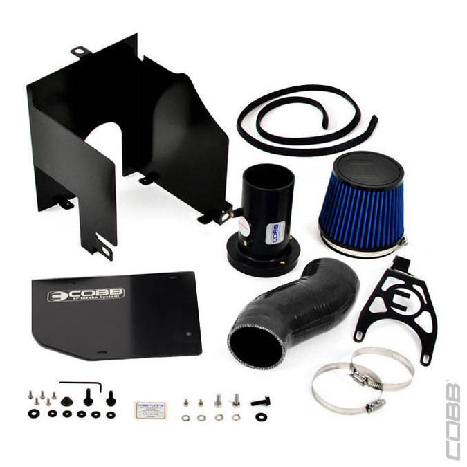
Ex: COBB Tuning SF Intake and Airbox Combination system. The MAF housing is made of a composite material for dimensional stability with temperature changes and incorporates air straighteners to promote laminar flow. The complimentary airbox shields the intake from hot engine-bay air and wind from the radiator fans during their operation. A mounting bracket holds the housing and filter firmly in place and free of vibration.
...
Speed Density allows for Mass Air Flow to be calculated, rather than measured, using manifold pressure, manifold air temperature and volumetric efficiency (or pumping efficiency) as the primary inputs. Our implementation also allows for compensation based upon engine coolant temperature and barometric pressure. Coolant temperature can impact how well the fuel is atomized; barometric pressure can change relative exhaust back-pressure levels.
Extended calibration on a load-bearing dyno is a virtual requirement for completing a full Speed Density tune. Using a load-bearing dyno, the dyno operator can lock engine speed to precise values to allow for Volumetric Efficiency table adjustments under steady-state operations. Increasing the throttle position while rotating speed is locked will increase manifold pressure and allow for calibration across the entire range of possible manifold pressures at a given rotational speed (RPM).
Please read our complete Speed Density tuning guides for a detailed overview of software usage, hardware requirements, and calibration concerns.
...
From the factory, all Subaru ECUs use four distinct learning ranges for learned long-term fuel trims (LTFT). These are known as "A/F Learning A/B/C/D" and can be logged or viewed in realtime while Live Connected to the ECU. The learned value being actively applied at any given time can be monitored by viewing the "A/F Learning #1" monitor. The three break-points given in the "A/F Learning #1" table will determine the thresholds between each range (A-B, B-C, C-D). The min for range A and max for range D are is determined by "A/F Learning Modify Airflow Limit (Min)/(Max)" tables, respectively. Keep in mind that this is only the cap for when learning is active, the actual learned value will be applied at all times while above the C-D threshold value. This behavior can be problematic for aftermarket or performance tuning as minute MAF scaling errors under cruising conditions can have a broad impact over the entire open loop range of operation.
...
To calibrate the MAF curve during Closed Loop fueling, adjust MAF g/s against MAF voltage up or down based on total observed fuel trims errors. If the summation of A/F Correction #1 and A/F Learning #1 is +6%, highlight the MAF Calibration cell for that particular MAF voltage and hit the "M" key. The correct multiplication value for this particular situation would be 1.06; this adjustment will now tell your ECU for that particular MAF voltage you now have a 6% greater MASS of air entering the motor so 6% more mass of fuel should be injected. After this adjustment is made then your summed A/F Correction #1 and Learning #1 should be much closer to zero.
To calibrate the MAF curve during Open Loop fueling, adjust MAF g/s against MAF voltage up or down based on wideband air-/fuel ratio measurement against the ECU's targeted AFR value, which can be observed by monitoring Commanded Fuel Final. If actual wideband AFR is observed to be 12.0 when Commanded Fuel Final is observed to be 11.0, increase MAF g/s over the range for which the error exists by ~+9% or multiply by 1.09 (12.0/11.0) After this adjustment is made, observed wideband readings should very closely match Commanded Fuel Final.
It is important to remember how Load is calculated – MAF / RPM * 60, so any changes to the MAF curve will cause a resulting change to the Load values observed for the same operating conditions, so it is important to finalize the Mass Air Flow calibration before wholesale changes are made to any tuning table that uses Load as an axis value.
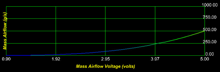
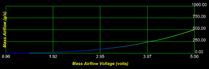
Ex: Example Mass Air Flow sensor curve from the COBB Tuning SF Intake system for the 08+ WRX/STi. Note the smooth and predictable shape, indicating both quality hardware and accurate calibration. Peaks, valleys and other unnatural changes to the shape of the MAF curve can indicate a hardware issue or calibration error.
...
Calibrating the Volumetric Efficiency table during Closed Loop fueling is very similar to the aforementioned methodology for MAF-based tuning, however, you will now be editing a much larger table. Row by row, column by column, the VE table must be adjusted to account for fueling errors in the same fashion as the normal MAF curve, using the factory fuel trims to adjust while in Closed Loop operation. For the open loop, we again compare observed wideband data against Commanded Fuel Final.
Unlike a MAF calibration, it is not entirely uncommon to have incongruent peaks or valleys within the Volumetric Efficiency table, as this table represents the engine assembly's "final" operating efficiency for any given manifold pressure and RPM value, including all hardware from the intake air filter to muffler tip. VE values between 50%-70% at idle and 90%-120% under full boost WOT operation are is common, depending on camshafts, cylinder heads, turbocharger kit, intake and exhaust manifolds, etc. An increase in the Volumetric Efficiency value will cause an increase in fueling, as the mass of air entering the engine will be calculated to be higher, and vise-versa.
As with traditional MAF tuning, changes to the VE Table will cause a resulting change to the Load values observed for the same operating conditions, so it is important to finalize the Volumetric Efficiency calibration before wholesale changes are made to any tuning table that uses Load as an axis value.
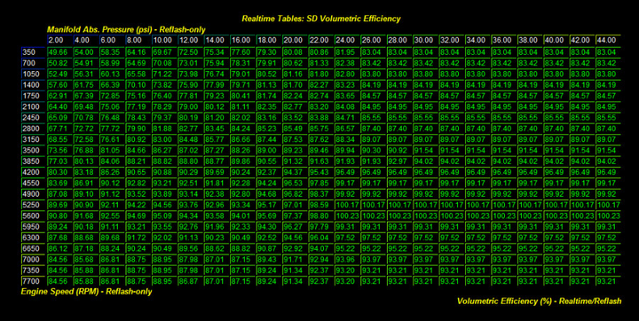
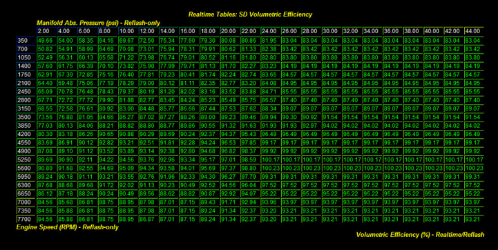
Ex: Example Volumetric Efficiency table from a 2005 STi utilizing a Blouch Dom3.0 turbocharger, built shortblock short block with stock heads and camshafts and front-mount intercooler. Note the smooth shape and predictable increases in VE as manifold inlet pressures rise. Engines with an upgraded cylinder head and camshaft packages will display increased VE at higher RPM.
...
- Primary Open Loop Fueling Min. Enrichment (TPS) [02-05 WRX]: This is the minimum enrichment limit for primary open loop fueling (if active) based on the throttle position. This minimum is also applied before any of the primary fueling compensations is are applied.
- Primary Open Loop Fueling Min. Enrichment (TPS) [ALL 2.5L MODELS]: This is the minimum enrichment limit for primary open loop fueling (if active) based on throttle position. This minimum is also applied before any of the primary fueling compensations is applied (except for "Primary Open Loop Fueling Compensation (Ign. Timing)").
...
Properly adjusting the Primary Open Loop Fueling table, assuming all hardware has been properly characterized, is a straightforward process. In general, the values observed from the wideband O2 should reasonable reasonably approximate the values that are shown within the Primary Open Loop Fueling table, or more accurately, the values logged by the Commanded Fuel Final monitor while in Open Loop operation. If they do not, this could be an indicator that there is a mechanical issue with the vehicle or that further calibration of the fuel injectors or MAF housing is required in order to correct for the error. Adding advanced information-gathering tools, such as a portable fuel pressure gauge, can help quickly hone in on potential causes when fueling anomalies are observed.
However, as long as the values are reasonably close, do not be overly concerned about a small variance. The Primary Open Loop Fueling table is often most-easily edited by multiplying the table values by the difference between the actual wideband air-/fuel ratio observed and your desired air-/fuel ratio. For example, if a wideband air-/fuel ratio indicates 11.5, and you'd like to achieve 11.2 under those same conditions, select the appropriate part of the table and multiply that section by .97 (11.2/11.5).
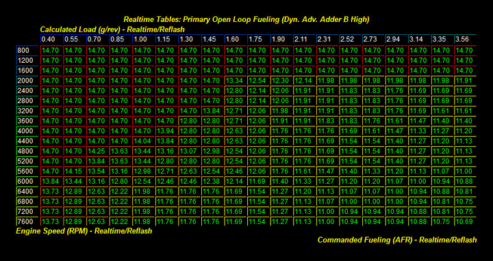

Ex: Primary Open Loop Fueling table from a 2011 STi using Injector Dynamics ID1000 injectors and COBB Tuning SF Intake system. Thanks to accurate characterization data for the injector and intake hardware changes, the Open Loop Fueling table is a close representation of the actual air-/fuel ratio and allows for open loop fueling to be easily adjusted as the calibrator desires.
The turbo EJ engine tends to require a richer air-/fuel ratio than other common turbocharged engines in order to control detonation and temperatures. On 91-93 octane fuels, air/fuel ratios ranging from 10.8-11.5, respectively, tend to provide the best blend of combustion efficiency and detonation resistance. Outside of this range, it is uncommon to observe significant power gains with leaner mixtures, and rich misfiring can occur with richer mixtures. Always begin with an overly rich air-/fuel ratio, and then slowly remove fueling until the desired fueling is achieved. This process will also help identify the point at which power is measurably increased as the mixture is made leaner, or when power is unaffected from a leaner mixture. Close observation must be paid to all knock monitors as outlined in previous sections when adjusting the air-/fuel ratio on pump gas as the threshold for detonation on pump gas can be abrupt and bear harsh repercussions.
For Stage1 and Stage2 vehicles operating near sea level, close attention should be paid to the overall injector duty cycle. The factory injectors "go static", meaning the injector coil no longer has adequate time to discharge between cycles, at approximately 95% IDC. If mechanical boost creep forces the fuel system beyond its limits, an alternate solution to reduce boost or an increase fuel system capability capacity must be found in order for a consistent and safe calibration to be completed. 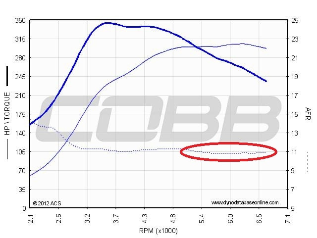

Ex: This Stage2 2011 STi is demonstrating signs that its stock injectors are being pushed beyond their controllable limits. The highlighted enrichment at higher RPM is not due to a tuning choice, but rather the lack of coil discharge time between cycles at IDC is pushed beyond 95%. While enough fuel is available to achieve suitable AFR under these conditions, if fueling demand is further increased under other circumstances, such as cooler weather or much higher boost levels, a dangerous lean condition will result.
...
- Rev Limit (Fuel Cut) Primary Fuel Resume (Max. Boost) [ALL 2.5L MODELS]: When the rev limit fuel cut is enabled and RPM drops below the threshold necessary to resume fuel, fueling will not resume until boost also drops below this table's threshold. When using LC and FFS, this limiter can cause a delay in the re-enabling of normal engine operation during or following the launch or shift.
...
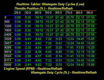
- Wastegate Duty Cycles (Low)(Off-Idle) [02-05 WRX]: Wastegate duty is initially set to this value when leaving idle mode. Idle mode is determined by the throttle position. The "Wastegate Duty Cycles Compensation..." tables do NOT impact this value.
| Anchor | ||||
|---|---|---|---|---|
|
From the factory, most all of the Subaru factory turbochargers are equipped with 7-10psi wastegate actuators, meaning the mechanical minimum for boost pressure is 7-10psi when input energy is enough to create that much (or more) boost. While this is also a minimum, it is expected to also set the cap for maximum boost levels generated when the boost control system is disabled. The internal wastegate port area of the turbocharger is engineered to provide adequate flow with stock exhaust systems at stock power levels while keeping spool-up quick and predictable. A significant limitation of this wastegate area is encountered with the greatly increased coldside cold side and hotside hot side airflow capabilities through the turbocharger that are is created by upgraded downpipes, catback exhausts, intake systems, etc. By definition, mechanical boost creep is the forceful overrunning of the turbocharger due to the wastegate's inability to relieve exhaust gases from the turbine housing – without a complimentary increase in airflow through the wastegate area, it is unable to relieve/bypass enough exhaust gasses to keep boost levels limited to the actuator's spring pressure.
This phenomenon is most prevalent on stock turbocharger vehicles with upgraded turboback exhaust and intake components, especially those that remove normal "restrictions", such as those that delete all catalysts or muffling devices. "Favorable" environmental conditions, such as low ambient temperatures and high barometric pressures, worsen the situation – in the US, boost creep is most problematic in the low-lying cool coastal Northwest and Northeast regions. Periods of high exhaust gas temperature and heavy load will tend to exacerbates exacerbate the situation, such as when going WOT in 5th or 6th gear or while climbing a long hill under power.
...
- Installation of an external wastegate system
- Removal of aftermarket parts such as intake or downpipe
- Porting and polishing of the internal wastegate area of the turbine housing
- Throttle position tuning to limit boost at higher RPM
- Fuel system upgrades to ensure adequate fueling under creep conditions
- Increase octane to raise the detonation threshold (race gas, E85, etc.)
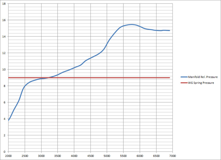

Ex: This Stage2 STi demonstrated a significant amount of boost creep during dyno tuning conditions. Boost in PSI is the Y-axis, RPM is the X-Axis. This datalog was taken with the boost control system disabled; the red line has been added to demonstrate the boost curve expected if the wastegate system was working correctly. This vehicle's boost control system was completely ineffective past 4000 RPM, with boost levels peaking at ~15.5psi at ~5600 RPM. Should conditions change and the detonation threshold become becomes greatly reduced, this vehicle will have no mechanical authority to reduce the boost to keep knock under control. The possible result? Boom.
...
Adjusting the Boost Targets table is a straight-forward procedure. From the factory, the target values scale from lowest (left columns) to highest (right columns), a style that can easily be mimicked while performance tuning. Using the interpolation functions (vertical and horizontal) facilitates shaping a linear targets table from lower to higher throttle positions and across the practical RPM range of the engine. In general, it is recommended to review the factory and OTS mapping Boost Targets tables for your particular application, and then reshape the higher throttle areas of the table as necessary. Boost Targets tuning at low throttle positions will have negligible/zero impact on actual boost response and control.
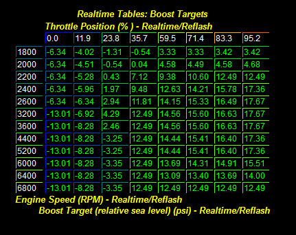
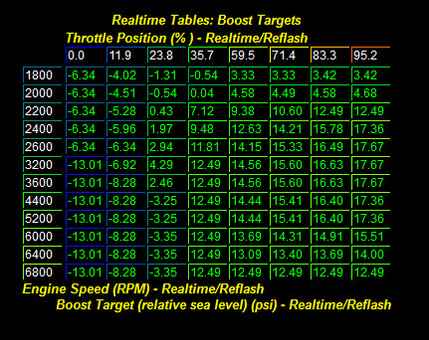
Ex: Target boost table for a Stage2 2006 STi. Note that Boost Targets are similar to stock at lower throttle positions and use higher boost targets at higher throttle positions. Boost Targets are kept low (12.49psi) at higher RPM to account for the turbocharger's naturally decreasing boost output (it cannot hold flat boost to redline) and help alleviate the burden carried by stock fuel injectors that are at their power limits. "Actual" boost was observed to be 17.5psi peak, tapering to 12psi at redline, during a WOT dyno run.
...
Generally accepted tuning practice suggests always beginning with each table set to full zeros in order to determine the mechanical minimum boost level, as well as potentially identify any anomalies with the boost control system, such as an uncontrollable mechanical boost creep or a failing wastegate door actuator. This will also facilitate a constant and repeatable boost curve while working on other areas of the tune, such as ignition advance and open loop fueling.
It can sometimes be helpful to use very large WGDC values at low RPM where full boost cannot be achieved. This will help reduce spool-up times, though only by a small margin.
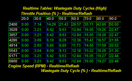


Ex: Wastegate Duty Cycles (High) and (Low) tables from 2006 STi equipped with 18G turbocharger, external wastegate and 3-port boost control solenoid. Note that the values used to achieve targeted boost levels are much smaller than the factory, which is a result of the large hardware changes to the boost control system. This WGDC resulted in a flat ~18psi boost curve (14.5psi default spring pressure).
...
The Turbo Dynamics system is an elaborate but elegant system for controlling the wastegate duty cycle in order to achieve the targeted boost values when mechanical conditions allow for it. Practically speaking, the system is the Proportional and Integral (P+I) components of a full full "PID" http://en.wikipedia.org/wiki/PID_controller system, meaning it features multiple levels of feedback controls and response sizes but does not utilize a predictive component. Adjustments to the Turbo Dynamics tables are primarily spurred by mechanical changes to the boost control system, such as to the boost control solenoid or when an external wastegate system has been fitted to the vehicle.
...