
9C1760 - COBB R35 GT-R Lowering Springs
09-12 GT-R
Congratulations on your purchase of the COBB Tuning GT-R Lowering Springs! The following instructions will assist you through the installation process. Please read them BEFORE beginning the install to familiarize yourself with the steps and tools needed. If you feel you cannot properly perform this installation, we HIGHLY recommend you take the vehicle to a qualified and experienced automotive technician.
Table of Contents
| Table of Contents |
|---|
Parts List
- Front Progressive Spring Set
- Rear Progressive Spring Set
Tools Needed
- Phillips head screwdriver screwdriver
- Flathead screwdriver
3/8" ratchet
3/8" 10mm deep socket
3/8" 12mm deep socket
- 3/8" 14mm deep socket
- 3/8" 17mm deep socket
14mm combination wrench
- 17mm combination wrench
17mm O-ratchet or specialty "notched" Socket
Deadblow Hammer
- Torque Wrench
- Trim removal tool
3/8" 12" extension
3/8" 6" extension
Front Spring Removal
- Securely raise or lift the vehicle
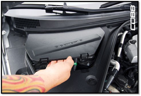
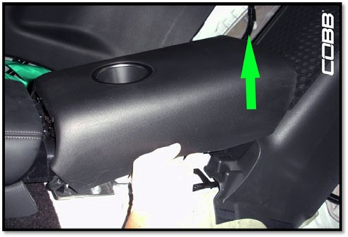
- Remove the battery cover.
- Using a trim tool, remove the five plastic fasteners that hold the trim surrounding the battery.
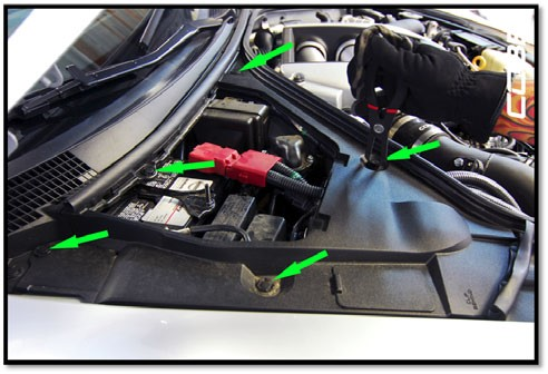
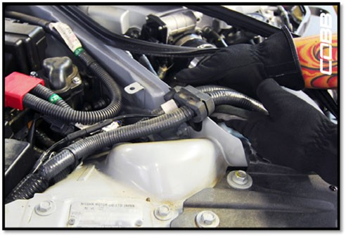
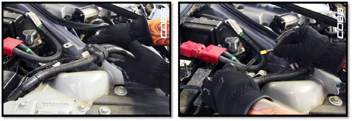
- Lift the plastic surround and move it out of the way to access the electronic damper connector.
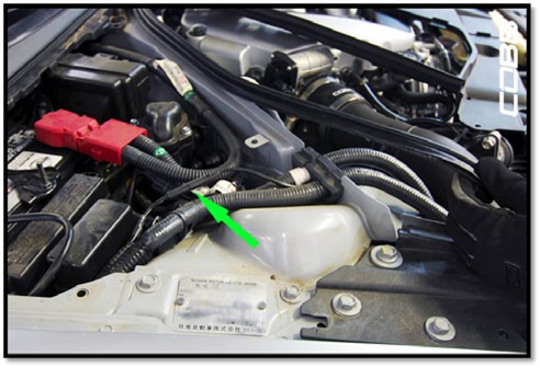
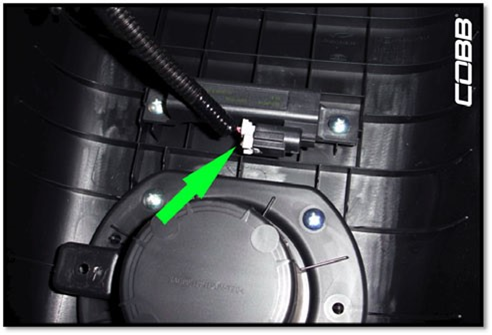
- Using a small flat screwdriver, carefully disconnect the damper connector making sure not to damage the clip.
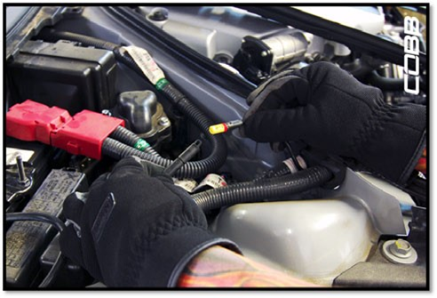
- Remove the damper wire from the rubber grommet that holds the harnesses and damper wire in place.
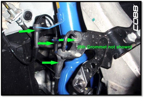
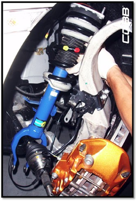
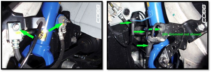
- Proceed into the wheel-well area and remove the speed sensor wire from the shock body. (It should be held in place by five (5) rubber grommets as shown in the picture below).
- Next, remove the two (2) 12mm flange nuts and one (1) 12mm flange bolt that hold the brake line to the shock body brackets.
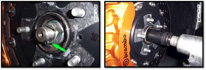
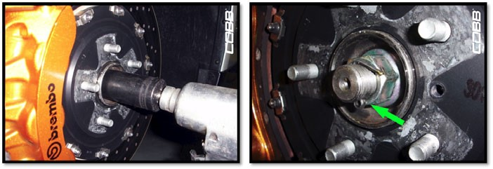
- Remove the cotter pin from the end of the axle and remove the 32mm axle nut.
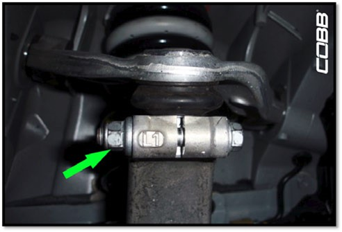
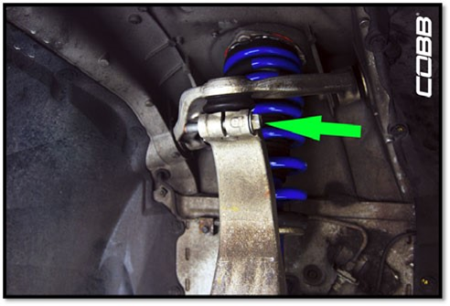
- Remove the 17mm nut and 17mm bolt from the lower control arm.
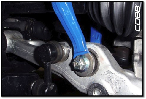
- Remove the 14mm flange nut and flange bolt that secures the ball joint and separate the upper control arm from the upright.
- With the upper control arm free from the upright, start pivoting the entire assembly outwards (away from the vehicle) WHILE tapping the axle with a soft-faced mallet to free it from the hub assembly.With the upper control arm free from the upright, start pivoting the entire assembly outwards (away from the vehicle) WHILE tapping the axle with a soft faced mallet to free it from the hub assembly.
**NOTE: Make sure not to pull or stretch the CV Boots while working on the axle as it can rip, or the joint(s) may separate internally.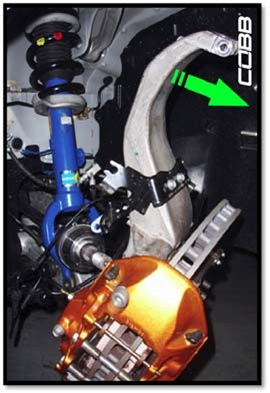
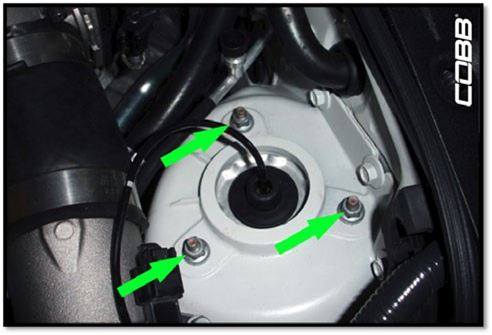
- Now you can go back to the top of the strut (inside the engine bay) and remove the three 12mm flange nuts to completely free the strut assembly.

- Carefully pivot the axle out of the way and you should now be able to pull the entire shock assembly out of the vehicle.
- Now go ahead and repeat steps 2 through 14 for the opposite side.
Front Strut Disassembly and Reassembly
NOTE: The factory springs do not have a great amount of preload, however it might be a good idea to use a spring compressor for precautionary reasons.
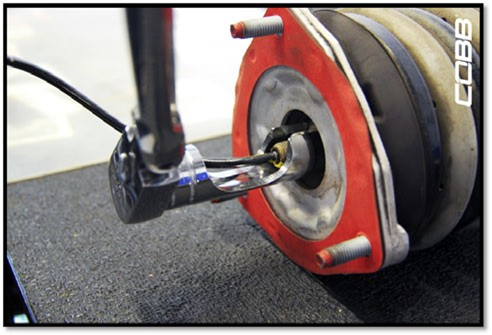
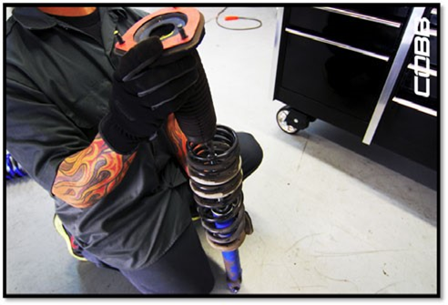
- With the shock assembly out of the vehicle, carefully remove the rubber cover using a flat head screwdriver to expose the 17mm flange nut.
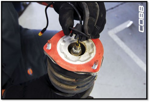
- Remove the 17mm flange nut using either an O-Ratchet or a specialty “notched” socket to allow the damper wire to pass through the tool.
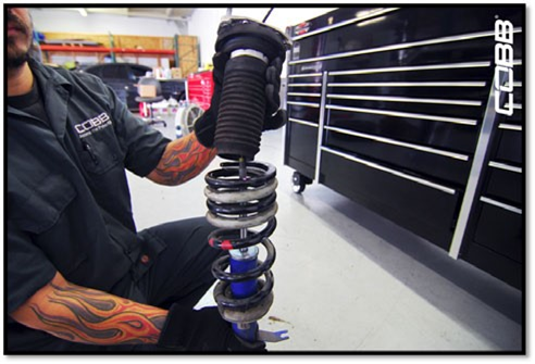
- With the 17mm flange nut removed, carefully remove the entire top hat along with the dust boot. Continue by removing the original springs while noting its orientation.
- REPEAT STEPS 1-3 for the opposite side.
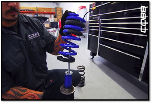
- Reassemble the strut assembly using the new COBB springs in reverse order from the steps above. Once together torque the flange nut (holding the assembly together) to 44 ft/lbs
Front Strut Assembly Installation
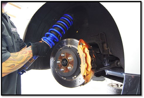
- Slide the entire assembled shock assembly back into the vehicle in reverse order from the steps above.
NOTE: Carefully maneuver the shock assembly around the axle to prevent damage to the CV Boots.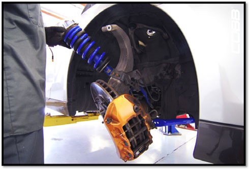
- Tighten the top hat 12mm flange nuts to 28 ft/lbs.
- Re-install the upper control arm ball joint to the upright with the 14mm flange nut and flange bolt and torque to 41 ft/lbs.
- Re-install the 17mm nut and 17mm bolt on the lower control arm and torque them to 79 ft/lbs.

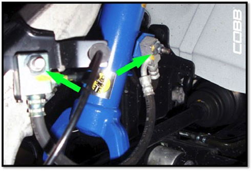
- Re-install 32mm axle nut and torque to 166 ft/lbs and re-install the axle nut cotter pin (green arrow).
- Re-install the brake line to the shock body brackets using the 12mm flange nuts and torque them to 16 ft/lbs and re-clip the speed sensor wire firmly in place.
- Fish the damper connector wire through the rubber grommet, and firmly reconnect it.
- Re-install the plastic surround using the 5 plastic fasteners
- Replace the battery cover.
- Repeat steps for opposite side.
Rear Interior Removal
- Accessing the top three (3) flange nuts that secure the rear shock assembly top hats to the chassis will require removal of the majority of the rear seat and interior panels.
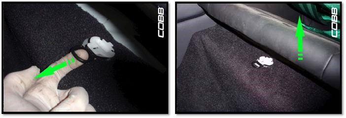
- Start by pulling the loop to release the lower seat cushion and pull the cushion completely out
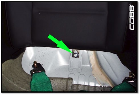
- Remove the 14mm flange nut that secures the rear upper seat cushion. Once removed, pull the cushion away from the car and up to release the cushion from the top latches.
- Repeat for opposite side.
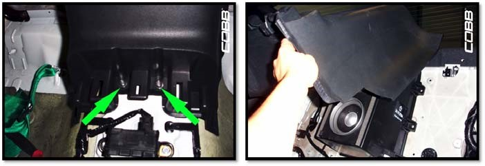
- Remove the rear cup holder center console by firmly pulling up. It is only held on by some push clips.
- As you lift the rear cup holder center console, you will notice there is a harness attached to it. Flip the entire console over and disconnect the harness.
- Remove two (2) 10mm flange bolts that secure the bottom of the rear speaker enclosure and pull the entire surround out.
- Next are the lower side panels. To remove these, we first need to unfasten the following plastic push clip holding the front of the panel to the chassis.
- Lift the inside plastic door sill trim just enough to allow clearance for the lower side panel to come out. In addition, separate the rubber door seal.
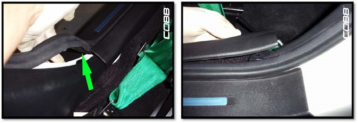
- The lower side panel should now come out by firmly pulling on it. It should only be held in place with push clips at this point
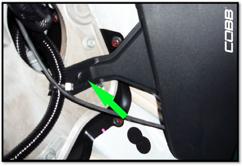
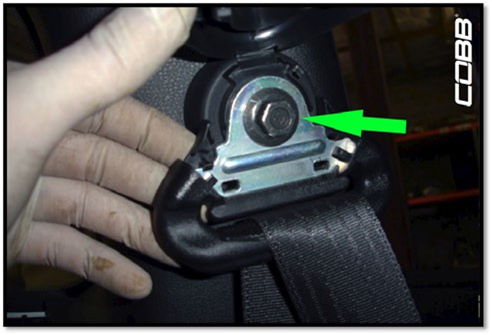
- Carefully pry off the plastic cover on the seatbelt loop with the trim tool to expose the 14mm flange bolt that secures it to the chassis and remove it.
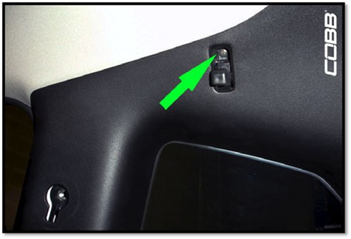
- Flip the hanger hooks down to expose a hidden bolt and remove it using a Phillips head screwdriver.
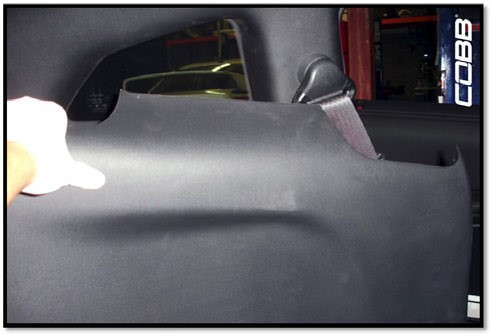
- The upper side panel should now come out if you firmly pull on it since it is only held with push clips at this point.
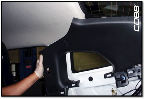
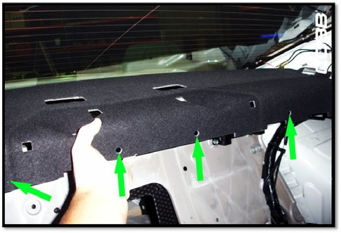
- The last interior piece is the rear deck cover. Note the four plastic fasteners along the front edge and remove them. This will free the deck cover and allow it to be pulled out.
Rear Shock Assembly Removal & Assembly
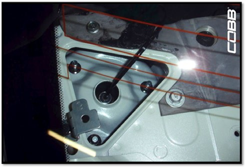
- With the interior removed, note the location of the rear top hat flange nuts as well as the damper wire connector. Using a small flat head screwdriver disconnect the damper connector making sure not to damage the connector clip.
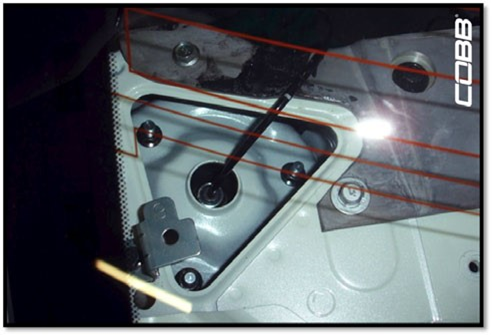
- Remove the three 12mm flange nuts that secure the shock assembly top hats to the chassis.
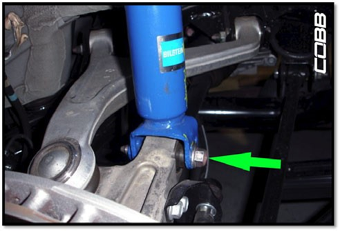
- Proceed into the wheel-well area and remove the 17mm flange bolt from the bottom of the shock assembly.
- Remove the entire shock assembly.
NOTE: Pay close attention to the damper connector wire and make sure it doesn’t get snagged on anything on the way out.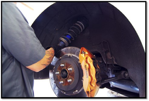
- With the shock assembly out of the vehicle, remove the 17mm flange nut using either an O-ratchet or specialty "notched" socket to allow the damper wire to pass through the tool.
NOTE: The factory springs do not have a great amount of preload. However it might be a good idea to use a spring compressor for precautionary reasons.

- With the 17mm flange nut removed, carefully remove the entire top hat along with the dust boot. Continue by removing the original springs while noting its orientation.
- Install the new COBB springs in the reverse order from above.
- With the rear shock assembly back together, torque the 17mm flange nut to 44 ft/lbs
- Repeat for the opposite side.
Rear Shock Assembly Installation
- Slide the entire assembled shock assembly back into the vehicle in reverse order from the steps above. NOTE: Make sure to pass the damper connector wire through the chassis opening.
- With the help of another person, re-install the three (3) 12mm flange nuts that secure the top hat to the chassis and torque them to 29 ft/lbs.
NOTE: Don’t forget to reconnect the damper connector wire.
- Re-install the 17mm flange bolt at the bottom of the shock assembly and torque it to 55 ft/lbs

- Repeat for the other side, and reinstall interior in the reverse order of removal.

| Insert excerpt | ||||||
|---|---|---|---|---|---|---|
|