Volkswagen Mk6 Tuning Guide
Getting to know the Mk6 VW 2.0T
Here we will go over a few of the basic details and terminologies that are specific to VW 2.0T before we begin tuning on a COBB Accessport equipped Volkswagen.
- Airflow Based – Volkswagen uses a MAF and MAP based airflow system. Unlike many solely MAP based systems, the VW platform is also equipped with a MAF sensor that is utilized in parts of the logic, mostly for modeling and checks and balances in the fueling and load algorithms. The VW 2.0T utilizes a manifold absolute pressure (MAP) sensor located in the intake manifold to measure the mass of air entering the engine. Changes to the intake (MAF housing diameter) configuration will require tuning and heavily contaminated air filters of both OEM and aftermarket construction were found to reduce power output at moderate to high engine speeds. Frequent air filter cleaning and/or replacement is recommended for best performance and engine protection.
- MAF System – While the MAF system is not solely used as primary load calculations, it must be kept properly calibrated. Any changes to the intake system will require the MAF scaling to be adjusted accordingly.
- Fuel Control – The VW 2.0T operates in a constant closed-loop state, constantly utilizing the A/F values in its tables and making adjustments via its equipped wide-band O2 sensor.
- Boost Control – The VW 2.0T does not directly target boost, but rather engine load. Engine load is calculated based on numerous variables such as: pedal position, air flow, boost and RPM. Engine load is converted to a requested torque, the ECU then uses a dynamic boost level to achieve its requested torque.
- Ignition Control – The VW 2.0T has an incredibly complex timing strategy. It allows for individual timing corrections per cylinder per event. The Accessport allows you to monitor each cylinders knock events.
**After flashing a calibration to the ECU, it is not uncommon for a rough start (Aprox 15-30 sec.) as the ECU's learned adaptive's have been reset during the flash process**
Commonly Used Acronyms
|
|
The Tuning Guide
This tuning guide is broken into the basic components of tuning the VW 2.0t and the tables associated with each of these components. For each major tuning category, the guide outlines basic tuning strategies and defines tables within this category (for example: Boost Control, Fueling, and Ignition Timing). Table descriptions and tips will follow the basic tuning strategies below.
Step 1 – What is the mechanical configuration of the vehicle?
The first step in tuning is choosing a COBB Tuning Off-The-Shelf (OTS) calibration that most closely matches the mechanical components and modifications of the vehicle to be tuned.
The Stage1 calibrations are designed for vehicles with a stock or axle-back exhaust system. The Stage1 COBB mapping was designed with optimized ignition, boost, and fuel targets for enhanced performance and responsiveness on a vehicle with mainly stock hardware.
The Stage1+ calibrations are designed for vehicles equipped with upgraded air intake system with a stock or axle-back exhaust system. The Stage1+ COBB mapping was designed with optimized ignition, boost, and fuel targets for enhanced performance and responsiveness on vehicles with upgraded intake hardware.
The Stage2 mapping is designed for vehicles equipped with turbo back high flow exhaust and upgraded air intake systems. The Stage2 COBB mapping was designed with optimized ignition, boost, and fuel targets for enhanced performance and responsiveness on vehicles with upgraded intake hardware and a full exhaust system.
Step 2 – What fuel is the vehicle using?
Please note that COBB Tuning offers calibrations for two different fuels: 93 octane (98 RON), 91 octane (95 RON) / ACN91 (91 octane from Arizona, California, or Nevada). If your fuel does not meet the standard of the available COBB maps you will need to adjust the calibration accordingly. Take a moment to compare and contrast timing, boost, and ignition tables from each type of calibration. Higher octane fuels support more ignition timing, higher boost levels, and leaner air to fuel mixtures compared to lower octane. Using a map designed for high-octane with low-octane fuels can produce engine damage.
Step 3 – What type of air intake is on the vehicle?
The VW 2.0t utilizes a manifold absolute pressure (MAP) sensor as one way to measure the mass of air entering the engine. Filter element configuration does not necessarily require tuning but heavily contaminated air filters of both OEM and aftermarket construction were found to reduce power output at moderate to high engine speeds. (Changes to MAF housing diameter will require calibration) Frequent air filter cleaning and/or replacement is recommended for best performance and engine protection.
Preparing to calibrate the vehicle
Connect the Accesstuner software to the Accessport equipped VW 2.0t
Open the selected starting point calibration in the Accesstuner software. Configure the Accesstuner software to connect to your vehicle. Attach the OBDII cable to the vehicle and the associated USB to the computer and Accessport. Press "Ctrl+F" to configure the program. Select the directory in which to store your data logs under the "logging" tab. 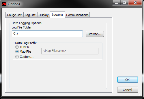
Display and Log critical engine parameters while testing
Accesstuner software allows the user to visualize, sample and record critical engine parameters including sensor information and commanded engine function.
To setup displayed parameters on the live "Dashboard" press "Ctrl+F" to configure the logged parameters in the "Log List" tab, and those displayed in the Accesstuner "Dashboard" through the "Gauge List" tab. The Dashboard, a screen that reports active engine and sensor parameters, can be accessed by pressing "Ctrl+B." It is critical to actively monitor the condition of the motor during tuning and this screen is the single best way to do so. These data monitors allow the tuner to determine if a calibration is performing correctly. Accurate and deliberate assessment of logged parameters is the only way to avoid conditions that may damage the motor.
Hint: Configure recorded parameters in the "Log List" tab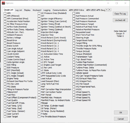
While connected to a running vehicle press "Ctrl+F" and select the "Log List" tab to select the parameters displayed in saved Accesstuner logs. When data logging is enabled (Ctrl-D) these parameters will be permanently written to a comma delimited data file.
Note: More than 45 parameters can be selected at any one time! The rate of data collection will be lower than optimal when more parameters are selected. For example, you could see a higher sample rate with 12 parameters than 20 parameters.
This is a screen shot of some of the available parameters to display in the live dashboard gauges (Gauge List tab) or to be recorded in the data log file (Log List tab). The most up to date list of monitors is always available here.
Below is a list of recommended parameters for the VW 2.0t. The selected parameters are those that are critical to record under most conditions. Other parameters may be selected or removed based upon the objectives of any specific tuning process.
AFR - The lambda reading taken from the internal wide-band oxygen sensor.
AFR Commanded (Final) - The lambda request from the ECU after compensations.
Accelerator Pedal Position - The percent of pedal movement at the driver's
Boost Pressure - Gauge Pressure readings from MAP sensor. (This monitor only displays pressure values. See: Manifold Abs. Pressure for related vacuum readings)
ETC Angle (Actual) - Current throttle blade position as reported by the ETC sensor.
ETC Angle (Target) - ECU's desired throttle angle.
Ignition Timing (Final) - Final ignition timing after all correction and adjustments in degrees before TDC.
Knock Retard Cyl. 1-4 Knock Retard for cylinder 1-4
IAT - Intake air temperature.
Load Actual - Current Load value. ( This is the data the ECU will use for axis look-ups)
Load Request (MAX) - This is the ECU's maximum engine load value, not a target.
Long Term Fuel Trim - Long term fuel trims displayed in percent.
MAF - Mass air flow.
RPM - Engine speed.
Rail Pressure Actual - Current fuel rail pressure.
Rail Pressure Commanded - Requested rail pressure.
Short Term Fuel Trim - Short term fuel trims.
Tumble Flap Position - Current tumble flap position.
Tumble Flap Position (Commanded) - Requested tumble flap position
WGDC - Current waste-gate duty cycle.
WGDC Target (Modeled) - Target modeled waste-gate duty cycle.
Note: Timing corrections:
Negative timing corrections should remain as minimal as possible. When logging all cylinders corrections under full throttle, consistent negative corrections across multiple cylinders or incremental corrections indicate excessive engine noise and is a sign that the map might be too aggressive for the mechanical condition of your vehicle.
Fuel trims refer to adjustments being made by the ECU dynamically to the base fuel table to get the proper air fuel ratio. Short term fuel trim refers to adjustments being made in response to temporary conditions. Long term fuel trims are used to compensate for issues that seem to be present over a longer period. Fuel trims are expressed in percentages; a positive value indicates lean (ECUis adding fuel) and negative values indicate rich (ECUis subtracting fuel). Fuel trims are generally calculated by using a wide set of data values, including pre-cat O2 sensors, intake air temperature/pressure, ECT, knock sensors, engine load, throttle position, and even battery voltage can effect fuel trim. Long term fuel trims generally should not exceed +- ~7-10%, while short term trims at idle ideally should be in the +- 3% range. Ideally both should be within ~3-5%.
Calibration Refinement (Using a Load-Based Chassis Dynamometer)
Important! - Current OTS maps have Launch Control (LC) enabled in them. The COBB LC system uses rear wheel speed to activate the system. In order to run the car on a 2wd dyno you need to turn the LC Master Switch to OFF (0).
A: Perform initial testing at lower boost
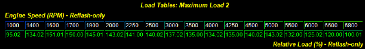
After choosing the most appropriate starting point calibration, prepare to test and refine the calibration on a load-based chassis dynamometer. When creating a custom tune, it is best to begin testing under low load (boost) conditions by lowering values in the "Maximum Load 1, Maximum Load 2 " tables. This lowers the requested load (boost). Testing done at lower boost will allow you to assess the calibration without putting the motor under potentially dangerous conditions. Start the tuning process by loading this "low boost" starting point calibration onto the vehicle.
B: Increasing load target to attain greater boost
The Volkswagen 2.0t is a "Load Target" based system, meaning it uses a complex routine to reference multiple tables based on conditions (Barometric pressure, Atmospheric Temp, Current Knock Condition, Coolant Temp, Charge Air Temp. Etc.) to achieve its target load utilizing a dynamic boost level.
The Target boost is derived directly from the Target Cylinder Filling, and based on modeling, however it is possible to scale the final target boost value by using a table originally meant to correct for cylinder filling based on the angle the inlet valves are closing. The table "Target Boost Scaling", will have a direct effect on the target boost value and keep the PID system working as intend as long as the ECU can still read the current boost level. Small changes (.05) will have an effect of 1-2psi.
There are many limits and targets surrounding load and these are what are typically manipulated in order increase HP and TQ. The main (both cruise and WOT) control for the boost system is the "Target Cylinder Filling" table. This table is the ceiling or maximum allowable requested load. Even if "Maximum Load 1, Maximum Load 2" are raised above the values in "Target Cylinder Filling" it will be limited to the values in "Target Cylinder Filling". Making sure our targets in "Maximum Load 1, Maximum Load 2 " are below "Target Cylinder Filling" we will raise the maximum load values to increase boost as we begin tuning.
Making large changes in the low load cruise areas of this table that are not also modified in the corresponding area of the "Optimum Engine Torque" table can cause undesired affects. The map "Target Cylinder Filling" is the inverse of map "Optimum Engine Torque" in the load calculation function (it is understood that this is not a direct arithmetic inverse, but is intended to mean that the functions on the x, y & z axes are complementary).
In order to gain understating of the ECU's's current operation we should monitor "Load Actual" (to determine actual engine load), "Load Request (Max)" (to determine what the ECU is targeting from the base table data) . The ECU will not always hit its load target ceiling, so some deviation between "Load Request (Max)" and "Load Actual" is not uncommon or necessarily sign of problems.
An important thing to understand is the ECU will run the lowest load being requested or limited, also, these load values are a ceilings not a true "target" but a limit.
The turbocharger boost levels are the main variable used to create torque. When you increase your load targets, you will see the ECU uses more Waste-gate Duty (%) in order to achieve the higher torque (boost) levels. Increasing load target values will allow the vehicle to create more boost (within the systems limits) as long as the limit tables are raised.
Associated Limits Tables:
(Other limit values may have to be adjusted depending on vehicle modifications and desired results)
Boost Pressure Limitation:
Maximum Allowed Pressure ratio for Turbocharger: Boost pressure control upper limit (maximum compressor pressure ratio)
Maximum Load (LBK Position) 1: Maximum Load dependent on LBK position.
Maximum Load (LBK Position) 2: Maximum Load dependent on LBK position.
Maximum Load correction (Engine Temp): Load correction for engine operating temperature.
Maximum Relative Load (Overboost Error): Maximum allowable cylinder charge.
Warnings
Without any mechanical changes to the stock boost control system it is possible to achieve boost levels at the edge of the stock turbocharger capacity. At sea level, aggressive tuning using the stock boost control system can achieve 21.5+ psi mid-range and more than 14psi at redline.
C: WGDC System
The VW 2.0t uses an algorithmic base to calculate duty cycles using a number of modeled airflow look ups as well as atmospheric and conditional inputs.
Using the Isentropic Efficiency Compressor map, Isentropic Efficiency Turbine data, along with the Turbine Mass Flow that is calculated from the pressure ratio information, the exhaust mass flow is calculated. Next, utilizing the exhaust mass flow in the wastegate Canister Pressure target map, along with the current gear (y-axis) the target wastegate Canister Pressure is calculated. The Target wastegate canister pressure is then divided by target pre-throttle pressure to arrive at wastegate can target pressure ratio. This is the Y-axis in wastegate Duty Cycle Output Table, the x-axis is the pre-throttle target boost pressure. This is the Base wastegate duty cycle before corrections.
Below you will find a diagram to visualize the logic flow of the WGDC system calculations:

D: Tuning for appropriate Air to Fuel ratios
The ideal air to fuel ratio depends upon fuel quality. Higher octane fuels are more detonation resistant and therefore can be run at leaner air to fuel ratios. Leaner Air to Fuel ratios produce higher power but also create more heat. Excessive heat can lead to detonation. Lower octane fuels such as 91 octane or 95 RON are more prone to detonation and therefor require a richer air to fuel ratio. Rich air to fuel ratio combustion produces less heat and therefore less detonation. Several tables directly impact fueling ratios in these cars. "Driver Fuel Target", "Lambda for Component Protection" and "Lambda for Component Protection with Tumble flaps open" are the primary tables dictating fuel mixtures.The tables are referenced by Load and Engine Speed. These are target tables; they are used by the ECU to set the desired AFR.
The VW 2.0t utilizes internal wide-band oxygen sensors to monitor fuel mixtures. The sensor is located in the down pipe. As a result, the values in the fuel tables are a closed loop target that the ECU will always work to achieve. The active adjustments made by the ECUare displayed in the "Air Fuel Ratio" monitor.
E: Tuning for appropriate Spark Advance
Ignition timing tables - The main tables for ignition timing at WOT are "; "Ignition Timing (Normal) 2". Main timing tables for light load and cruise are "Ignition Tumble Flaps closed 1" and "Ignition Timing with Tumble Flaps closed 2". These tables are referenced by Load and Engine Speed. Logging these parameters will allow you to reference the specific regions of these tables that may need to be edited to produce optimized ignition timing.
The ECU primary will run in "Ignition Timing (Normal) 2" under full load conditions. The ECU will blend between the two tables briefly during wot transitions depending on cam angle.
Timing adjustments are currently limited to .75 degree increments.
Detonation based timing adjustment - Ignition timing is also adjusted in response to detonation or pre-ignition. The ECU actively reduces timing in response to detonation. The ECU has the capability to make individual cylinder timing adjustments, because of this monitoring a single cylinders timing correction will not result a global picture of engine operations. Timing adjustments in response to detonation are logged with the "Knock Retard 1-4" monitors. Each knock event results in a change of .75 degree increments depending on severity of the event.
Generally speaking, higher ignition timing supports higher torque and greater power. However, ignition timing should be increased with great caution. Higher timing yields higher cylinder pressures and this is limited by fuel quality and the mechanical limitations of the engine. Too much timing will produce knock correction when fuel quality is limiting. When fuel quality is high, ignition timing should ONLY be added when its addition produces a substantive increase in torque and power. If increased timing does not increase torque the extra cylinder pressure is simply producing unnecessary stress on engine components.
F: Tumble Flaps
The VW 2.0T is equipted with tumble flaps that are individual plates located within the intake manifold runners that can either stay in a flat position to allow maximum airflow or move up to redirect the airflow into the combustion chamber. At
different engine rpms, the tumble flaps are activated to enhance the air/fuel mixture.
The tumble flaps are actuated:
• To improve cold engine idling
• To improve charge efficiency at start-up
• In overrun mode
At other engine speeds, the tumble flaps
are open to eliminate flow resistance and
reduction in engine performance.
Tumble flap adjustments can be found in the "Miscellaneous Tables" folder.
G: Integrating all tuning parameters for the ideal Calibration
The ideal calibration for your VW 2.0t is a combination of all major tuning areas outlined above. Like any performance vehicle, the VW 2.0t will make the most power when run lean with the maximum amount of ignition timing that the ECU will allow without detonating. However, this ideal of 12.5:1 air to fuel ratio and high ignition timing is not realistic for most configurations and fuels in forced induction vehicles. The only way to determine if a calibration is ideal is to run the car on a load-based chassis dynamometer where the impact of calibration changes is easily measured. For example, addition of ignition timing that does not result in increased torque is a not ideal. If additional timing does not create power then you are simply adding stress to the engine components without tangible benefit. The same is true of boost and air to fuel ratio. If you can run the vehicle at a richer air to fuel ratio without losing power this is more ideal than running the car lean. If increasing boost does not yield considerable power gains the turbo may simply be out of its efficiency range. In this scenario less boost may produce more power. To get a coarse idea of how the ideal tune looks on your fuel type and mechanical configuration, examine the COBB OTS maps and map notes.
H: Precautions
Boost
The stock turbocharger can produce boost levels in excess of 25psi. This boost level can generate enough cylinder pressure to cause engine damage. Be cautious when adjusting boost control parameters. Be particularly cautious when any mechanical component of the boost control system is altered.
Sensor Limits
Engine control is entirely dependent upon accurate readings from the MAP sensor. Even stock vehicles produce sufficient airflow to push these sensors to their limit. Beyond the limits of the stock MAP and MAF sensors the ECU has no way to properly control the engine. Any turbocharger upgrade must also be accompanied by an appropriate MAP and MAF sensor.
Toggles (Switches)
None at this time.
Fuel Injection System
The VW 2.0t utilizes direct injection versus conventional port injection in its turbocharged engines. In direct injection the gasoline is highly pressurized, and injected via a common rail fuel line directly into the combustion chamber of each cylinder, as opposed to conventional multi-point fuel injection that happens in the intake plenum, or cylinder port. This gives the Vw 2.0t many advantages for improved fuel efficiency under light load conditions, and also allowing a leaner Air/Fuel ratio.
The major advantages of the direct injection engine are increased fuel efficiency and higher power output. Gains are achieved by the precise control over the amount of fuel and injection timings that are varied according to the load condition
Fuel Injection Modes:
H01
Homogeneous, 1 injection - single injection during intake stroke
SHX
Start High-Pressure HOM, HSP - single injection during compression stroke
SC1
Catalytic converter heating - single injection during compression stroke
SKX
Catalytic converter heating - Dual pulse fuel injection (compression/power stroke)
HSP
Homogeneous Split Mode - Dual pulse fuel injection (intake/compression stroke)
HKS
Homogeneous knock. (knock conditions) - Dual pulse fuel injection (intake/compression stroke)
HOS
Homogeneous Stratified - Dual pulse fuel injection (intake/compression stroke)
Table Descriptions
See ACCESSTUNER software for available table descriptions.
Aftermarket Map Sensor Scaling
Below you will find how to arrive at the correct values for scaling any map sensor by simply replacing the values for the sensor you wish to install.
Stock Map Sensor:
Minimum pressure = 200mBar/2.9psi
Maximum pressure = 2500mBar/36.26psi
Minimum voltage = 0.4 Volts
Maximum voltage = 4.65 Volts
Map Sensor Gradient = (MAXPRESSURE - MINPRESSURE) / (MAXVOLTAGE - MINVOLTAGE) = 541.18mBar/7.85psi
Map Sensor Offset = MAXPRESSURE - (DSLGRAD * MAXVOLTAGE) = -16.47mBar/-0.24psi
Copyright 2023 © COBB Tuning Products LLC. All Rights Reserved. | www.cobbtuning.com