Subaru Accesstuner DIT Tuning Guide Supplement

![]()
Subaru Accesstuner Tuning Guide Supplement
For Direct Injection Turbo (DIT) Models
INTRODUCTION
This document outlines some of the unique engine control unit (ECU) logic and tuning strategies relevant to Subaru's Direct Injection Turbo (DIT) models. While many of the core tuning concepts for the DIT models will be very similar to the other turbo Subarus, there are some important differences that, if not accounted for, could result in major problems (including potential engine damage). It is not the intention of this document to outline every difference between the DIT and non-DIT ECUs, but rather the most notable differences (known to date) that can impact your ability to tune effectively.
For information about new COBB Custom Feature (CCF) Roms Check out the guide
APPLICABLE SUBARU MODELS
The following Subaru models are applicable to this document:
- 2014 - 2018 Subaru Forester XT
- 2015 - 2021 Subaru WRX
TABLE DESCRIPTIONS
Besides this document, an additional resource for ECU logic details are the table descriptions shown in the Accesstuner software. These will show up in the lower left corner of the software for the current table that is selected. If not visible, make sure the "Table Description" check box is selected in the View menu. Additionally, the Help menu in the software contains links to documents that list all of these table descriptions as well as all of the data monitor descriptions.
CONTACT US
COBB authorized Protuner are welcome to contact us with any additional questions/concerns or when in need of troubleshooting assistance.
FUELING
GLOBAL FUELING ADJUSTMENT FOR E85 OR OTHER ETHANOL CONCENTRATIONS
The following outlines the steps necessary to account for a global fuel adjustment for E85 (or other ethanol concentrations) in your tune. This will also have the effect of modifying your cranking injector pulse width, meaning less tweaking necessary in that area of the tune. WARNING: The compatibility and long-term reliability of higher ethanol concentrations with the factory DIT fuel system components (such as the high pressure fuel pump) is, at the time of this writing, not known.
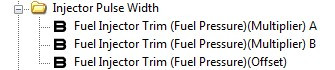
If you want to start by adding 43% more fuel for the global adjustment for E85 (this could be more or less depending on the actual ethanol % in the tank), multiply all the injector pulse width compensation values in each of the three tables below by 1.43 (highlight entire table, hit M key and enter 1.43). From there, if you want to add or remove fuel, repeat this process (ex. +3% = multiply by 1.03, -3% = multiply by 0.97). Note: Fuel Rail Pressure values in these tables must NOT be changed.
- "Fuel Injector Trim (Fuel Pressure)(Multiplier) A"
- "Fuel Injector Trim (Fuel Pressure)(Multiplier) B"
- "Fuel Injector Trim (Fuel Pressure)(Offset)"
- "Fuel Injector Trim (Fuel Pressure)(Multiplier) A"
Note: Some DIT ECUs will only have a single multiplier table ("Fuel Injector Trim (Fuel Pressure)(Multiplier)").
LEAN PRIMARY OL FUELING DUE TO CL FUEL TARGET INTERACTION (AGGRESSIVE START)

There is a specific interaction between the closed loop and open loop fuel targets in the factory logic, that, with particular changes to the tune, can result in an override of the normal open loop fueling with much leaner targets. The "Closed Loop Fueling Target Final (Alternate)(Aggressive Start)(Primary OL Fuel Compare)" table is an alternate final closed loop fueling target that overrides the normal final closed loop fueling target during an entire high throttle run when that run was started with aggressive accelerator pedal movement (i.e. "throttle mash") and when the target called for by this table is richer than what would be dictated by the primary open loop map target (even though it is still in closed loop). In the factory tune, this would only have an effect in closed loop. However, if you modify your tune so that the primary open loop fueling target (as dictated by the Primary Open Loop Fueling tables) is leaner than this table's value (and aggressive start conditions for run are met), when the switch to open loop is made the ECU will set the final primary open loop map target to 14.7:1 AFR and only the "Primary Open Loop Fueling Min. Enrichment" table will come into play. To avoid this, you can do one of the following:
- Set the "Closed Loop Fueling Target Final (Alternate)(Aggressive Start)(Primary OL Fuel Compare)" table to always be leaner than what would be dictated by the primary OL fuel map target (especially in open loop)
OR
- Set the "Closed Loop Fueling Target Final (Alternate)(Aggressive Start)(Primary OL Fuel Compare) Activation (Min. Coolant Temp)" table to its maximum value (ex. 248 deg. F) or set the "Closed Loop Fueling Target Final (Alternate)(Aggressive Start)(Primary OL Fuel Compare) Activation (Max. Coolant Temp)" table to its minimum value (ex. -40 deg.) which will disable the switching all together (in both open and closed loop). As of this writing, our OTS performance maps are set to disable the logic using this method. However, you should confirm this in the tune if you are using an OTS map.
A/F LEARNING #1 LOAD RANGES
Long-term fuel trims (A/F Learning #1) for DIT Subarus are similar in logic to non-DIT Subarus, but there are many more stored values. There are a total of 12 stored A/F Learning #1 trims: 2 at idle (Idle 1 and Idle 2) and 10 applied outside of idle (A1-E1 and A2-E2). The non-idle trims are stored across specific load ranges but there is an RPM breakpoint that determines the split between group 1 (A1-E1) and group 2 (A2-E2) non-idle trims. The same RPM breakpoint also determines the split between the Idle 1 and Idle 2 trims.
A/F LEARNING #1 (GLOBAL ADJUSTMENT) MIN/MAX
![]()
These tables give you the ability to adjust the min/max limits for the global A/F Learning #1 adjustment. This global adjustment can occur after a reset or reflash when specific conditions are met during stable closed loop operation (typically at idle). When the ECU dictates that a global adjustment should occur, all A/F Learning #1 ranges (A1-E1, A2-E2, Idle 1 and Idle 2) are overridden with a current learned trim and then the ECU returns to normal A/F Learning #1 operation. This can cause, for example, fueling changes at WOT that are undesirable (due to this globally applied long-term trim). You can override the allowed global adjustment trims by setting these Min and Max limits to zero (this will set all the trims to zero when the global adjustment is called for). Or if you want to retain the global adjustment, but do not want the higher load ranges to be effected, you can modify the individual A/F Learning #1 load range Min/Max values as described in the next section (this will impact normal A/F Learning trims as well in the ranges modified).
A/F LEARNING #1 INDIVIDUAL LIMITS FOR EACH LOAD RANGE (15+ WRX ONLY)
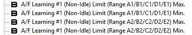
These tables give you the ability to individually determine the minimum and maximum limits for each A/F Learning #1 load range (see A/F LEARNING #1 LOAD RANGES section earlier in this document for details on the load ranges). This allows you to, for example, disable A/F Learning #1 in the higher load ranges so that trims (when in closed loop in that range) are not carried over to your WOT fueling. This also will prevent or allow you to minimize the "global" A/F Learning #1 adjustment in specific load ranges while not disabling the global adjustment entirely (see previous section for more details on the global adjustment). The Min/Max for the A/F Learning #1 Idle 1 and Idle 2 trims can also be adjusted separately from the non-idle limits.
FUEL MODES
The DIT ECU has two primary fueling modes: stratified warm-up (inject fuel during intake and compression strokes) and homogeneous (inject fuel during intake stroke). You will see that the various warm-up and post-start enrichment tables are split across these modes. Stratified warm-up mode is active primarily for a short period of time after engine start except at higher ECTs. Typically, any amount of throttle will cause the switch from stratified to homogeneous fuel mode, so stratified mode is primarily an idle warm-up mode (blipping the throttle at idle will cause a switch from stratified to homogeneous mode and then back to stratified). Homogeneous mode will be active the vast majority of the time. You can determine the current fuel mode by logging/viewing the "Fuel Mode" monitor (1 = homogenous mode, 2 = stratified mode).
Stratified mode can be disabled by un-checking the "Stratified Warm-up Mode" toggle in the "Edit" → "Advanced Parameters" menu of the Accesstuner software (under the "Toggles (Base)" tab) and reflashing the saved map to the car. Note: Not applicable to 15 WRX Post-recall 1 or 14-15 FXT ECUs.
RICH CL TARGET FORCE OPEN LOOP
![]()
When the closed loop fuel target is richer than a specific threshold ("Closed Loop Fueling Target Final Rich Threshold (Switch to OL)" table in the "Fuel Tables" → "Closed Loop Target" group), the ECU will switch to open loop fueling. If you are holding closed loop at higher load in your tune, you may need to adjust this table to avoid an unintentional switch to open loop.
ALTERNATE PRIMARY OL FUEL TARGET AND FORCE OPEN LOOP

At higher load, the ECU may, at times, apply a minimum enrichment that is similar to the factory primary open loop "Base" calibration. This can potentially cause your open loop fueling target to be richer than expected and can also force open loop fueling operation (when this minimum is richer than 14.7:1 AFR) even if the rest of the tune dictates closed loop operation. To eliminate this minimum enrichment and forced open loop from coming into play, set the "Primary Open Loop Fueling Min. Enrichment (Pre-Final)(Force OL) Activation Threshold" table to 65535 (under "Fuel Tables" → "Open Loop (Primary)" table group). Note: Not applicable to 15 WRX Post-recall 1 or 14-15 FXT ECUs.
FORCE FULL-TIME CLOSED LOOP
The following are steps to force the DIT ECU into full-time closed loop. Warning: After making these changes, verify that the ECU remains in closed loop at high load by testing on the car.
- In the "Fuel Tables" → "Closed Loop Target" table group:
- Tune the four "Closed Loop Fueling Target Base (Main)..." A,B,C,D tables and the "Closed Loop Fueling Target Base (Alternate)" table to reflect your desired full-time closed loop fuel targets.
- Set the "Closed Loop Fueling Target Final (Alternate)(Aggressive Start)(Primary OL Fuel Compare) Activation (Max. Coolant Temp)" table to -40 - this disables the "aggressive start" table alternate closed loop target from coming into play.
- Tune the four "Closed Loop Fueling Target Base (Main)..." A,B,C,D tables and the "Closed Loop Fueling Target Base (Alternate)" table to reflect your desired full-time closed loop fuel targets.
In the "Fuel Tables" → "Closed/Open Loop Transition..." → "Delay" table group:
Set the delay values in the "Closed to Open Loop Delays" table to 65535 across the entire table.
- In the "Fuel Tables" → "Closed/Open Loop Transition..." → "Delay Deactivation Thresholds" table group:
- Set all the "Load vs. Rpm Component" raw values (z-axis) of the following tables to zero:
- Closed Loop Delay Max. Load vs. RPM Component Determine (Alternate) - (15+ WRX/16+ FXT only)
- Closed Loop Delay Max. Load vs. RPM Component Determine (Primary Fuel Min. Activation Met)
- Closed Loop Delay Max. Load vs. RPM Component Determine (Primary Fuel Min. Activation NOT Met)
Make sure the "Closed Loop Delay Max. Load vs. RPM Component Threshold (Smoothing Factor 1)" and "...(Smoothing Factor 2)" tables are both set to 65535.
Set all the Engine Speed (RPM) value(s) in the "Closed Loop Delay Max. RPM (Per Gear)" or "Closed Loop Delay Max. RPM" table to 12800.
If you tuned any of the remaining tables in this table group to non-stock values, return these to stock. Failure to do so can cause switching to open loop.
- Set all the "Load vs. Rpm Component" raw values (z-axis) of the following tables to zero:
- In the "Fuel Tables" → "Closed/Open Loop Transition..." → "Transition Thresholds (Alternate)" table group:
- Set the "Closed Loop Fueling Target Final Rich Threshold (Switch to OL)" table to 4.900:1 AFR.
- Set the "Closed Loop Fueling Target Final Rich Threshold (Switch to OL)" table to 4.900:1 AFR.
- In the "Fuel Tables" → "Closed/Open Loop Transition..." → "Transition Thresholds (Delay Active)" table group:
- Set all the Calculated Load (g/rev) values (z-axis) in the "Closed/Open Loop Transition with Delay (Min. Load)" table to their maximum value.
- Set all the Calculated Load (g/rev) values (z-axis) in the "Closed/Open Loop Transition with Delay (Min. Load)" table to their maximum value.
In the "Fuel Tables" → "Open Loop (Primary)" table group:
- Tune the "Primary Open Loop Fueling Base" table(s) as you would normally just in case you have an issue with the car switching to open loop unexpectedly (or if a sensor failure or similar causes full-time open loop failsafe).
- Change the "Primary Open Loop Fueling Min. Enrichment (Pre-Final)(Force OL) Activation Threshold" table to 65535. Note: Not applicable to 15 WRX Post-recall 1 or 14-15 FXT ECUs.
- Tune the "Primary Open Loop Fueling Base" table(s) as you would normally just in case you have an issue with the car switching to open loop unexpectedly (or if a sensor failure or similar causes full-time open loop failsafe).
LIMITS (BOOST/FUEL/LOAD/THROTTLE)
FUEL CUT LIMITER MODES
![]()
![]()
Fuel cut limiters work a little differently for this ECU. There are additional thresholds for each of these limiters that enable a "Mode" that must be active otherwise the fuel cut limiter will not be activated even if the primary fuel cut threshold is exceeded. In the factory tune, these Mode thresholds are set to activate before the fuel cut event would take place. For example, with the rev limiter in the factory tune (15 WRX 6MT), the rev limit Mode will turn on above 6700 RPM and off below 6600 RPM. On the other hand, the fuel cut rev limiter threshold will turn on above 6700 RPM and turn off below 6700 RPM (i.e. basically no hysteresis). The other fuel cut limiter with the Mode requirement is the fuel cut based speed limiter.
WARNING: Failure to account for the Mode activation when changing either of these fuel cut limiters can cause the limiter to be disabled or come in later than expected. The boost limit fuel cut also has a Mode requirement but we've set this up so that you cannot disable this Mode (i.e. when the boost limit fuel cut is called for, fuel cut will always take place).
BOOST LIMITS
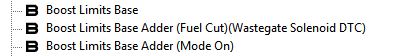
The boost limiter is set up a little differently for the DIT Subarus. The boost level above which fuel will be cut (and P0244 DTC enabled) is calculated as follows:
("Boost Limits Base" table value with all Boost Targets Compensations applied)
+
("Boost Limits Base Adder (Fuel Cut)(Wastegate Solenoid DTC)" table value)
The "Base" threshold is compensated by the same tables that are applied to the "Boost Targets" table and then the "Boost Limits Base Adder (Fuel Cut)(Wastegate Solenoid DTC)" value is added to this to determine the final boost limit threshold for the fuel cut and wastegate solenoid DTC.
As mentioned in the previous section, the fuel cut limiters have specific mode thresholds that must be exceeded in order for the fuel cut to take place. These are typically set up to be a bit lower than the fuel cut thresholds in the factory calibration. These mode thresholds will also dictate a throttle cut for some limiters even before the fuel cut would be enabled. In the case of the boost limiter, it is possible to experience this throttle cut (shown as a partial reduction in Throttle Position) without actually engaging the boost limit fuel cut/DTC (where boost does not exceed the final fuel cut threshold). The boost limit mode threshold is determined as follows:
("Boost Limits Base" table value with all Boost Targets Compensations applied)
+
("Boost Limits Base Adder (Mode On)" table value)
If boost exceeds this at any time (even briefly), the throttle cut will take place until boost drops below this threshold by the amount specified by the "Boost Limits Base Adder (Mode On) Hysteresis" table. If you wish the throttle cut to only be engaged with the fuel cut, you can raise the "Boost Limits Base Adder (Mode On)" table to match the "Boost Limits Base Adder (Fuel Cut)(Wastegate Solenoid DTC)" table in your tune.
You will also notice that there are "Boost Limits Mode On Throttle Cut..." tables. These tables determine the level of pre-defined throttle cut that is chosen based on the current boost level. The throttle limiter cannot be disabled via these tables; only the level of throttle cut will be influenced so the method described in the previous paragraph should be used.
OTHER THROTTLE LIMITS
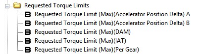
Requested torque (and therefore the throttle target) can potentially be limited to a maximum value based on the dynamic advance multiplier (DAM), intake air temperature (IAT), and other factors via the tables found in the "Throttle Tables" → "Requested Torque Limits" group. To adjust these limiters, simply modify the limit in each of these tables as needed.
WARNING: Using notably different requested torque targets in your tune (as compared to the factory calibration) may cause adverse effects to cruise control operation and potentially other systems.
BOOST/LOAD HARD-CODED LIMITS
The DIT ECU has specific limits as it relates to boost targeting, boost reading, and load. These are hard-coded limits and not a function of any limit table within the ECU. In the future, we plan to modify the factory code to allow higher limits for all three. For now, keep in mind that these values will be capped at what is listed below:
- Boost reading - This is limited to a max of about 24 psig at sea level, not including any potential hardware limit for the factory MAP sensor. We have included the MAP calibration tables to account for the installation of an aftermarket MAP sensor (keep in mind that the factory sensor is a combination unit that also includes the IAT manifold sensor), but even with an aftermarket sensor, the boost reading would still be limited to about 24 psig until the factory code is modified (which we plan to do at a later date).
- Boost Target - This is also limited to a max of about 24 psig at sea level.
- Calculated load - Load is limited to a max of about 3.3 g/rev. For the time being, if you need additional headroom here, you can do the following (WARNING: untested at the time of this writing):
- 1. Decrease MAF calibration table values (airflow g/s) by a specific percentage
- 2. Increase all the "Fuel Injector Trim (Fuel Pressure)..." tables by the same percentage (see "GLOBAL FUELING ADJUSTMENT FOR E85" section for general procedure)
- 3. Decrease all "Cranking Fuel Injector Pulse Width Base..." tables by the same percentage.
- 4. Decrease load values (and airflow if applicable) appropriately for all tables (including manipulating table z-data to retain intended tune) considering the new representation of airflow/load.
KNOCK CONTROL
DAM AND FINE KNOCK LEARNING
With the DIT ECUs, the dynamic advance multiplier (DAM) will be reset to the initial value in your tune ("Dynamic Advance Multiplier (DAM) Reset (Default and Initial Post-Start)" table) on every engine start as long as the DAM did not drop below this value previously. If it did, that lower DAM will persist. Additionally, the fine knock learning table is not necessarily cleared when the DAM changes when driving. The fine knock learning values can persist (and even change) with the change in DAM.
BOOST
OVERBOOST FUNCTION
The factory advertised "overboost" feature, where the DIT motor achieves higher than targeted boost for a period of time, is not a specific function of the ECU but of the factory calibration. For the 15 WRX 6MT, the peak boost target in the calibration is 15.9 psig at sea level (as advertised), but can be a little higher due to the IAT comp (in a moderate range can push peak target up to around 17.x psig). The boost limit fuel cut (and P0244 DTC) is effectively set to around 4 psi above the boost target, which would put it around 20-21.x psig. However, this boost limit must be exceeded continuously for over 2 seconds, so you can certainly see peak boost in that range briefly on the factory tune (or even 22.x psig that some have reported) without engaging the limiter. Pretty much any typical WOT pull will result in the period of "overboost" with the factory tune, but the factory calibration will quickly reduce wgdc when boost gets closer to the boost limit (as well as engage a throttle cut as described in the LIMITS section). At higher altitudes, the peak boost target is lower (just as with prior Subarus) but the "overboost" function in the calibration is still present, so you will still "overboost" relative to the lower target (you just generally won't see the same peak boost as you would at sea level).
In our OTS stage map calibrations for the DIT cars, we get rid of the gimmicky "overboost" calibration and use a specific peak boost target that the tune in not intending to exceed (within normal tolerances). This results in more consistent boost control and the ability to more easily discern an actual overboost condition.
MISCELLANEOUS
"REV HANG" TUNING
![]()
The "Idle Airflow Target Limit (Min)" table (found in the "Idle Control Tables" group) determines a minimum limit to the idle airflow target. This minimum limit is primarily responsible for the "rev hang" effect that can occur between shifts with the 6MT WRX. The idle airflow target is a dynamic value determined by the ECU for normal idle as well as "dashpot" functions (ex. slowing RPM drop on decel). It is used to determine an idle target throttle angle which is added to the main target throttle angle (even outside of idle) to determine the final target throttle angle. Decreasing this table's values, will potentially reduce the idle airflow target (if idle airflow target is less than the given value in this table) and therefore, lowering the idle target throttle angle. This can have the effect of quicker RPM drop on shifts. We have found that leaving the lower RPM portion of the table alone and reducing values in the area where rev hang is an issue seems to work best, but you can certainly experiment to determine what works best for you. You can check out our OTS maps to see how we tuned this table.
PER GEAR IGNITION TIMING COMP - USE 5TH FOR 6TH
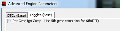
With the factory logic, the per gear ignition timing compensation (as was the case with STis that have this feature) does not allow any compensation in 6th gear. We have added a special toggle, that, when checked, will allow you to use the 5th gear ignition timing compensation also for 6th gear. This toggle can be found in the "Edit" → "Advanced Parameters" menu (Toggles tab) in the Accesstuner software. Note: For CVT models, the per gear ignition compensation (and this toggle) works in the same way except that the gear value is determined as the representative manual mode "gear" whether the tranny is in manual mode or not (and also limited to a max of 6).
MAF/MAP BLENDING AND WOT LEAN CONDITION
![]()
To account for conditions where the MAF sensor is inherently inaccurate (primarily with larger changes in throttle/load), the DIT ECU uses a complex MAF/MAP blending calculation in determining the final MAF value (and therefore load value). The MAF calibration table is always the starting point, but this MAF/MAP blending is done using calculations based in MAP. On the tail end, when the final corrected MAF is being determined, this final "blended" MAP value is converted to MAF via the ideal gas law using VE (determined from the "MAF Corrected Volumetric Efficiency Input..." table(s)), "Intake Temperature Manifold", RPM, and other inputs.
On a car with stock hardware, these VE tables will not generally need to be modified. On cars with engine hardware changes that impact VE (i.e. mods that impact airflow), these tables may need to be tweaked to avoid a WOT fueling issue (typically in a lean direction) that can occur for part or most of the run. The severity of this depends on the extent of the airflow modifications. The issue may also be noticed in some other driving conditions besides WOT.
Note: Some DIT ECUs only use a single VE table.
CVT LAUNCH MODE (15-16 WRX CVT, 14-16 FXT NON-EYESIGHT ONLY)
WARNING: Using the launch mode feature puts more stress on the transmission, drivetrain, engine and other components and can result in increased wear of any of these components as well as the potential for catastrophic failure. The more aggressive driving characteristics that are possible with the launch mode feature could also potentially result in an unexpected loss of vehicle control. This feature should only be used in controlled off-road racing conditions where all parties understand the risks involved.
For CVT cars, a special feature is enabled to allow for more aggressive brake-torque launches and/or to minimize or eliminate performance reduction due to specific throttle closures in other situations. The system is tuneable allowing for different levels of aggressiveness (or can be selectively disabled to retain factory behavior). Even when tuned, the driver still determines when the feature is actually active.
In the factory tune, the transmission control module (TCM) dictates a maximum requested torque during the following conditions that limits the throttle opening and therefore limits boost/torque:
- During staging with a brake-torque launch (i.e. left foot on brake holding car stationary and right foot on gas).
- Briefly after brake-torque launch after vehicle starts moving.
- During "shifts" in Sport # mode.
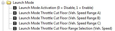
Launch mode for the CVT cars allows you to set a floor to this specific TCM requested torque limiter. This means that, when active, the TCM limit can go no lower than the current floor value in the tune. This allows for a higher potential throttle opening than would otherwise be dictated in the stock tune (when the TCM limiter is lower than the floor value) during the conditions listed above. The floor can also be set to its max which would allow for the potential of wide open throttle (WOT) when active. Or it can be set to zero which disables the floor. Note: other requested torque and throttle-based limits (ex. boost throttle limit) are not impacted by this feature and can still limit throttle.
There are three requested torque floor values across three vehicle speed ranges (named A, B and C). The "Launch Mode Throttle Cut Floor Range Selection (Veh. Speed)" table determines these vehicle speed ranges. For example, if this table is set to 5.0 mph and 25.5 mph, then range A is 0 to <5.0 mph, range B is 5.0 to <25.5 mph, and range C is 25.5+ mph. Generally speaking, Range A would be used for staging (i.e. vehicle stationary) during brake-torque launch. Range B would be used for a period after the launch (when TCM limiter can potentially still come into play). Range C would be used for shifts in Sport # SI-DRIVE mode. Note: Loss of traction from brake-torque launch can cause vehicle speed to briefly read higher than actual, potentially causing the switch to the B range earlier than expected, depending on how this table is set up.
The applied TCM limiter (whether manipulated by the floor value or not) is further compensated by specific intake air temp (IAT) and barometric pressure compensations (not currently exposed in the software). Because of this, the final applied TCM limiter (including the floor value applied if applicable) can be a bit different than the original "base" TCM value (or TCM value with floor applied). This compensation is typically within a range of -10% to +10%, depending on conditions.
You can monitor the activity of the TCM limiter and your launch mode tune via the following two monitors:
- "Requested Torque Limit TCM (Base)" - Base requested torque limit as determined by the transmission control module (TCM) during normal operation. This value is further manipulated by specific compensations to determine a final limit. This monitor shows you what the TCM is intending the base limit to be before any launch mode floor or factory compensations are applied.
- "Requested Torque Limit TCM (Final)" - Final applied requested torque limit as determined by the transmission control module (TCM) during normal operation. This monitor shows the final applied requested torque limit including all compensations and the application of the current launch mode floor (if active).
Even when launch mode is active in the tune, the driver still decides when the potential launch mode floor is applied. This is accomplished by holding the cruise control CANCEL button on the steering wheel when cruise control is OFF (i.e. the cruise control icon on dash is not illuminated). The CANCEL button must be held for as long as the driver wants the launch mode floor to be applied. The increase in torque after enabling the floor during a brake-torque launch will not be instantaneous. Although still a relatively short period, it does take some time to build maximum boost/torque for the launch. That said, the time period the higher torque level is held should be minimized at all costs (see warning below).
WARNING: When staging for a brake-torque launch, the driver should be instructed to hold the CANCEL button the absolute minimum amount of time necessary in order to build enough boost for an aggressive launch. While following this guideline is no guarantee against increased wear or catastrophic failure of any vehicle components, longer periods of high engine torque when staging can be very detrimental to the vehicle.
Copyright 2023 © COBB Tuning Products LLC. All Rights Reserved. | www.cobbtuning.com